Table of Contents
Troubleshooting

Related Manuals for Fronius Calibration system 2.0

Summary of Contents for Fronius Calibration system 2.0
- Page 1 / Perfect Charging / Perfect Welding / Solar Energy Operating Instructions Calibration system 2.0 Miscellaneous 42,0426,0270,EN 008-29052019 Fronius prints on elemental chlorine free paper (ECF) sourced from certified sustainable forests (FSC).
- Page 3 Thank you for the trust you have placed in our company and congratulations on buying this high-quality Fronius product. These instructions will help you familiarise yourself with the product. Reading the instructions carefully will enable you to learn about the many different features it has to offer.
-
Page 5: Table Of Contents
Contents Safety rules ..............................General ..............................Proper use ............................Environmental conditions........................Obligations of the operator........................Obligations of personnel ........................Mains connection ..........................Protecting yourself and others ......................Risks from mains current and welding current..................EMC Device Classifications ........................EMC measures ............................. EMF measures............................ - Page 6 Connecting the computer to the calibration system and signature pad ..........Preparing the gas calibration system....................Calibrating the welding system ......................Calibrating other Fronius welding systems ....................Overview - other Fronius devices ......................Connecting the power source and calibration system ................
-
Page 7: Safety Rules
Safety rules General The device is manufactured using state-of-the-art technology and according to recognised safety standards. If used incorrectly or misused, however, it can cause: injury or death to the operator or a third party, damage to the device and other material assets belonging to the operating company, inefficient operation of the device. -
Page 8: Obligations Of The Operator
The surrounding air must be free from dust, acids, corrosive gases or substances, etc. Can be used at altitudes up to 2000 m (6561 ft. 8.16 in.) Obligations of the The operator must only allow persons to work with the device who: operator are familiar with the fundamental instructions regarding safety at work and accident prevention and have been instructed in how to use the device... -
Page 9: Risks From Mains Current And Welding Current
Risks from mains An electric shock is potentially life threatening and can be fatal. current and weld- ing current Do not touch live parts either inside or outside the device. Make sure that you and others are protected with an adequately insulated, dry base or cov- er for the earth or ground potential. -
Page 10: Emf Measures
Check and evaluate the immunity to interference of nearby devices according to national and international regulations. Examples of equipment that may be susceptible to interfer- ence from the device include: Safety devices Power, signal and data transfer lines IT and telecommunications devices Measuring and calibrating devices Supporting measures for avoidance of EMC problems: Mains supply... -
Page 11: Danger From Shielding Gas Cylinders
Power sources for work in areas with increased electric risk (e.g. near boilers) must carry the "Safety" sign. However, the power source must not be located in such areas. Use only suitable load-carrying equipment supplied by the manufacturer when transporting devices by crane. -
Page 12: Safety Measures In Normal Operation
Only set up and operate the device in accordance with the degree of protec- tion shown on the rating plate. When setting up the device, ensure there is an all-round clearance of 0.5 m (1 ft. 7.69 in.) to ensure that cooling air can flow in and out freely. When transporting the device, observe the relevant national and local guide- lines and accident prevention regulations. -
Page 13: Calibration Of The Calibration System
Regular calibration is required to guarantee the traceability to national or inter- calibration sys- national standards of calibrations performed with this calibration system. Fronius recommends a 12-month calibration interval. For more information, please contact your Fronius partner. Disposal Do not dispose of this device with normal domestic waste! To comply with the European... -
Page 15: General Information
General information... -
Page 17: General
General Device concept The calibration system 2.0 is designed for calibrating power sources. All types of power sources, regardless of manufacturer, can be calibrated under static load using this system. Both DC and AC devices can be calibrated. The calibration system is suitable for quick and easy calibration of the power source in situ. -
Page 18: Crane Transport
► Do not walk under the device when it is being suspended in an elevated position or dwell in hazardous locations ► Exclusively use load-carrying equipment approved by Fronius ► Attach 4 chains or 4 ropes to the 4 suspension points ►... -
Page 19: Accessories And Options
Item no. 1 x mains cable, 5 m 43,0004,2862 1 x Euro/central connector adapter with Tuchel socket 44,0350,5407 1 x Fronius/central connector adapter 44,0350,4504 1 x (+) power cable with sense lead (red) 43,0004,5883 1 x LocalNet passive splitter 4,100,261... -
Page 20: Options
Item Designation Item no. (13) 1 x Tuchel adapter cable 43,0004,5884 (14) 1 x welding wire calibration system 4,050,210 5 m connection cable 43,0004,5997 Further accessories (not pictured) Designation Item no. 1 x power adapter 4,051,091 1 x connection cable for gas sensor, 5 m 43,0004,5914 1 x 1.6 m SpeedNet cable 4,051,021... -
Page 21: Controls, Connections And Mechanical Components
Controls, connections and mechani- cal components... -
Page 23: Controls And Connections On Calibration System
Controls and connections on calibration system Front of device (11) (10) (12) (13) (14) (15) (16) (17) (18) Item Designation + power connection (red) + sense lead connection socket (red) - sense lead connection socket (blue) - power connection (blue) USB port computer/laptop USB port for adapter SpeedNet connection socket... -
Page 24: Rear Of Device (Without Trolley)
Rear of device Item Designation (without trolley) F5 fuse (2 A slow-blow) 24 V PLC fuse protection F4 fuse (2 A slow-blow) 24 V PLC fuse protection Mains cable connection Main fuse for the device F1 (4 A slow-blow) Mains switch 230 V socket (10) (for 230 V power supply) -
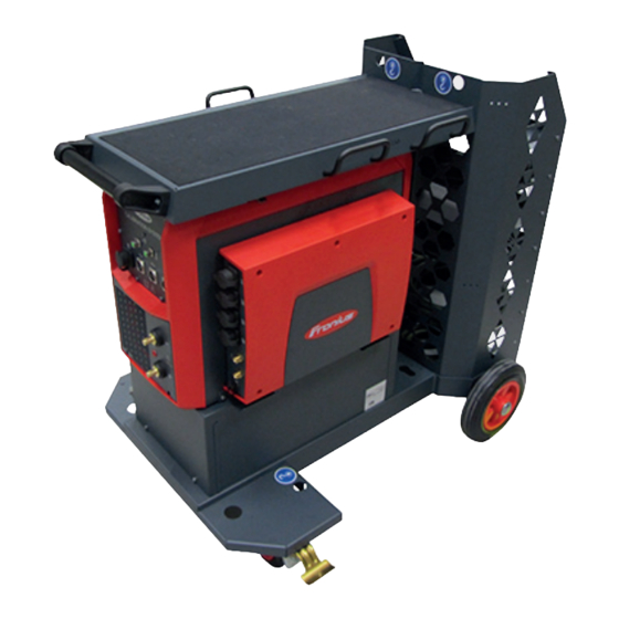
Page 25: Mechanical Components On Trolley
Mechanical components on trolley Calibration sys- Item Designation tem trolley Calibration system trolley (option) Accessory drawers Cable hanger Tray Storage trays... -
Page 27: Installation
Installation... -
Page 29: Installing The Calibration System
NOTE! If a version of TwinCat is already present on your PC (TwinCat 2 or TwinCat 3), in- stallation is not mandatory. However, Fronius recommends that the version of TwinCat provided is used. Open the path: \WT_SW_Fronius_CalibrationSystem2.0_vX.X.XX.X_MULTI\twincat Install the file located there and follow the setup instructions... -
Page 30: Tps/I Smartcard Driver
Depending on the operating system, select the subfolder (win / win_64) and follow the instructions After successful installation, the driver can be found under the network adapters: If a driver is already installed, ensure that it is the latest version and if necessary update it Also use the connected USB port for future work with the calibration system. - Page 31 If under Properties / General / Storage location NO port is specified for a SmartCard reader, it must be deactivated: Right-click on the affected SmartCard reader and select "Disable Device"...
-
Page 32: Localnet Ftdi Driver
LocalNet FTDI Connect the power source with LocalNet to the calibration system via USB and switch driver on both components Open the Device Manager If no driver is yet installed, the device will appear as unknown (USB Serial Port, USB- RS232 cable, etc.) Install the required driver software from the unzipped software package: Right click on USB Serial Port... -
Page 33: Changing Network Settings
Changing net- Setting network settings work settings via the calibration software: under the network settings (TCP/IPv4) of the adapter: Changing the net- IMPORTANT! Prerequisites for USB calibration: work settings for DHCP server, which starts automatically when the program starts. USB calibration .net Framework, at least version 4.7.2 Specify network settings for USB calibration Via the calibration software:... -
Page 34: Setting A Twincat Route
Setting a TwinCat Click on the TwinCat symbol in the lower bar of your PC and select "Edit routes" route Add a new route by going to "Add" and then "Broadcast Search" The calibration system is then normally displayed. Implement the following settings: Deactivate "Encrypt password (Twincat 3 only)"... - Page 35 Close the window by clicking "Close" Possible errors/points to check if the route cannot be set as described above include: Check network settings: the calibration station must be pingable at the address 192.168.120.50 Various security programmes (e.g. F-Secure, etc.) may block the network connection. If necessary, allow network traffic Reset the calibration station and ensure that the green LED is on Remove the USB cable for a short time, then reconnect it and try again...
-
Page 36: Setting The Language, System Information
Setting the language, system information Setting the lan- After the calibration software has been installed, the language can be set for the user guage interface: The system switches to the chosen language when the program is restarted. NOTE! Only the user interface of the calibration software is displayed in the chosen lan- guage. -
Page 37: Calibrating Welding Systems
Calibrating welding systems... -
Page 39: General Information
General information Mains voltage With single-phase machines, the mains voltage must be measured manually using a measurement for FLUKE measuring device. single-phase power sources Enter the measured mains voltage in the box [ ] Enable In Use Under external measuring equipment, enter the FLUKE measuring device used Correcting set If the values specified by the calibration software are not achieved, the set value or load values and load... -
Page 40: Calibrating Welding Systems With Localnet (Tps, Tst, Mw, Tt)
Calibrating welding systems with LocalNet (TPS, TSt, MW, TT) Overview - Local- Welding systems with external wirefeeder TS 4000 / 5000 TPS 3200 / 4000 / 5000 TIME 5000 Digital CMT 4000 Advanced TSt 3500/5000 TSt 3500 / 5000 Rob TSt 3500 / 5000 Syn Welding systems with integrated wire drive TPS 2700... - Page 41 Connect the + power cable to the cali- bration system and the power source Connect the sense lead (red) to the ca- libration system Connect the - power cable to the cali- bration system and the power source Connect the sense lead (blue) to the calibration system Connect the LocalNet/USB converter to the calibration system and to a free...
- Page 42 For TransSteel TSt 2200c only: A cable harness (item number 43,0004,4850) is also required when calibrating a TSt 2200c power source. The calibration process is performed with an open power source housing. WARNING! An electric shock can be fatal. All work on the power source may only be carried out in a de-energised state. Before opening the device ►...
-
Page 43: Connecting The Welding Wire Calibration System
Connecting the Connect the connection cable to the welding wire cali- welding wire calibration system bration system IMPORTANT! A maximum of 3 connection cables (max. 15 m) can be used to connect the welding wire cali- bration system and the calibration sys- tem! Connect the connection cable to the calibration system... -
Page 44: Connecting The Computer To The Calibration System And Signature Pad
NOTE! When calibrating robot welding systems, the welding wire calibration system is usu- ally attached to the contact tip of the robot welding torch. If, in this case, it is not possible to attach it properly, the following longer contact tips may be used on the robot welding torch: 42,0001,0056 contact tip 1.6/M6/ø8x33 mm... -
Page 45: Preparing The Gas Calibration System
Preparing the gas IMPORTANT! If a shielding gas supply is to be calibrated, it must be connected to the cali- calibration sys- bration system before starting the calibration process. The welding system and calibration system must be connected to each other. Connect the gas hose to the pressure regulator and to the Gas IN connection on the calibration system... -
Page 46: Calibrating The Welding System
Calibrating the IMPORTANT! Before starting the calibration process: welding system All devices to be calibrated must be connected to the calibration system: power source, wirefeeder, shielding gas supply; etc. In accordance with standard EN50504, the power source to be calibrated must be switched on at least 5 minutes before the calibration process starts. - Page 47 Click on [Establish connection] If the connection is established successfully, a message to this effect is displayed and the data from the power source and wirefeeder is automatically read in. Welding current, welding voltage and wire speed are pre-selected. To deselect them, click on the respective check box.
- Page 48 CAUTION! Risk of injury from emerging welding wire. As soon as the calibration process resumes, the welding wirefeed starts and the welding wire emerges. ► Keep the welding wire calibration system away from the head and body and wear suit- able protective goggles.
-
Page 49: Calibrating Welding Systems With Speednet (Tpsi)
Calibrating welding systems with SpeedNet (TPSi) Overview - Welding systems with external wirefeeder SpeedNet TPS 320i / 400i / 500i / 600i TPS 400i LSC ADV Welding systems with integrated wire drive TPS 270i C TPS 320i C The power sources listed above have a SpeedNet port and are calibrated using the follow- ing calibration process. -
Page 50: Connecting The Computer To The Calibration System And Signature Pad
Connecting the Connect the USB connection cable to the calibration system and the computer / laptop computer to the Connect the Signotec signature pad to the calibration system calibration sys- Switch on the power source tem and signature Preparing the gas IMPORTANT! If a shielding gas supply is to be calibrated, it must be connected to the cali- calibration sys- bration system before starting the calibration process. -
Page 51: Calibrating The Welding System
Connect the gas and data connections to each other Calibrating the IMPORTANT! Before starting the calibration process: welding system All devices to be calibrated must be connected to the calibration system: power source, wirefeeder, shielding gas supply; etc. In accordance with standard EN50504, the power source to be calibrated must be switched on at least 5 minutes before the calibration process starts. - Page 52 Enter the details for a new client: Name Address Post code Customer number Click on [Add] select current client from the list shown Under Others, inventory numbers, order numbers and observations can be entered. Click [Next >] The preliminary settings / device selection are displayed. Under Settings, select the connection to the power source: o SpeedNet Click on [Establish connection]...
- Page 53 Click [Next >] The summary of the calibration process is displayed. Define the calibration class: o Precision o Standard Click [Start automatic calibration process] The calibration process starts. When a calibration process is active A corresponding notification is displayed The [Interrupt calibration] button is available All measuring points are checked one after the other Current measured values are displayed A progress bar with the remaining time is displayed...
- Page 54 Press [OK] on the Signotec signature pad The signature is sent to the calibration software. x ... Cancel signature Refresh ... new signature A corresponding notification is displayed after the signature has been received suc- cessfully. Click [Create PDF] IMPORTANT! Only after the confirmation "PDF created successfully!" is displayed, will the calibration report be saved.
-
Page 55: Calibrating Welding Systems With Usb / Speednet
Calibrating welding systems with USB / SpeedNet Overview - USB Software version 1.0.28 and higher: TIG welding systems TransTig 230i MagicWave 190 MagicWave 230i Welding systems with external wirefeeder TPS 320i / 400i / 500i / 600i TPS 400i LSC ADV Welding systems with integrated wire drive TPS 270i C TPS 320i C... -
Page 56: Connecting The Welding Wire Calibration System
Connecting the Connect the connection cable to the welding wire calibration system welding wire cali- bration system IMPORTANT! A maximum of 3 connection cables (max. 15 m) can be used to connect the welding wire calibration system and the calibration system! Connect the connection cable to the calibration system Connect the welding torch to the welding system Remove the gas nozzle from the welding torch... -
Page 57: Calibrating The Welding System
Connect the gas hose to the wirefee- der or the power source and to the Gas OUT connection on the calibration sys- Connect the gas and data connections to each other Calibrating the IMPORTANT! Before starting the calibration process: welding system All devices to be calibrated must be connected to the calibration system: power source, wirefeeder, shielding gas supply;... - Page 58 Click on [Add] select current contractor from the list shown Enter the serial numbers of the measuring equipment: Calibration system Welding wire calibration system Gas measuring system Click [Next >] The preliminary settings / customer data are displayed. Enter the details for a new client: Name Address Post code...
- Page 59 Click [Next >] The preliminary settings / calibration parameters are displayed: five measured values M1 - M5 for each power source Welding current [A] Welding voltage [V] For the wirefeeder, enter five wire speed measured values M1 - M5 [m/min]: The measured value M5 is the maximum value for the wirefeeder.
- Page 60 CAUTION! Risk of injury from emerging welding wire. As soon as the calibration process resumes, the welding wirefeed starts and the welding wire emerges. ► Keep the welding wire calibration system away from the head and body and wear suit- able protective goggles.
-
Page 61: Calibrating Other Fronius Welding Systems
TransPocket 1100 / 1200 / 1400 / 1500 / 2000 TransPocket 2500 / 3500 - RC, TIG, Comfort AccuPocket 150 The Fronius power sources listed above do not have a SpeedNet or LocalNet port and are calibrated using the following calibration process. Connecting the... -
Page 62: Connecting The Welding Wire Calibration System
Connecting the Connect the connection cable to the welding wire calibration system welding wire cali- bration system IMPORTANT! A maximum of 3 connection cables (max. 15 m) can be used to connect the welding wire calibration system and the calibration system! Connect the connection cable to the calibration system Connect the welding torch to the welding system Remove the gas nozzle from the welding torch... - Page 63 Under Others, inventory numbers, order numbers and observations can be entered. Click [Next >] The preliminary settings / device selection are displayed. Under Settings, select: o Fronius devices Select the respective TransPocket variant Enter the serial number and name of the power source Click [Next >]...
- Page 64 Click [Next >] The preliminary settings / general measurement data are displayed. Click [Start measuring process] The following data is displayed: Ambient temperature [° C] Mains voltage [V] Open circuit voltage U IMPORTANT! The mains voltage displayed is incorrect! With single-phase machines, the mains voltage must be measured manually using a FLUKE measuring device, and entered! Measure the mains voltage Enter the mains voltage measured...
- Page 65 Enter the details to create the calibration report: Under Template, select the language for the calibration report from the list Enter the output path Enter or search for ( [Browse] ) the file name If the Signotec signature pad is connected and has been detected by the calibration system, a notification to this effect is displayed under Signature pad.
-
Page 66: Calibrating Transtig 1750 Puls
Calibrating Tran- IMPORTANT! Before starting the calibration process: sTig 1750 Puls All devices to be calibrated must be connected to the calibration system: power source, shielding gas supply, etc. In accordance with standard EN50504, the power source to be calibrated must be switched on at least 5 minutes before the calibration process starts. - Page 67 Under Others, inventory numbers, order numbers and observations can be entered. Click [Next >] The preliminary settings / device selection are displayed. Under Settings, select: o Fronius devices Select TransTig 1750 Puls Click [External start with calibration system] Enter the serial number of the TT 1750 Puls in the box Click [Next >]...
- Page 68 Click [Next >] The summary of the calibration process is displayed. Define the calibration class: o Precision o Standard Set the specified measured value M1 on the power source Click [ Start measuring process ] Enter the value displayed on the power source in the Display [A] box Click [Next >] Repeat steps 25 - 28 for the measured values M2 - M5 - M1 (10 measurements)
-
Page 69: Calibrating Variosynergic 3400
Calibrating Vario- IMPORTANT! Before starting the calibration process: Synergic 3400 The power source to be calibrated must be connected to the calibration system (if pos- sible, connect the relevant adapters). In accordance with standard EN50504, the power source to be calibrated must be switched on at least 5 minutes before the calibration process starts. - Page 70 Click [Next >] The preliminary settings / device selection are displayed. Under Settings, select: o Fronius devices Select VarioSynergic 3400 [Display available] and [External start with calibration system] have been pre-selected Enter the serial number of the VarioSynergic in the box Welding current, welding voltage and wire speed have been pre-selected.
- Page 71 Set the toggle switch to A (current) Set the selector switch on the interior of the device to 2-step mode. Click [Start measuring process] Carry out a visual inspection of the welding system and the calibration system, accord- ing to the calibration instructions If the visual inspection does not reveal any defects, select [Click here] Click [Next >] The summary of the calibration process is displayed.
- Page 72 At the end of the current and voltage calibration, the message [Start calibration feed system 1!] is displayed To calibrate the welding wire on the power source, specify the following settings: Set the toggle switch to wirefeeder. Depending on the measurement, set the wire speed Set the wirefeeder controller on the interior of the de- controller to the relevant measured value according to vice under MANUAL to 100 %.
- Page 73 Enter the value displayed on the power source under "Display" and click on [Next >] Repeat steps 43 - 45 for the measurements of M2 to M5 and M1 When the calibration process is complete, a notification is displayed to this effect and the [Print calibration report] button is available.
-
Page 75: Troubleshooting
Troubleshooting... -
Page 77: Troubleshooting
Troubleshooting The status indica- No power supply tor is not lit up Cause: Mains cable not connected Remedy: Connect the mains cable Cause: Faulty mains cable Remedy: Check the mains cable and replace if necessary Cause: Fuses F1 / F4 / F5 have tripped Remedy: Switch off the device, disconnect it from the mains, and check fuses, e.g.: using a multimeter... -
Page 79: Technical Data
Technical data... -
Page 81: Technical Data
Technical data Calibration sys- Mains voltage 100 - 240 V AC tem 2.0 Mains voltage tolerance +15 / -10 % Mains frequency 50/60 Hz Mains fuse protection (slow-blow) Primary current 3 A @ 100 V AC 1.5 A @ 240 V AC cos phi power factor 0.99 Internal power supply... -
Page 82: Interface Box
Interface box Operating voltage 24 V DC Degree of protection IP 20 EMC device class EN 61010 -1:2010 Safety symbols Dimensions l x w x h 466 x 355 x 85 mm Weight (incl. gas measurement I-kit) 3.85 kg Ambient temperature 0 –... - Page 84 FRONIUS INTERNATIONAL GMBH Vorchdorfer Straße 40, A-4643 Pettenbach, Austria E-Mail: sales@fronius.com www.fronius.com Under www.fronius.com/contact you will find the addresses of all Fronius Sales & Service Partners and locations...
Need help?
Do you have a question about the Calibration system 2.0 and is the answer not in the manual?
Questions and answers