
Related Manuals for MYTORQ MY-TR

Summary of Contents for MYTORQ MY-TR
- Page 1 Torque Display User Manual Model : MY-TR (Ver 2.00) SAING EI CORP. https://www.mytorqtools.com Y2F167-3E-019 20211201-V2129...
-
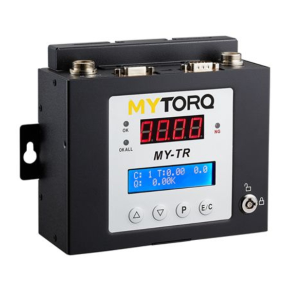
Page 2: Panel Function
1. Panel Function Display screen: 1. Four-digit seven-segment display of torque value 2. 16X2 LCM display setting function C: Display count value T: Display screwdriver action time 999.9 display number of turns Q: Display torque value S: Display status (OK, NGT, NGQ, NGC, OKALL..) ... - Page 3 Screwdriver port Power port (4PIN) RS232/PORT1 RS232/PORT2 (6PIN) Anti-interference Connect Barcode small torque MYP32-300N Connect DAS cable Scanner MYP40-1500 Anti-interference Connect Barcode power torque Connect DAS cable Scanner MYP40-500 (MY8 series) Remark: Please switch the power controller HI/LO switch to "HI" position. 2.
- Page 4 Tool product serial serial number Before the tool exit the factory (electric screwdriver), the factory number provides the tool a serial number. When equipment (MY-TR) needs to be replaced, the tool serial number can be searched from the equipment end.
- Page 5 Set Up Time and Factory Setting Name Function Interpretation Value Value ALIGNMENT XXXX/00/00 00:00 Record calibration date and time. XXXX/00/00 TIME 00:00 TORQUE 0-250、 Torque Filter Function : FILTER : Disable Filter UMLIMITED 1 - 250: Enable Filter Counter UMLIMITED:Infinite filtering [3]DEVICE ID 1-255 Equipment No.
-
Page 6: Load Default
Set Up Time and Factory Setting Name Function Interpretation Value Value [4]PASSWORD A0000 Set up password lock. A0000 CONTROL VER. V2.XXX Mainboard version. V2.XXX SCREWDRIVER V2.XX Screwdriver version. V2.XX VER. Action Limitation RR/RS AUTO FORWARD (RR/RS) AUTO REV. TIME (RT) AUTO STOP TIME (PT) RECONFIRM TIME (LL) Remarks: V - setting available, X - OFF... - Page 7 2. When installing an automated machine, it is recommended to first install the signal cable at the machine end and then connect it to the MY-TR. When collaborating with automated controls, please notes to the above items to prevent equipment damage.
-
Page 8: Confirm Mode
6. CONFIRM Mode Code Description Remarks Refers to a switch SENSOR confirmation method External sensor switch Refers to two switch SENSORS In case of errors, SENSOR needs to be in detection, and the panel displays External sensor switch “Er”; the “CONIRM” on the panel needs to be pressed again or the external confirmation (CN7+CN8 close circuit) in order to clear the “Er”... -
Page 9: Data Frame
9. BARCODE instructions: 9-1. Hardware description Connect Bar code Reader to port 1 on MY-TR through RS232 9-2. Barcode Reader Set function options <Serial interface> Record Suffix ===>CR Baud Rate ===>9600 BPS <Data Frame> Data Bits ===>8 Parity ===>None Stop Bits... - Page 10 Use MYTORQ barcode for Program switching, 1-99 groups can be switched (CMD.P01-CMD.P99) Instructions: 99 sets of programs have been preset on the MY-TR. The barcode of the group to be used must be pasted on the workpiece in advance. (eg: CMD.P01~CMD.P99) When the workpiece comes in for fastening purpose, you need to scan the workpiece or pre- prepared barcode before the tool can be used and switch to the correct group.
- Page 11 : CMD.C02 release NS (Nok Stop) Description: The NS function has been enabled on the MY-TR. When an NS occurs, the screwdriver locks out and cannot be used. The operator can use Barcode Reader to scan the prepared command bar code to release it for easy operation.
-
Page 12: Grounding Instructions
Do not use the electric screwdriver driver for other machines. 4、If the MY-TR overheats occurred or the load current exceeds the maximum rated current of the fuse, the quick type fuse will blow automatically cut off the power supply; please immediately stop operation as abnormal condition occurred such as continue fasten shut-off or the switching power, and the MY-TR and electric screwdriver is required return for repair service. - Page 13 MY-TR V2.0/MY-TR5 Data transmission description and flow control suggestion VER:2020060201 1. Controller power on and time synchronization After controller is power on, it will send data {REQ0...} each second to inform external device such as computer、PLC、AMS. It needs to reply {CMD0,..} that controller function normally and controller time.
- Page 14 Controller write to external device REQ0(send/sec.) Controller respond time CMD0(send/sec.) Controller External device Barcode input to controller REQ1 MY-TR/MY-TR5 PC/AMS/PLC Controller feedback time (Master) (Slave) CMD0 Data write in to controller DATA0(check column 6 if it’s new data) Controller feedback time...
- Page 15 Serial communication Mode -ASCII (American Standard Code for Information Interchange) There are three basic data output formats send from device (MY-TR/MY-TR5) to external system (DAS/AMS/Other System) via the buildin RS232 port on the device : 1.Command {REQ0} : Send from Device to Host (Send device status to host per second after device startup ready) 2.Command {REQ1} : Send from Device to Host (Send barcode data to host immediately after barcode scaned a data)
- Page 16 Current value 20 Current value 00000-65535 String 5 Byte 146-150 This field is only available for MY-TR 2.124 and MY-TR5 2.006. 21 Year 0001~9999 String 4 Byte 152-155 Year 22 Month 01~12 String 2 Byte 157-158 Month 23 Date 01~31...
- Page 17 Power Controller MODEL: MY-TR-V2.0 CUSTOMER DWG NAME PRODUCTION NO. ITEM NO: DWG NO: MATERIAL SHRINK TITLE: DES. BY DATE THIRD ANGLE PROJECTION. CHKD.BY DATE UNIT SCALE SHT NO. APPD.BY DATE OF SHTS.
- Page 18 MY-TR-V2.0 No. PARTS NO. PARTS NAME-E PARTS NAME-C Q'ty 1 AA50001-139N CORD ASSEMBLY (BC6Pin) 3M 連接線 BC6PIN 3M隔離線灰色 2 AA50005-B6P-7-2 CORD ASSEMBLY (BC6Pin&4Pin) 2M連接線 BC6P轉4P 2M 3 P11404-6 Key (1506) 鑰匙 (1506) 4 P11404-8 Key Switch ASS'Y 鑰匙開關半成品 5 YTM0173-1 Sticker-Model 面板貼紙...
Need help?
Do you have a question about the MY-TR and is the answer not in the manual?
Questions and answers