Table of Contents
Advertisement
Quick Links
MIKI PULLEY/TRS-CBUN-E-001H-00/MD-000103254
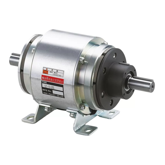
ELECTROMAGNETIC CLUTCH & BRAKE
ELECTROMAGNETIC CLUTCH AND BRAKE UNITS
121/122/125/126
Instruction Manual
☆This instruction manual describes mainly installation, removal, and notes pertaining to same for
standard-specification products after purchase; see the Miki Pulley website and our latest catalog for product
specifications and performance.
☆Before use this product, read the instruction manual carefully and use the product safely and correctly.
☆First, please check that it is the correct product and if the product was damaged during transportation.
CONTENTS
1.STRUCTURE AND PARTS
2.NOTES
3.MOUNTING
1.STRUCTURE AND PARTS
Note The device (application) and structure depend on the product model and type.
Note The base can be either steel plate or cast, depending on the product model and size.
[1]Housing [2]Rotor [3]Clutch armature [4]Clutch stator
[5]Brake armature [6]Brake stator [7]Base [8]Terminal block
※Description of model names is given for Model 125
■125
4.CONNECTION
5.OPERATION CHECK
6.MAINTENANCE & INSPECTION
1
-
-
121/122/125/126
Advertisement
Table of Contents

Summary of Contents for Miki Pulley 121 Series
- Page 1 Instruction Manual ☆This instruction manual describes mainly installation, removal, and notes pertaining to same for standard-specification products after purchase; see the Miki Pulley website and our latest catalog for product specifications and performance. ☆Before use this product, read the instruction manual carefully and use the product safely and correctly.
- Page 2 MIKI PULLEY/TRS-CBUN-E-001H-00/MD-000103254 121/122/125/126 2.NOTES 2.1 SAFETY PRECAUTIONS Please read carefully through the instruction manual and the technical information for proper use and safety. In this manual, safety precautions are classified by "DANGER" and "CAUTION". 【CLASS】 DANGER When death or serious injury may result by mishandling.
- Page 3 MIKI PULLEY/TRS-CBUN-E-001H-00/MD-000103254 121/122/125/126 2.2 IMPORTANT POINTS OF PRODUCT SPECIFICATIONS Do not use the product in a bad Request disposal with a environment. waste-collection company, or dispose Product is for dry use; do not allow of according to laws and regulations.
- Page 4 MIKI PULLEY/TRS-CBUN-E-001H-00/MD-000103254 121/122/125/126 3.MOUNTING (1) Securely fasten base on sturdy and flat surface with bolts and washers. Installation in any direction is possible. See chart for dimensions of holes for installing base. Select the bolt length according to your design specifications.
- Page 5 MIKI PULLEY/TRS-CBUN-E-001H-00/MD-000103254 121/122/125/126 【Dimensions for screw holes at end of shaft and on end face of armature hub】 ※Screw holes at end of shaft not provided with 125-05-12G. (3) Install the CB unit to the machine so that the travel lines are correct, and to align the centers of both shafts correctly.
- Page 6 MIKI PULLEY/TRS-CBUN-E-001H-00/MD-000103254 121/122/125/126 【OVERHANG LOAD OF UNIT】 ※Numbers in parentheses are for loads in the same direction. ※126-□-4B:Mounting type (Base-mounted) 4.CONNECTION Beforehand, be sure to see “Items Checked for Design Purposes”, etc. in the catalog, and also again check aspects which were considered when designing the system such as circuits (control circuit, power supply circuit, discharge circuit) and components for power supplies (transformers, rectifiers, relays).
- Page 7 MIKI PULLEY/TRS-CBUN-E-001H-00/MD-000103254 121/122/125/126 4.4 TERMINAL BLOCK AND COVER/LEAD WIRE ■TERMINAL BLOCK The terminal block is set on the housing or drum, or on the base depending on the model and size. ※The shape of the terminal set on the base and the cover may differ from the figure.
- Page 8 Any increase more than the threshold results in a degrade in performance, and requires adjustment of the air gap. Before adjusting the air gap, contacting Miki Pulley to confirm is recommended. Contact by email Please contact us using the inquiry form and be aware that support for inquiries received on Saturdays, Sundays, holidays, New Year's, and summer business holidays will be provided on the next business day.


Need help?
Do you have a question about the 121 Series and is the answer not in the manual?
Questions and answers