
Related Manuals for DP Pumps Hydro-Unit Premium


Summary of Contents for DP Pumps Hydro-Unit Premium
- Page 1 Pressure Booster System Installation/Operating Manual Hydro‑Unit Premium Line Hydro-Unit Premium Line F Hydro-Unit Premium Line VC Hydro-Unit Premium Line SVP...
- Page 2 2 / 96 Legal information/Copyright Original operating manual Hydro‑Unit Premium Line All rights reserved. The contents provided herein must neither be distributed, copied, reproduced, edited or processed for any other purpose, nor otherwise transmitted, published or made available to a third party without the manufacturer's express written consent.
-
Page 3: Table Of Contents
Contents Glossary...................... 6 General....................... 7 Principles ............................. 7 Software changes .......................... 7 Installation of partly completed machinery................... 7 Target group ............................ 7 Other applicable documents ........................ 7 Symbols ............................... 7 Key to safety symbols/markings ...................... 8 Safety ......................... 9 General .............................. 9 Intended use ............................ 9 2.2.1 Prevention of foreseeable misuse ................... - Page 4 Connecting the piping ........................ 28 5.4.1 Fitting an expansion joint (optional).................. 29 5.4.2 Fitting the pressure reducer (optional) .................. 29 Electrical connection .......................... 30 5.5.1 Sizing the power cable ...................... 30 5.5.2 Connecting the pressure booster system................ 31 5.5.3 Connecting the remote ON/OFF input................... 31 5.5.4 Connecting the dry running protection device ...............
- Page 5 Related Documents .................. 57 10.1 General assembly drawings/exploded views with list of components .......... 57 10.1.1 Hydro-Unit Premium Line F.................... 57 10.1.2 Hydro-Unit Premium Line VC .................... 58 10.1.3 Hydro-Unit Premium Line SVP.................... 59 10.2 Parameter lists ........................... 60 10.2.1 Configuration ......................... 60 10.2.2 Settings ..........................
-
Page 6: Glossary
Glossary Accumulator Pressure losses may occur in the piping downstream of the pressure booster system as a result of losses due to leakage. The accumulator serves to compensate for pressure losses and minimises the frequency of starts of the pressure booster system. -
Page 7: General
1 General 1.1 Principles This operating manual is valid for the type series and variants indicated on the front cover. The operating manual describes the proper and safe use of this equipment in all phases of operation. The name plate indicates the type series, the main operating data and the serial number. The serial number uniquely describes the product and is used as identification in all further business processes. -
Page 8: Key To Safety Symbols/Markings
1.7 Key to safety symbols/markings Table 3: Definition of safety symbols/markings Symbol Description DANGER DANGER This signal word indicates a high-risk hazard which, if not avoided, will result in death or serious injury. WARNING WARNING This signal word indicates a medium-risk hazard which, if not avoided, could result in death or serious injury. -
Page 9: Safety
2 Safety All the information contained in this section refers to hazardous situations. DANGER In addition to the present general safety information the action-related safety information given in the other sections must be observed. 2.1 General – This operating manual contains general installation, operating and maintenance instructions that must be observed to ensure safe operation of the system and prevent personal injury and damage to property. -
Page 10: Personnel Qualification And Personnel Training
2.3 Personnel qualification and personnel training – All personnel involved must be fully qualified to install, operate, maintain and inspect the product this manual refers to. – The responsibilities, competence and supervision of all personnel involved in transport, installation, operation, maintenance and inspection must be clearly defined by the operator. -
Page 11: Safety Information For Maintenance, Inspection And Installation
2.7 Safety information for maintenance, inspection and installation – Modifications or alterations of the pressure booster system are only permitted with the manufacturer's prior consent. – Use only original spare parts or parts authorised by the manufacturer. The use of other parts can invalidate any liability of the manufacturer for resulting damage. -
Page 12: Line Harmonics Requirements
Table 4: Categories of intended use Category Definition Limits to EN 55011 Frequency inverters with a supply voltage under 1000 V installed in the first Class B environment (residential and office areas). Frequency inverters with a supply voltage under 1000 V installed in the first Class A, Group 1 environment (residential and office areas) that are neither ready to be plugged in/ connected nor are mobile and must be installed and commissioned by specialist... - Page 13 The following relevant generic standards are used for the interference immunity test: – EN 61000-4-2: Electromagnetic compatibility (EMC) – Part 4-2: Testing and measurement techniques – Electrostatic discharge immunity test – EN 61000-4-3: Electromagnetic compatibility (EMC) – Part 4-3: Testing and measurement techniques – Radiated, radio-frequency, electromagnetic field immunity test –...
-
Page 14: Transport/Storage/Disposal
3 Transport/Storage/Disposal 3.1 Checking the condition upon delivery 1. On transfer of goods, check each packaging unit for damage. 2. In the event of in-transit damage, assess the exact damage, document it and notify DP or the supplying dealer and the insurer about the damage in writing immediately. 3.2 Transport DANGER Pressure booster system tipping over... -
Page 15: Return To Supplier
2. Separate and sort the pump materials, e.g. by: - Metals - Plastics 15 / 96 - Electronic waste - Greases and other lubricants 3. Dispose of materials in accordance with local regulations or in another controlled manner. Hydro-Unit Premium Line VC: +30 °C... - Page 16 Electrical or electronic equipment marked with the adjacent symbol must not be disposed of in household waste at the end of its service life. Contact your local waste disposal partner for returns. If the used electrical or electronic equipment contains personal data, the operator is responsible for deleting it before the equipment is returned.
-
Page 17: Description
For information as per chemicals Regulation (EC) No. 1907/2006 (REACH), see http:// www.dp.nl/reach. 4.3 Designation Example: HU3 Premium Line DPV 15/7 C SVP Table 8: Designation key Code Description Hydro-Unit Premium Type series Line Number of pumps DPV 15 Size Number of stages Design... - Page 18 Inlet conditions Enclosure Serial number Order number Month of production / year of production, consecutive number 18 / 96 M = Inlet side of pressure booster system connected to the municipal water supply, suction head operation, F = Pressure booster system with break tank arranged on same level as pump, suction head operation, L = Pressure booster system with break tank arranged at a lower level, suction lift operation...
-
Page 19: Design Details
– Hydraulic components made of stainless steel / brass – Integrated dry running protection Hydro-Unit Premium Line F: – DOL starting Hydro-Unit Premium Line VC, SVP: – With variable speed system Multiple pump system: – Discharge-side gate valve per pump For inlet conditions M and F only: –... -
Page 20: Configuration And Function
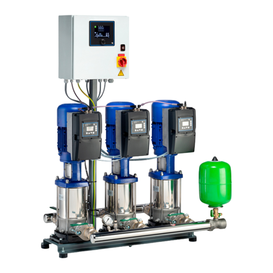
4.6 Configuration and function Fig. 2: Configuration Hydro-Unit Premium Line VC / SVP Control box Membrane-type accumulator Control unit Manifold Pump Baseplate Description Fully automatic pressure booster system with two, three or four vertical high-pressure pumps (3) for ensuring the required supply pressure. -
Page 21: Noise Characteristics
If the demand drops towards 0, the pressure booster system slowly runs down to the stop point. Hydro-Unit Premium Line SVP: 1 volt-free general contact is provided in the control cabinet for reporting warnings and alerts, respectively. -
Page 22: Inlet Conditions, Version M
– One frequency inverter per pump 4.8.1 Inlet conditions, version M Fig. 3: M = Inlet side of pressure booster system connected to the municipal water supply, suction head operation 22 / 96 Fig. 4: Scope of supply for version M Suction line (included in DP’s scope of supply) Lift check valve (included in DP’s scope of supply) Dry running protection (included in DP’s scope of supply) -
Page 23: Inlet Conditions, Version F
4.8.2 Inlet conditions, version F Fig. 5: F = Pressure booster system with break tank arranged on same level as pump, suction head operation Fig. 6: Scope of supply, version F 23 / 96 Suction line (included in DP’s scope of supply) Lift check valve (included in DP’s scope of supply) Dry running protection (not included in DP’s scope of supply) -
Page 24: Inlet Conditions, Version L
4.8.3 Inlet conditions, version L Fig. 7: L = Pressure booster system with break tank arranged at a lower level, suction lift operation 24 / 96... -
Page 25: Dimensions And Weights
Fig. 8: Scope of supply, version L Suction line (included in DP’s scope of supply) Lift check valve (included in DP’s scope of supply) Dry running protection (not included in DP’s scope of supply) Foot valve (not included in DP’s scope of supply) 25 / 96 4.9 Dimensions and weights For dimensions and weights refer to the outline drawing. - Page 26 Fig. 9: PE connection Earthing terminal Location of power connection 26 / 96...
-
Page 27: Installation At Site
WARNING Top-heavy pressure booster system Risk of personal injury by pressure booster system tipping over! Ø Pressure booster systems awaiting final installation must be secured against tipping over. Ø Firmly anchor the pressure booster system. Hydro-Unit Premium Line VC: +30 °C... -
Page 28: Mounting The Accumulator
NOTE To prevent the transmission of piping forces and solid-borne noise, installing expansion joints with length-limiters is recommended. ü The pressure booster system’s packaging has been removed. ü A suitable installation site has been selected that meets the requirements. ü Sufficient clearance in all directions is provided for servicing work. 1. -
Page 29: Fitting An Expansion Joint (Optional)
5.4.1 Fitting an expansion joint (optional) DANGER Sparks and radiant heat Fire hazard! Ø Take suitable precautions to protect the expansion joint if any welding work is carried out. CAUTION Leaking expansion joint Flooding of installation room! Ø Never use the expansion joint to compensate for misalignment or mismatch of the piping. -
Page 30: Electrical Connection
5.5 Electrical connection DANGER Electrical connection work by unqualified personnel Danger of death from electric shock! Ø Always have the electrical connections installed by a trained and qualified electrician. Ø Observe regulations IEC 60364 . WARNING Incorrect connection to the mains Damage to the power supply network, short circuit! Ø... -
Page 31: Connecting The Pressure Booster System
5.5.2 Connecting the pressure booster system ü The pressure booster system can be operated on the power supply network in accordance with the data on the name plate. ü The wiring diagram is available. 1. Connect terminals L1, L2, L3, PE and N in accordance with the wiring plan. 2. -
Page 32: Commissioning/Start-Up/Shutdown
6 Commissioning/Start-up/Shutdown 6.1 Commissioning/Start-up 6.1.1 Prerequisites for commissioning/start-up CAUTION Pump set running dry Damage to the pump set/pressure booster system! Ø Use dry running protection. If the dry running protection terminal is disabled by means of a bridge, the operator shall assume responsibility for any dry running that might occur. -
Page 33: Dry Running Protection
ü The original operating manual of the pump set is on hand. ü The pipe unions between the pump set and the piping have been re-tightened. ü Flange connections have been firmly tightened. ü The cooling air inlet openings and cooling air outlet openings at the motor are unobstructed. -
Page 34: Commissioning/Start-Up Of Pressure Booster System
6.1.5 Commissioning/start-up of pressure booster system NOTE Prior to its delivery, the pressure booster system will be tested hydraulically with water and then drained again. For technical reasons the presence of some residual water is unavoidable. Prior to commissioning/start-up observe EN 806. After prolonged standstill periods, flushing or professional disinfection is recommended. -
Page 35: Checklist For Commissioning/Start-Up
NOTE Minor leakage of the mechanical seals during commissioning is normal and will cease after a short period of operation. 6.1.6 Checklist for commissioning/start-up Table 10: Checklist Actions Done Read the operating manual. Verify the power supply against the name plate data. Check the earthing system (taking measurements). -
Page 36: Operating Limits
6.2 Operating limits DANGER Non-compliance with operating limits Damage to the pump set! Ø Comply with the operating data indicated in the data sheet. Ø Avoid operation against a closed shut-off element. Ø Never operate the pump set outside the limits specified below. DANGER Non-compliance with operating limits for the fluid handled Explosion hazard! -
Page 37: Minimum Flow Rate
6.2.4.2 Fluid temperature Table 12: Temperature limits of the fluid handled Permissible fluid temperature Value Maximum +60 °C +25 °C to DIN 1988 (DVGW) Minimum 0 °C 6.2.5 Minimum flow rate Table 13: Minimum flow rate per pump in manual mode Size Minimum flow rate per pump [l/h] DPV 2 DPV 4... -
Page 38: Measures To Be Taken For Shutdown
6.3.2 Measures to be taken for shutdown Fig. 12: Venting and draining the accumulator Vent plug Vent valve lever ü The pressure booster system has been switched off. [ð Section 6.3.1, Page 37] 1. Turn the ball valve lever 2 by 45 degrees. 2. Open the vent plug 1 at the accumulator. ð... -
Page 39: Operation
7 Operation 7.1 Control panel Fig. 13: Control panel Screen [ð Section 7.1.1, Page 39] Turn/push button [ð Section 7.1.2, Page 39] Status LED [ð Section 7.1.3, Page 39] 7.1.1 Screen To save power the screen is turned off automatically. To turn on the screen push or turn the turn/push button arranged below the screen. If a message is active, the screen also lights up and displays the current message ID as well as the system status. -
Page 40: Symbols On The Screen
Table 14: Explanation of the status LED Colour of the status LED Description Green (flashing) System in operation, no messages are active. Green (continuous) One or more information messages are active. Yellow (continuous) One or more warning messages are active (as well as any messages of a lower priority). -
Page 41: Operating Status Of The System
7.2.1 Operating status of the system Table 15: Symbols for the operating status of the system Symbol Description Status OK No warning messages or alert messages are active. Information messages may be present. The system is running without any problems. Warning One or more warning messages are active (as well as any messages of a lower priority). -
Page 42: Locking/Unlocking The Screen
7.2.3 Locking/unlocking the screen Table 17: Symbols for locking/unlocking the screen Symbol Description Screen settings locked No settings can be made but information can still be displayed, e.g. pump load. Error messages are limited to the selected part. Screen settings unlocked Changes can be made on the screen. -
Page 43: Operating The Device Via The Control Panel
Table 19: Symbols for information on the system Position Refers to Description Display for suction-side Depending on the connected sensors the following values are displayed: sensors – Version with pressure gauge: Displays the pressure at the inlet of the pressure booster system. –... -
Page 44: Unlocking The Screen
7.3.1 Unlocking the screen When the screen is locked, no settings can be made. In this state, only information can be displayed. 1. Turn the turn/push button to select the Locking/unlocking the screen symbol. Then press the turn/push button. ð The symbol flashes. 2. -
Page 45: Activating The Bluetooth Connection
7.3.5 Activating the Bluetooth connection 1. Press the turn/push button for a minimum of 5 seconds. ð The Bluetooth connection symbol flashes. [ð Section 7.2.2, Page 41] While the Bluetooth connection symbol flashes, the control unit can be connected to a wireless device. An existing connection is displayed by a continuously lit Bluetooth connection symbol on the screen. -
Page 46: Servicing/Maintenance
8 Servicing/Maintenance 8.1 General information/safety regulations DANGER Unintentional start-up of pressure booster system Danger to life! Ø De-energise the pressure booster system for any repair work or servicing work. Ø Ensure that the pressure booster system cannot be re-energised unintentionally. WARNING Improper lifting/moving of heavy assemblies or components Personal injury and damage to property! -
Page 47: Servicing/Inspection
8.2 Servicing/Inspection 8.2.1 Supervision of operation CAUTION Increased wear due to dry running Damage to the pump set! Ø Never operate the pump set without liquid fill. Ø Never close the shut-off element in the suction line and/or supply line during pump operation. -
Page 48: Maintenance Schedule
Check the automatic switching functionality. Check the start and stop points of the pressure booster system. Check the water inflow, lack-of-water monitoring and pressure reducer. 8.2.3 Maintenance schedule Table 20: Overview of maintenance work Maintenance interval Servicing/maintenance work At least once a year Check the pump sets for smooth running and the mechanical seal for integrity. -
Page 49: Replacing The Non-Return Valve
4. Check the pre-charge pressure using suitable equipment (e.g. tyre pressure gauge). 5. Fit the protective cap of the membrane-type accumulator valve. Filling the membrane-type accumulator 1. Remove and store the protective cap of the membrane-type accumulator valve. 2. Add nitrogen through the valve. 3. - Page 50 Fig. 20: Removing the body 7. Remove the body of the non-return valve. 8. Remove the insert check valve including O-rings. 9. Remove excessive contamination or deposits with a clean cloth. 10.Re-insert the insert check valve into the body. Apply lubricant to new O-rings. See table below.
-
Page 51: Mounting The Manifold In A Mirrored Position
Fig. 23: Verifying the alignment 13.Verify the correct alignment. Fig. 24: Fitting the screw 14.Fit and tighten the screw. 15.Close the drain plugs of the pump. Properly dispose of the fluid collected. 16.Slowly open the shut-off valve and check for any leakage. Table 21: Spare parts for servicing non-return valves, per pump Material number Description... - Page 52 Fig. 25: Removing the bolts 5. Remove the tie bolts between the two oval flanges and the pumps. Fig. 26: Removing the manifold 6. Remove the entire manifold (with shut-off valves). 52 / 96 Fig. 27: Loosening the EF locknut EF locknut...
- Page 53 7. Undo the EF locknut at both shut-off valves by half a turn. The O-ring is now exposed. Fig. 28: Turning the pressure measuring set Pressure measuring set Lever of the shut-off valve 8. Close the lever of the shut-off valve about half way to enable the 180° turn required in the next step.
- Page 54 Fig. 29: Turning the shut-off valves Shut-off valve 10.Turn the shut-off valves by 180°. Then turn the manifold with shut-off valves by 180°. 54 / 96 Fig. 30: Turning the pressure measuring set Pressure measuring set 11.Turn the pressure measuring set by a last 90°. 12.If the pressure gauge and/or pressure sensors have been removed, connect them again.
-
Page 55: Trouble-Shooting
9 Trouble-shooting WARNING Improper work to remedy faults Risk of injury! Ø For any work performed to remedy faults, observe the relevant information given in this operating manual and/or in the product literature provided by the accessories manufacturer. NOTE Please contact DP Service before carrying out any work on the pump's internal parts during the warranty period. - Page 56 A B C D E F G H J K L Possible cause Remedy ✘ ✘ ✘ ✘ ✘ ✘ Pressure transmitter set incorrectly or Check setting. defective ✘ ✘ ✘ Pre-charge pressure of the accumulator Restore nitrogen cushion. too low ✘...
-
Page 57: Related Documents
10 Related Documents 10.1 General assembly drawings/exploded views with list of components 10.1.1 Hydro-Unit Premium Line F 79-1 79-2 743.90 742.02 742.01 743.90 Fig. 31: Hydro-Unit Premium Line F Table 23: List of components Part No. Description Part No. Description 79-1 Automatic control unit... -
Page 58: Hydro-Unit Premium Line Vc
10.1.2 Hydro-Unit Premium Line VC 79-1 79-2 743.90 742.02 742.01 743.90 Fig. 32: Hydro-Unit Premium Line VC Table 24: List of components Part No. Description Part No. Description 79-1 Automatic control unit Pressure gauge 79-2 Measuring transducer 742.01/.02 Lift check valve O-ring... -
Page 59: Hydro-Unit Premium Line Svp
10.1.3 Hydro-Unit Premium Line SVP 79-1 79-2 743.90 742.02 742.01 743.90 Fig. 33: Hydro-Unit Premium Line SVP Table 25: List of components Part No. Description Part No. Description 79-1 Automatic control unit Pressure gauge 79-2 Measuring transducer 742.01/.02 Lift check valve O-ring... -
Page 60: Parameter Lists
10.2 Parameter lists 10.2.1 Configuration 10.2.1.1 System settings Table 26: System settings parameters Parameter Description Value range and dependencies Factory setting Access level Read Access level Write Re-start required Configuration Everybody Nobody System Everybody Nobody 1-1-1 Information Everybody Nobody 1-1-1-1 Order number Full text (max. - Page 61 Parameter Description Value range and dependencies Factory setting Access level Read Access level Write Re-start required 1-1-3-2 Number of base load pumps 1 … (number of pumps - number of peak- Number of pumps Everybody Nobody load pumps) if pump groups = base-load and peak-load pump control 1 …...
- Page 62 10.2.1.2 Pump settings Table 27: Pump settings parameters Parameter Description Value range and dependencies Factory setting Access level Read Access level Write Re-start required Pumps Everybody Nobody 1-2-1 Base load pump Everybody Nobody 1-2-1-1 Pump data Everybody Nobody 1-2-1-1-5 Head 0 Pump data Everybody Service...
- Page 63 Parameter Description Value range and dependencies Factory setting Access level Read Access level Write Re-start required 1-2-1-1-32 NPSH 6 Pump data Everybody Service 1-2-1-1-33 Optimal flow rate Pump data Everybody Service 1-2-1-1-34 Low-flow limit rate percentage Pump data Everybody Service 1-2-1-2 Motor drive data Everybody Nobody...
- Page 64 Parameter Description Value range and dependencies Factory setting Access level Read Access level Write Re-start required 1-2-1-2-22 Function input 1 [1] Reset Motor data Everybody Service [10] Reversing 1-2-1-2-23 Function input 2 [0] No operation Motor data Everybody Service [1] Reset [2] Coast inverse 1-2-1-2-24 Function input 3...
- Page 65 Parameter Description Value range and dependencies Factory setting Access level Read Access level Write Re-start required 1-2-1-2-29 Control timeout function [4] Max. speed Motor data Everybody Service [5] Stop and trip 1-2-1-2-30 Coasting select [0] Digital input Motor data Everybody Service [1] Bus [2] Digital input and bus...
- Page 66 10.2.1.3 Input / outputs Table 28: Input/output parameters Parameter Description Value range and dependencies Factory setting Access level Read Access level Write Re-start required Inputs/outputs Everybody Nobody 1-3-1 Analog inputs Everybody Nobody Note: To change a function, the Everybody Nobody function first has to be removed by changing it to 'No function'.
- Page 67 Parameter Description Value range and dependencies Factory setting Access level Read Access level Write Re-start required 1-3-3-1 Input 1 None None Everybody Service 1-3-3-2 Input 2 Pressure switch 1-3-3-3 Input 3 Float switch 1-3-3-4 Input 4 Flow switch 1-3-3-5 Input 5 Failure motor-circuit breaker pump 1 1-3-3-6 Input 6...
- Page 68 Parameter Description Value range and dependencies Factory setting Access level Read Access level Write Re-start required 1-3-3-1 Input 1 Manual-mode at M-0-A-switch rainwater None Everybody Service pump 2 1-3-3-2 Input 2 Automatic-mode at M-0-A-switch rainwater 1-3-3-3 Input 3 pump 1 1-3-3-4 Input 4 Automatic-mode at M-0-A-switch rainwater...
- Page 69 Parameter Description Value range and dependencies Factory setting Access level Read Access level Write Re-start required 1-3-4-1 Output 1 No function None Everybody Service 1-3-4-2 Output 2 Start/stop pump 1 1-3-4-3 Output 3 Start/stop pump 2 1-3-4-5 Output 5 (extension board) Start/stop pump 3 1-3-4-6 Output 6 (extension board)
- Page 70 Parameter Description Value range and dependencies Factory setting Access level Read Access level Write Re-start required 1-3-5-3 Selection of thermometer function Ambient temperature Ambient temperature Everybody Service Water temperature 1-3-7 Calibration 1-3-7-1 Sensors 1-3-7-1-1 Pressure sensor on suction side 1-3-7-1-1-1 Value at 4 mA 0 …...
- Page 71 10.2.1.4 Further configuration settings Table 29: Further configuration settings parameters Parameter Description Value range and dependencies Factory setting Access level Read Access level Write Re-start required Field bus Everybody Nobody 1-4-1 Modbus RTU Disabled Disabled Everybody Service Enabled 1-4-2 Slave address 1 …...
-
Page 72: Settings
Parameter Description Value range and dependencies Factory setting Access level Read Access level Write Re-start required 1-7-1-3 Seconds 0 … 59 Everybody Service 1-7-2 Date Everybody Nobody 1-7-2-1 Year 2019 … 2099 Everybody Service 1-7-2-2 Month 1 … 12 Everybody Service 1-7-2-3 1 …... - Page 73 Parameter Description Value range and dependencies Factory setting Access level Read Access level Write Re-start required 2-1-3 Alternative setpoint 0 … 99 bar 2.5 bar Everybody Customer 2-1-4 Alternative setpoint selection Disabled Disabled Everybody Customer Time enabled Digital input enabled 2-1-5 Alternative set-point start time 0 … 24 h Everybody...
- Page 74 Parameter Description Value range and dependencies Factory setting Access level Read Access level Write Re-start required 2-2-1-4 Pump 4 Manual-On Manual-Off Everybody Display/Customer 2-2-1-5 Pump 5 Automatic Manual-Off Everybody Display/Customer Manual-Off Manual-On 2-2-1-6 Pump 6 Automatic Manual-Off Everybody Display/Customer Manual-Off Manual-On 2-2-2 Rainwater operating mode...
- Page 75 10.2.2.4 Pump protection Table 33: Pump protection parameters Parameter Description Value range and dependencies Factory setting Access level Read Access level Write Re-start required Pump protection Everybody Nobody 2-4-1 General 2-4-1-1 Minimum frequency 0 … maximum frequency 60 Hz Everybody Service 2-4-1-2 Maximum frequency Minimum frequency …...
- Page 76 Parameter Description Value range and dependencies Factory setting Access level Read Access level Write Re-start required 2-4-2-6 Ramp down time 0 … 60 s Everybody Service 2-4-3 Changeover from jockey pump to Everybody Service base load pumps 2-4-3-1 Over-/undersupply Oversupply Oversupply Everybody Service Undersupply...
- Page 77 Parameter Description Value range and dependencies Factory setting Access level Read Access level Write Re-start required 2-4-8-1 Trigger active high/low Active low 1: Active low Everybody Service 2-4-8-2 Trigger delay 0 … 99 s 1 s Everybody Service 10.2.2.5 System protection Table 34: System protection parameters Parameter Description Value range and dependencies...
- Page 78 Parameter Description Value range and dependencies Factory setting Access level Read Access level Write Re-start required 2-5-1-3-2 Minimum suction-side pressure for Minimum suction-side pressure for stop … 1.5 bar Everybody Service reset Maximum pressure sensor range 2-5-1-6 Flow switch 2-5-1-6-2 Discharge pressure deviation 0 …10 bar 1 bar...
- Page 79 Parameter Description Value range and dependencies Factory setting Access level Read Access level Write Re-start required 2-5-3-3-2 Source Flow estimation (VFD) Everybody Service 2-5-3-3-3 Time of stagnation 0 … 7 d 24 h Everybody Service 2-5-3-3-4 Response Message Message Everybody Service Flushing with check run 2-5-3-4 Forced flushing...
- Page 80 Parameter Description Value range and dependencies Factory setting Access level Read Access level Write Re-start required 2-5-6-3 Ramp-step for increasing set-point 0 …10 bar 0.1 bar Everybody Service 2-5-6-4 Maximum time on ramp-step 0 … 600 s 60 s Everybody Service 2-5-6-5 Maximum number of attempts 1 …...
- Page 81 Parameter Description Value range and dependencies Factory setting Access level Read Access level Write Re-start required 2-7-1-1-1 Drinking water filling Disabled Disabled Everybody Service Enabled 2-7-1-2 Tank level 2-7-1-2-4 Absolute height at 0 % 0 … absolute height at 100 % Position of sensor Everybody Service...
- Page 82 Parameter Description Value range and dependencies Factory setting Access level Read Access level Write Re-start required 2-7-1-5-2 Maximum time between usage of 0… 31 d 168 h Everybody Service drinking water 2-7-1-5-3 Response Message only 0: Message only Everybody Service Message and flushing of inlet line 2-7-1-5-4 Time for flushing drinking water 0 …...
- Page 83 10.2.2.8 Control algorithms Table 37: Control algorithms parameters Parameter Description Value range and dependencies Factory setting Access level Read Access level Write Re-start required Control algorithms Service Nobody 2-8-1 PID controller 2-8-1-1 Proportional constant Value range according to controller Service Service 2-8-1-2 Integral constant Value range according to controller...
-
Page 84: Messages
10.3 Messages The following tables contain an overview of messages displayed by the control unit in alternation with the current system status in the bottom right corner of the screen. Some messages have to be reset manually. 10.3.1 Messages for specific pumps In the range from 100 to 699 the first digit stands for the pump number. - Page 85 Paramete Description Status Reset mode messag (factory setting) 2-9-4-15 Safety stop frequency inverter pump 2 Alert Manual 2-9-4-16 Configuration invalid frequency inverter pump 2 Alert Manual 2-9-5-1 Failure motor-circuit breaker pump 3 Warning Manual 2-9-5-2 Manual ON pump 3 Warning Auto 2-9-5-3 Manual OFF pump 3...
-
Page 86: Messages For Additional Devices
Paramete Description Status Reset mode messag (factory setting) 2-9-10-5 Internal fault frequency inverter pump 5 Alert Auto 2-9-10-6 Mains fault frequency inverter pump 5 Alert Manual 2-9-10-7 Phase failure frequency inverter pump 5 Alert Manual 2-9-10-8 Overvoltage frequency inverter pump 5 Alert Auto 2-9-10-9... -
Page 87: Messages For Specific Functions
Paramete Description Status Reset mode messag (factory setting) 2-9-15-1 Fault pressure sensor at tank Alert Manual 2-9-15-2 Broken wire pressure sensor at tank Alert Manual 2-9-15-3 Short-circuit pressure sensor at tank Alert Manual 2-9-16-1 Fault pressure sensor at tank Alert Auto 2-9-16-2 Broken wire pressure sensor at tank... - Page 88 Paramete Description Status Reset mode messag (factory setting) 2-9-27-1 Service required Warning Manual 2-9-28-1 Too many failed login attempts Information Auto Database invalid Alert Manual Database not compatible Alert Manual 2-9-29-1 Extension board not available Alert Manual 2-9-29-2 Overcurrent detected Alert Manual 2-9-29-3...
-
Page 89: Eu Declaration Of Conformity
2401 LJ Alphen aan den Rijn (The Netherlands) The manufacturer herewith declares that the product: Hydro-Unit Premium Line (F, VC, SVP) Serial number: 40/2021 1000000-1 to 52/2025 9999999-9999 – is in conformity with the provisions of the following directives / regulations as amended from time to time: –... -
Page 90: Certificate Of Decontamination
12 Certificate of Decontamination Type: ..........................Order number / Order item number ..........................Delivery date: ..........................Application: ..........................Fluid handled ..........................Please tick where applicable ⃞ ⃞ ⃞ ⃞ ⃞ Corrosive Oxidising Flammable Explosive Hazardous to health ⃞ ⃞ ⃞ ⃞ ⃞... -
Page 91: Commissioning Report
13 Commissioning Report The pressure booster system specified below has been commissioned today by the undersigned, authorised DP Service who created this report. Pressure booster system details Type series ............................Size ............................Serial number ............................Order No............................Purchaser/place of installation Purchaser Place of installation Name... -
Page 92: Index
Index Accumulator 80 Maintenance work 48 Automation 19 Messages Additional devices 86 Functions 87 Pumps 84 Bluetooth connection 41, 45 Operating limits 9 Certificate of Decontamination 90 Operating mode 44 Commissioning/start-up 32 Operating status of the pump 42 Control algorithms 83 Operating status of the system 41... - Page 93 Tank 80 Timers 74 Warnings 8 Warranty claims 7 93 / 96...
- Page 96 P.O. Box 28 2400 AA Alphen aan den Rijn The Netherlands t (0172) 48 83 88 dp@dp-pumps.com www.dp-pumps.com 12/11/2021 BE00001282 (1983.812/04-EN)
Need help?
Do you have a question about the Hydro-Unit Premium and is the answer not in the manual?
Questions and answers