
Related Manuals for DP Pumps DPVCI


Summary of Contents for DP Pumps DPVCI
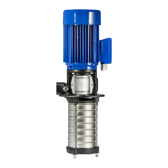
- Page 1 Vertical immersible multi-stage centrifugal pumps Installation and operating instructions Serie: DPVCI...
-
Page 2: Table Of Contents
Table of Contents 1: Manual Introduction Preface..............................4 Icons and symbols ..........................4 2: Identification, service and technical support Obtaining data and information ......................5 Seal codes ............................. 6 Current ..............................7 Supplementary documentation ......................7 3: Warranty Terms of warranty ..........................8 4: Safety and environment General .............................. - Page 3 10: Failures 10.1 Failure table ............................23 11: Annexes 11.1 EU declaration of conformity........................ 25 11.2 Certificate of Decontamination......................26...
-
Page 4: 1: Manual Introduction
Manual Introduction Preface READ THE (SUPPLEMENTARY) DOCUMENTATION Read the installation and operating This manual contains important information for instructions. reliable, proper and efficient operation. Compliance with the operating instructions is of vital importance to ensure reliability and a long service life of the product and to avoid any risks. -
Page 5: Obtaining Data And Information
The name plate indicates the type series / size, main operating data and identification number. Please DPVCI 15/17(19) B quote this information in all queries and/or repeat FRAME 160M (13.9 kW) 50 Hz orders. Particularly when ordering spare parts. If you... -
Page 6: Seal Codes
The following address data are available for service and technical support: DP-Pumps Tel: +31 172 488388 service department Internet: www.dp-pumps.com Kalkovenweg 13 E-mail: dp@dp-pumps.com 2401 LJ Alphen a/d Rijn The Netherlands Seal codes Table 2: Material code shaft seal Description Designation Code acc. -
Page 7: Current
Not only the motor, but also the pump has to be protected in its application. 2.3.1 Nominal current DPVCI 2, 4, 6, 10 & 15 Supplementary The nominal allowable current of the motor is stated on the motor plate. This shows the nominal working... -
Page 8: Terms Of Warranty
Warranty Terms of warranty The warranty period is settled by the terms of your contract or at least by the general terms and conditions of sales. ATTENTION Modifications or alterations of the product supplied are only permitted after consultation with the manufacturer. -
Page 9: 4: Safety And Environment
Safety and environment General ATTENTION Children being supervised not to play with the appliance. This DP-Pumps product has been developed using state-of-the-art technology and is manufactured with utmost care and is subject to continuous quality Users control. DP-Pumps does not accept any liability for damage or injury caused by not following the directions and All personnel involved in the operation, maintenance, instructions in this manual or by carelessness during... -
Page 10: Safety Precautions
Safety precautions Return to supplier • 4.4.1 During normal use Drain the pump. • • For questions regarding the power supply Always flush and clean the pump, particularly if it contact the local electricity company. has been used for handling noxious, explosive, •... -
Page 11: Unauthorised Modes Of Operation
ENVIRONMENTAL INSTRUCTION Ask at the local government about the re-use or the environmentally friendly processing of discarded materials. WEEE MARKING Electrical or electronic equipment marked with the adjacent symbol must not be disposed of in household waste at the end of its service life. -
Page 12: 5: Pump Introduction
Pump Introduction Model key Table 5: Model key Example DPVCI 15/17(19) B I 15 /17 (19) Label Product Label Material/Construction Cast Iron pump foot and top bracket hydr. 1.4301 / AISI 304 Connections 5/4” Inner thread Size (Capacity in m /h at Q. -
Page 13: Operation
Viscosity [cSt] 1-100 Density [kg/m 1000-2500 Cooling forced motor cooling Minimum frequency [Hz] Figure 4: DPVCI 15 Maximum frequency [Hz] Maximum number of starts up to 11 kW: 300 per hours other: 200 During centrifugal operation of the pump an negative pressure is created at the inlet of the impeller. - Page 14 If the ambient temperature exceeds the above value or the motor is located more than 1000 m above sea level, the motor cooling is less effective and could require an adapted motor power. See table 7: Motor load dep. sea level or amb. temp or please contact your supplier for more detailed advice.
-
Page 15: Transport
Transport Transport ID4051 Transport the pump in the position as indicated on the pallet or packaging. Make sure the pump is stable. If present, observe the instructions on the packaging. WARNING Lift the pump, if necessary using a hoist and suitable slings. Attach the slings to the transport lugs on the packaging, where present. -
Page 16: 7: Installation Instructions
Installation instructions Pump location Table 9: DPVCI 2-15 B / 15 C Dimensions DPVCI 2/4/6 B DPVCI 10/15 B WARNING DPVCI 15 C The pump must be installed so that G 5/4 persons cannot accidentally come into [mm] contact with hot surfaces. -
Page 17: Check Seal
Check seal 7.3.1 Indicators ID4141 ID4074 914.03 412.06 Figure 9: Seal Figure 8: Arrow rotation mark ID4075 The arrow on the motor stool indicates the rotating direction of the motor. 7.3.2 Install bypass 914.01 Install a bypass if the pump operates against a closed valve. -
Page 18: Mounting A Motor On The Pump
The motor has to conform to the following conditions: • Reinforced bearing at driven end (to withstand ID4141 the axial force) • Axially fixed rotor (to minimize the axial play of the pumps hydraulic) • Smooth shaft, no key lock (to improve the coupling grip and to improve the motor balance) 914.01 Figure 11: Step 2... -
Page 19: Electrical Installation
Electrical installation The advised bearings per motor type are: WARNING Table 11: Minimum required motor Driven-end In accordance with the local regulations bearing only authorised personnel is allowed to electrically connect the motor. Bearing type Power 1 phase 3 phase ATTENTION output 50 Hz... -
Page 20: Commissioning
If this doesn’t solve the shaft leakage, replacement of • that the pump body is partly filled with liquid the mechanical seal is necessary. (partly submerged) see figure 7: DPVCI 2-15 B / 15 C; • that the strainer is not blocked. -
Page 21: Operation
Operation Operation The pump is controlled externally and therefore does not need any operational guidance. -
Page 22: Introduction
Maintenance Introduction Drain each pump and/or the system. Remove all plugs from the pump. Disassemble the cartridge seal and check the WARNING running surfaces Observe the general safety precautions for installation, maintenance and repair. Regular maintenance is necessary for the correct operation of a pump. - Page 23 10 Failures 10.1 Failure table WARNING Observe the general safety precautions before install, maintenance and repair. Problem Possible cause Possible solution Checkpoints Leakage along the shaft. Running surfaces of the Replace the mechanical Check the pump for dirt - mechanical seal worn or seal.
- Page 24 Problem Possible cause Possible solution Checkpoints • Pump does not start. No voltage on the termi- Check the power supply. Circuit • nal clamps. Main switch • Fuses • Check the motor safety Earth leakage switch • relay Protective relay Thermal motor safety Reset the thermal motor- Check if the correct value...
- Page 25 Declares as the manufacturer in his own responsibility, that the products: Product: Vertical immersible multi-stage centrifugal pumps Series: DPVCI to which this declaration relates, are constructed in conformity with the following harmonized international standards: Serial number: 40/2021 1000000-1 - 52/2023 9999999-999...
- Page 26 11.2 Certificate of Decontamination Type: Order number: Delivery date: Applications: Fluid handled: Please tick where applicable: Corrosive Oxidising Flammable Explosive Hazardous to health Seriously hazardous Toxic Radioactive Bio-hazardous Safe to health Reason(s) for return: Comments: The product/accessories have been carefully drained, cleaned and decontaminated inside and outside prior to dispatch/placing at your disposal.
- Page 28 P.O. Box 28 2400 AA Alphen aan den Rijn The Netherlands t +31 172 48 83 88 dp@dp-pumps.com www.dp-pumps.com 2022-01 BE00000519-E / EN Can be changed without prior notice Original instructions...
Need help?
Do you have a question about the DPVCI and is the answer not in the manual?
Questions and answers