
Related Manuals for Flight Display Systems DAPS440

Summary of Contents for Flight Display Systems DAPS440
- Page 1 All manuals and user guides at all-guides.com DAPS440 Installation and Operation Manual Video/Audio Switcher TECHNICAL SUPPORT 678-867-6717, or www.FlightDisplay.com...
- Page 2 All manuals and user guides at all-guides.com DAPS440 Video/Audio Switcher © 2008 Flight Display Systems. All Rights Reserved. Flight Display Systems 1765 Grassland Parkway Alpharetta, GA 30004 678-867-6717 Phone 678-867-6742 Fax sales@flightdisplay.com www.flightdisplay.com For the most current copy of all product manuals, please visit our website at www.flightdisplay.com...
-
Page 3: Table Of Contents
All manuals and user guides at all-guides.com Table of Contents General Information Front View ......................5 Additional Information ................5 Specifications .....................6 Installation Instructions Power.......................6 Video Wiring Suggestions................7 S-Video/Composite and Audio Wiring.............7 Power and Ground Wiring ................7 ... -
Page 4: General Information
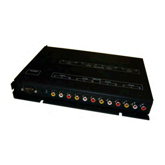
General Information The DAPS440 is a Video/Audio Switcher which takes 4 composite sources, and amplifies and switches each to 4 outputs. In addition, the DAPS440 supplies 3 Amps of 12VDC of power available for other cabin entertainment products (i.e. Wireless Audio, DVD player, Glareshield Camera, or LCD monitors). -
Page 5: Specifications
Section 21 Category B Installation Instructions All cabin entertainment equipment, such as the DAPS440, should be installed on a non-essential bus and have a dedicated circuit breaker. It is a requirement that a switch be installed so that the pilot can de-energize the system should it become necessary. -
Page 6: Video Wiring Suggestions
All manuals and user guides at all-guides.com DAPS440 Video Wiring Suggestions All shields should be grounded to the connector at the source, and floating at the display. Avoid routing video wiring parallel to: • AC wiring • Strobe wiring •... -
Page 7: Pinout For High Density Db-15
All manuals and user guides at all-guides.com Pinout for High Density DB-15 Part Numbers for DB-15 connectors, manufactured by Tyco or Amp. High density, D-sub, 15 contact receptacle (female) P/N 748565-1 HD15F pins P/N M39029/57-354 Wiring Diagram Description Number 28VDC Power In 28VDC Ground In 12VDC Power Out 12VDC Ground Out... -
Page 8: Troubleshooting
All manuals and user guides at all-guides.com DAPS440 Troubleshooting Video Noise Check for an incorrect ground in the installation wiring. See specific examples of video noise below, or visit http://flightdisplay.com/Grounding.pdf Snow or Sweeping Lines Lines that slowly sweep up and down are a result of AC noise. This AC noise can be generated by a power cart on the aircraft. -
Page 9: Technical Support
For further product information, technical data and sample wiring diagrams, please click on the Dealers section of our web site at www.flightdisplay.com Instructions for Continued Airworthiness The DAPS440 is designed not to require regular general maintenance. 10 Revision E, December 2009 ... -
Page 10: Warranty Information
867-6717 to obtain assistance. If the return of the unit to the factory is required, an RMA number will be issued at that time. Flight Display Systems will, upon receipt of the failed hardware, remanufacture or replace the unit at our discretion. -
Page 11: Assembly Drawing
All manuals and user guides at all-guides.com Assembly Drawing 12 Revision E, December 2009 ... -
Page 12: Index
All manuals and user guides at all-guides.com DAPS440 Index Coaxial Cable ........6 Shields..........6 Color Distortion.........8 Support ...........8, 9 Continued Airworthiness ....9 Warranty ..........10 DB-15...........7 Wiring ..........6 Flammability........6 Diagram..........7 Noise ...........8 Power and Ground ......6 Power ..........8 13 Revision E, December 2009... -
Page 13: Log Of Revisions
All manuals and user guides at all-guides.com Log of Revisions Date Page Description 01/25/2007 01/16/2008 Swapped pinout of Switch Inputs. 06/20/2008 Removed “Remote Control Inoperable” from troubleshooting 04/14/2009 6,11 Updated specifications, warranty info 12/11/2009 Revised Assembly Drawing 14 Revision E, December 2009 ...
Need help?
Do you have a question about the DAPS440 and is the answer not in the manual?
Questions and answers