Table of Contents
Advertisement
Quick Links
Advertisement
Table of Contents

Related Manuals for Lütze CPSB3-2400 Series

Summary of Contents for Lütze CPSB3-2400 Series
- Page 1 Operating instructions CPSB3-2400 High End Power Supply Version 2.0...
- Page 2 CPSB3-2400 - Operating instructions The company Friedrich Lütze GmbH reserves the right to make changes to its products in the interest of technical development. These changes are not necessarily documented in each individual case. This manual and the information contained herein have been compiled with due care. However, the company Friedrich Lütze GmbH accepts no liability for printing or other errors or resulting damage.
-
Page 3: Table Of Contents
CPSB3-2400 - Operating instructions Content Introduction .................. 6 General Information ..............7 2.1 Symbol Description ................... 7 2.2 Copyright ......................7 2.3 Disclaim of Liability.................... 7 Safety .................... 8 3.1 Content of the manual ..................8 3.2 Intended Use ..................... 8 3.3 Recipients ...................... - Page 4 CPSB3-2400 - Operating instructions 8.3.8 Auxiliary 12V/100mA output .................... 27 8.3.9 Auxiliary relay dry contacts ....................27 8.3.10 Connection to a PC through the USB communication box COMM BOX ..... 27 8.4 Maintenance ....................28 Operating modes ................ 29 9.1.1 Overboost mode (default) ....................
- Page 5 CPSB3-2400 - Operating instructions 10.6 Event log ......................43 10.6.1 Over Load error ......................44 10.6.2 Over Termperature error ....................44 10.6.3 Output Overvoltage error ..................... 44 10.6.4 Input Under Voltage error ..................... 44 10.6.5 Input Over Voltage error ....................45 10.6.6 PFC Under Voltage error .....................
-
Page 6: Introduction
CPSB3-2400 - Operating instructions 1 Introduction This manual is a component of the product: 2400 W High Efficiency Power Supply. These instructions must be read and understood before installing, operating, maintaining or dismantling the device. It contains important information about the handling and safety. Risk of injury and damage to equipment cause by non-observance of the operating instructions. -
Page 7: General Information
CPSB3-2400 - Operating instructions 2 General Information 2.1 Symbol Description The manual contains several safety messages. Each safety message contains a defined signal word and a color. The color and the word are referring to an alert level. There are 4 levels. The safety messages point out hazardous situations and give information to avoid those. -
Page 8: Safety
CPSB3-2400 - Operating instructions 3 Safety 3.1 Content of the manual Read and follow the manual before using the product the first time. This applies to every person which is getting in touch with the product. Trained employees and experts, especially qualified persons which had worked with similar products before, have to read and understand the manual. -
Page 9: Responsibility Of The Operator
CPSB3-2400 - Operating instructions Experts The employee has a technical education, knowledge and/or experience in the required field. The employee is capable to perform specific operations on and with the product. Qualified electricians The employee has a technical education in the required field. The employee is capable to perform special operations on and with the product. -
Page 10: Reconstruction And Modifications Of The Product
CPSB3-2400 - Operating instructions • Software-Version • Serial number 3.8 Reconstruction and Modifications of the Product Reconstructions and modifications of the product can cause property damages or personal injuries. Do not reconstruct the product if the manufacturer does not allow it explicit in writing. 3.9 Safety Arrangement Do not bypass protection equipment and safety arrangements. -
Page 11: Scope Of Delivery
CPSB3-2400 - Operating instructions 4 Scope of Delivery High end power supply CPSB3-2400-xx... -
Page 12: Transportation And Storage
CPSB3-2400 - Operating instructions 5 Transportation and Storage Protect the devices from moisture. Store the device in dry rooms between 0°C (32 °F) and 60°C (140°F). Make sure that the power supply is securely packed for transport. This is the only way to absorb shocks. -
Page 13: Product Overview
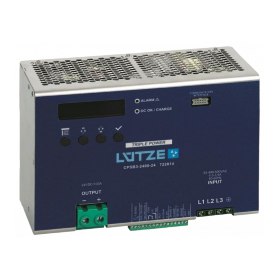
CPSB3-2400 - Operating instructions 6 Product Overview 6.1 Product description The CPSB3-2400x series is a high power, high performance, CPU controlled 3-phase input SMPS family. These products present many advanced features such as: ▪ Very high efficiency (>92%) ▪ Compactness ▪... - Page 14 CPSB3-2400 - Operating instructions Figure 1: Figure 1 shows a front view of the SMPS with a short description of the main elements Figure 2: Auxiliary connector I/Os...
-
Page 15: Functional Description
CPSB3-2400 - Operating instructions 7 Functional description A simplified block diagram of the CPSB3-2400 is shown in Figure 3. Figure 3: CPSB3-2400 simplified block diagram is a 3-phase input SMPS with 2 power stages, supervised by a microcontroller. The first CPSB3-2400 stage is a power factor corrector (PFC) module that improves unit efficiency and reduces the harmonic current from the mains. -
Page 16: Installing The Cpsb3-2400
CPSB3-2400 - Operating instructions 8 Installing the CPSB3-2400 8.1 General considerations CPSB3-2400 is a high voltage and high current SMPS. In order to avoid potentially hazardous situations including fire hazard, safety recommendations must be followed. Only authorized staff can install the unit. 8.1.1 Input voltage Vin= 3x400…500VAC (range=340…550VAC) or 520…750VDC. -
Page 17: Auxiliary Connector Wiring
CPSB3-2400 - Operating instructions 8.1.5 Auxiliary connector wiring The auxiliary terminal block accepts wires from 0.5mm (20AWG) to 1.5mm (15AWG). Strip the wire insulation for 5mm, screw tightening 0.25Nm, use only 60/75 Class 1 copper wires. 8.1.6 Cooling Mount the device in vertical position, keep at least 80mm (3inch) free spacing on upper and lower side, 10mm (0.4inch) free spacing between adjacent devices. -
Page 18: Mounting And Dismounting The Device
CPSB3-2400 - Operating instructions 8.2 Mounting and dismounting the device 8.2.1 Mounting the device Figure 4: Mounting the device on DIN rail Snap on the device on IEC60715/H35-7.5 rail; push the bottom side of the device towards the rail. The device will be automatically locked to the rail. -
Page 19: Connecting The Device
CPSB3-2400 - Operating instructions 8.3 Connecting the device 8.3.1 Standard connection Figure 6: Standard AC device connection... -
Page 20: Connection With Remote Voltage Sense
CPSB3-2400 - Operating instructions Figure 7: Standard DC device connection Check the polarity of the output load before applying mains. 8.3.2 Connection with remote voltage sense Figure 8: Connection using remote voltage sense... -
Page 21: Connection In Series
CPSB3-2400 - Operating instructions When the load is placed far away from the SMPS or when tight voltage accuracy is needed by the load, the provides a feature to compensate the output cables I*R voltage drop. It can CPSB3-2400x tightly regulate the output voltage directly at the load terminals and not at the SMPS output terminal, within 10mV of precision. -
Page 22: Connection Parallel (Power And Redundancy)
CPSB3-2400 - Operating instructions The series connection allows increasing the total output voltage. Connect the output terminals of each device in series checking the right polarity. Before any power ON be sure to have connected the antiparallel diodes to all units. The voltage rating of EACH diode should cover the TOTAL voltage of the SERIES system. - Page 23 CPSB3-2400 - Operating instructions The parallel connection may have one of the following purposes: Redundancy: several units (unlimited number in theory, 2...4 units in practice) can be used to increase the system reliability. If one SMPS fails the load will be still powered from another SMPS connected in parallel.
-
Page 24: Battery Charger Connection (Only On "-24", "-48" And "-72" Models)
CPSB3-2400 - Operating instructions Battery charger connection (only on “-24”, “-48” and “-72” models) 8.3.5 Figure 11: Connection when used as battery charger Both models of the switching power supply have a battery charging function ▪ CPSB3-24 12 V and 24 V Lead-based batteries with a capacity of 40 Ah to 1000 Ah. ▪... -
Page 25: Output Current Remote Measurement
CPSB3-2400 - Operating instructions Respect the battery polarity! The device is NOT protected against battery polarity reversal. A connection with wrong battery polarity will damage the device and generate a fire hazard. Battery charger function can be used ONLY in combination with battery. No loads are allowed to be connected to the battery terminals. -
Page 26: Remote Shutdown Input
CPSB3-2400 - Operating instructions 0…10V voltage output: 0V corresponds to 0A output, 10V corresponds to the rated output current of the SMPS. 4…20mA current output: 4mA corresponds to 0A output, 20mA corresponds to the rated output current of the SMPS. The 2 outputs are floating with respect to the SMPS output (opto-isolated), but their ground is common to GND AUX. -
Page 27: Auxiliary 12V/100Ma Output
CPSB3-2400 - Operating instructions External signal: when applying an external DC voltage as shown on Figure 14 from 5VDC to 24VDC to the SHUTDOWN inputs the CPSB3-2400 output will be turned ON or OFF depending on the programmed shutdown polarity (see §6.4.9). External switch or relay contact: by connecting an external switch or relay contact as indicated in Figure 15 the CPSB3-2400 output can be switched ON or OFF by only acting on the switch or relay contact. -
Page 28: Maintenance
CPSB3-2400 - Operating instructions Figure 16: Connection to the USB communication box The CPSB3-2400 is provided with a connector called communication interface where the USB communication box COMM BOX must be connected. This allows interacting with the device using a PC provided with USB interface and a specific PC application (“POWER MASTER”). -
Page 29: Operating Modes
CPSB3-2400 - Operating instructions 9 Operating modes CPSB3-2400 power supply has 3 different operating modes, user selectable (see §6.4.13). ▪ Overboost (OB) ▪ Constant current limit (CC) Battery charger (BC- available only on “-24”, “-48” and “-72” models) ▪ 9.1.1 Overboost mode (default) CPSB3-2400 in Overboost mode can provide a temporary power boost up to 150% (3600W) of its rated power for a maximum of 5 seconds. -
Page 30: Constant Current Limit Mode
CPSB3-2400 - Operating instructions 9.2 Constant current limit mode When operating in constant current limit mode CPSB3-2400 behaves as a constant voltage source or constant current source depending on the load. CC mode is suitable for powering loads that do not need high peak currents. -
Page 31: Battery Charger Mode (Available Only On "-24", "-48" And "-72" Models)
CPSB3-2400 - Operating instructions Battery charger mode (available only on “-24”, “-48” and “-72” models) 9.3.1 Lead acid and lithium iron phosphate (LiFePO4) Figure 19: Lead acid battery charging profile This operating mode performs lead-acid or lithium iron phosphate battery (LiFePO4) battery charging. The device has not any cell balancing circuit therefore LiFePO4 packs/batteries must been provided with management boards. -
Page 32: Revival Function
CPSB3-2400 - Operating instructions Constant voltage charge: during this phase the SMPS operates as a constant voltage source limited in current at 0.1C/0.2C or 0.17/0.33C (normal/fast charge) depending on battery technology previously described. The output voltage is kept constant at the value specified by column “Constant voltage” in Table 4. -
Page 33: Nickel (Nicd, Nimh)
CPSB3-2400 - Operating instructions 9.3.2 Nickel (NiCd, NiMH) Figure 20: Nickel battery charging profile This operating mode performs nickel battery charging, both NiCd and NiMH batteries can be charged. The charging algorithm is shown in Figure 20, 2 stages are implemented: Constant current charge: during this phase the SMPS operates as a constant current source limited at 0.1C or 0.2C with the maximum voltage limited to the “Battery charge voltage”... -
Page 34: User Interface
CPSB3-2400 - Operating instructions 10 User interface 10.1 Principles of operation An integrated user interface composed of an LCD (alphanumerical, 2 x 16 characters, with backlight), 2 status LEDs and 4 buttons is present on the CPSB3-2400. Through this interface the user can modify, monitor and control the SMPS behaviour. -
Page 35: Initial And Standard Screens
CPSB3-2400 - Operating instructions 10.3 Initial and standard screens Initial and standard screens are shown in Figure 22: Figure 22: User interface layout When the SMPS is energized a POWER ON TEST is performed and a specific screen is displayed. This test checks the digital controller. -
Page 36: Default Screen
CPSB3-2400 - Operating instructions 10.3.3 Default screen This is the screen that appears any time if there is no activity on the other menus for >1 minute. It shows the on going alarms (if present) or the on-line values of the main parameters of the unit. Error or Alarm type: Offending value: Line 1 shows the error or alarm type, while line 2 shows the offending value causing it. -
Page 37: Power Limit
CPSB3-2400 - Operating instructions Figure 23: Edit settings layout By pressing the OK button user can start editing the selected parameter. Editing is done by scrolling the possible values with the UP/DOWN keys. If the KEYS are kept pressed they auto repeats at an accelerating frequency. -
Page 38: Vin Min Alarm
CPSB3-2400 - Operating instructions 10.4.2 Vin min alarm Setting: Value: Use the UP/DOWN keys to select the minimum input voltage alarm threshold. Possible range is: 340 V < Vin min alarm < Vin max Alarm. Default: 340V 10.4.3 Vin max alarm Setting: Value: Use the UP/DOWN keys to select the maximum input voltage alarm threshold. -
Page 39: Date
CPSB3-2400 - Operating instructions 10.4.7 Date Setting: Value: Use the UP/DOWN keys to modify the date. Press OK or MENU key to advance the cursor to the next editable field, once the editable fields are finished press one more time to save and return to previous menu. -
Page 40: Operating Mode
CPSB3-2400 - Operating instructions Use the UP/DOWN key to select the desired input wiring between 3-PHASE and 2-PHASE. In 2- PHASE the maximum output power is limited to 1200W. Default: 3-PHASE 10.4.13 Operating mode Setting: Value: Use the UP/DOWN key to select the desired operating mode between OVERBOOST / CURRENT LIMIT / BATTERY CHARGER (battery charger only available on the “-24”, “-48”... -
Page 41: Battery Charge Mode (Only On "-24", "-48", And "72" Models)
CPSB3-2400 - Operating instructions battery capacity based on chemistry. The lead acid and nickel batteries share the same maximum capacities. Default: 50Ah / 25Ah / 15Ah (model dependent) Battery charge mode (only on “-24”, “-48”, and “72” models) 10.4.18 Setting: Value: This submenu is present only if operating mode is set to BATTERY CHARGER. -
Page 42: Lock Settings
CPSB3-2400 - Operating instructions 10.4.24 Lock settings Setting: Value: Used to lock the settings editing in order to avoid unintentional changes. Use UP/DOWN key to enable/disable the function. When enabled any attempt to change parameters will show a “Settings locked” message followed by the current parameter value. Keeping pressed at the same time for at least 3 seconds the up and down button while on “Edit settings”... -
Page 43: Measurement Accuracy
CPSB3-2400 - Operating instructions 10.5.5 Measurement accuracy Measure 24V model 48V model 72V model 170V model Input voltage ±5% ±5VAC Output voltage ±1% ±1% ±1% ±1% ±0.3V ±0.6V ±0.9V ±1.8V Output current ±2% ±3% ±3% ±4% ±2A ±2A ±2A ±2A Remote output ±5% ±2A current:... -
Page 44: Over Load Error
CPSB3-2400 - Operating instructions Code Name Condition Rem. ShDown Remote Shutdown Remote Shutdown activated Power ON Power ON SMPS powered ON BC CC Battery Charger Constant Current Battery starts Constant Current phase BC CV Battery Charger Constant Voltage Battery start Constant Voltage phase BC Float Battery Charger Float... -
Page 45: Input Over Voltage Error
CPSB3-2400 - Operating instructions 10.6.5 Input Over Voltage error Code, Type, Offending value: Time stamp: Event: Vin > 530VAC. The SMPS remains switched off until Vin is decreased below 520VAC 10.6.6 PFC Under Voltage error Code, Type, Offending value: Time stamp: Event: VPFC <... -
Page 46: Over Load Alarm End
CPSB3-2400 - Operating instructions 10.6.11 Over Load alarm end Code, Type, Maximum value: Time stamp: Event: Over Load condition alarm ends. Maximum value is the highest Iout measured during the alarm. 10.6.12 Over Temperature alarm start Code, Type, Offending value: Time stamp: Event: Transformer temperature >... -
Page 47: Phase Loss Alarm Start
CPSB3-2400 - Operating instructions 10.6.18 Phase Loss alarm start Code, Type: Time stamp: Event: A mains phase is missing for > 10s. In case of a phase loss alarm the maximum output power is reduced an half. 10.6.19 Phase Loss alarm end Code, Type: Time stamp: Event: Phase Loss alarm condition ends. -
Page 48: Battery Charger Constant Current Event
CPSB3-2400 - Operating instructions 10.6.25 Battery Charger Constant Current event Code, Type: Time stamp: Event: In BC mode the unit started the constant current phase (see §5.3). 10.6.26 Battery Charger Constant Voltage event Code, Type: Time stamp: Event: In BC mode the unit started the constant voltage phase (see §5.3). 10.6.27 Battery Charger Float event Code, Type:... -
Page 49: Information
CPSB3-2400 - Operating instructions 10.7 Information Factory set generic information (ID, etc.) is available under this menu. The UP/DOWN keys are used to scroll between the pages. 10.7.1 Model Item: Model code: 10.7.2 Serial Number Item: Serial number: 10.7.3 Firmware Item: Firmware version: 10.7.4... - Page 50 CPSB3-2400 - Operating instructions Minimum mounting clearances are shown on Figure 24. Figure 24: Minimum mounting clearance SMPS dimensions are shown on Figure 25...
- Page 51 CPSB3-2400 - Operating instructions Figure 25: Dimensions...
-
Page 52: Service
CPSB3-2400 - Operating instructions 11 Service If you have any further questions regarding the product or our repairing service, please contact us: Friedrich Lütze GmbH Bruckwiesenstraße 17-19 71384 Weinstadt Germany Tel.: +49 7151 6053-0 Fax: +49 7171 6053-277 info@luetze.de www.luetze.com... -
Page 53: Revision Of The Document
CPSB3-2400 - Operating instructions 12 Revision of the Document Version Revision Date 1.00 Final Review 07/2012 2.00 Addition in chapter Battery charger connection (8.3.5). Change 08/02/2021 from Lütze Transportation to Friedrich Lütze GmbH. Name change from NSP2400 to CPSB3-2400x. -
Page 54: Acronyms
CPSB3-2400 - Operating instructions 13 Acronyms Acronym Definition SMPS Switching Mode Power Supply. COMM BOX CPSB3-2400 Communication board. Used to interface a PC to the SMPS. Power Factor Corrector Protective Earth SELV Safety Extra Low Voltage PELV Protective Extra Low Voltage Firmware...
Need help?
Do you have a question about the CPSB3-2400 Series and is the answer not in the manual?
Questions and answers