Table of Contents
Advertisement
Quick Links
Advertisement
Table of Contents

Related Manuals for Addvalue Innovation wideye SABRE RANGER 5000

Summary of Contents for Addvalue Innovation wideye SABRE RANGER 5000
- Page 1 SABRE™ RANGER 5000 Date 20 November 2020...
-
Page 2: Table Of Contents
This manual is protected under international copyright laws. No part of this manual may be reproduced, distributed, translated, or transmitted in any form or by any means, electronic or mechanical, including photocopying, recording, or storing in any information storage and retrieval system, without the prior written permission of Addvalue Innovation Pte Ltd. -
Page 3: Introduction
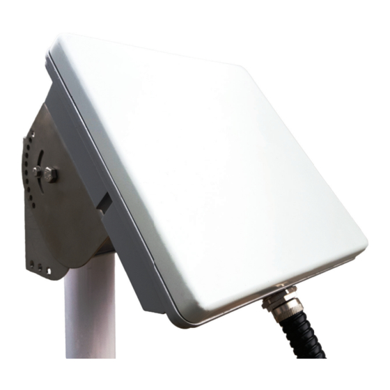
You can use either the rugged mounting bracket (optional accessory) of the Sabre™ Ranger 5000 (See fi gure 1 below.) or a VESA MIS-D bracket to mount the SABRE™ RANGER 5000 terminal. Figure 1 © 2020 Addvalue Innovation Pte Ltd. All rights reserved. -
Page 4: Quick Reference
The SABRE™ RANGER 5000 has a NPT ¾ inch hole for installing a conduit-fitting or a cable gland at the bottom part of the casing to route all the wires. NOTE: The mounting bracket is an optional accessory. © 2020 Addvalue Innovation Pte Ltd. All rights reserved. -
Page 5: Install The Sim Card
3. Open the SIM card cover and rotate in a clockwise direction. See fi gure 4. 3. Open the SIM card cover and rotate in a clockwise direction. See fi gure 4. Figure 4 © 2020 Addvalue Innovation Pte Ltd. All rights reserved. - Page 6 4. Slot the SIM card into the SIM card holder in the orientation as shown on figure 5. Figure 5 5. Insert the SIM card until it ‘clicks’ into place. 6. Rotate and move the SIM card cover back in place. © 2020 Addvalue Innovation Pte Ltd. All rights reserved.
-
Page 7: Connect The Cables And Wires
Figure 6 RS232/TX RS232/CTS GND RS232/RX RS232/RTS RS485/Z(B) RS485/B RS485/A RS485/Y(A) Analog Local RS232/ RS232/ Input Wakeup Figure 7 CON801 and CON802 Terminal Block Assignment © 2020 Addvalue Innovation Pte Ltd. All rights reserved. - Page 8 (-) marking. Press and hold the orange tab on the terminal block while inserting the wire into the hole. NOTE: The sample wires below are used for reference. You may use different colour wires that met the electrical specifications. © 2020 Addvalue Innovation Pte Ltd. All rights reserved.
- Page 9 NOTE: The sample wires below are used for reference. You may use different colour wires that met the electrical specifications. Black wire - terminal block 22 (GND) Red wire - terminal block 24 (RS232-TX) White wire - terminal block 23 (RS232-RX). Figure 10 © 2020 Addvalue Innovation Pte Ltd. All rights reserved.
- Page 10 NOTE: If you use the Belden cable no. 9535 for 5-wire RS232 (RX, TX, RTS, CTS, GND), refer to fi gure 7 for the wire connections to the terminal block. Figure 11 © 2020 Addvalue Innovation Pte Ltd. All rights reserved.
- Page 11 14(OP1) and pin 15(OP2) of CON801 and pin 2(OP3) and pin 3(OP4) of CON802. A low side driver will pull the signal to ground when active. An output can sink up to 400mA of current. Figure 12 © 2020 Addvalue Innovation Pte Ltd. All rights reserved.
- Page 12 Use Belden cable no. 9841 or equivalent. The analogue input is connected to pin 20 (Analog-input) of CON801. This input will accept a signal of 0V to 32VDC. The analogue signal ground is connected to pin 19 (GND) of CON801. © 2020 Addvalue Innovation Pte Ltd. All rights reserved.
- Page 13 Figure 14 3. Secure the wires together with a cable tie. 3. Secure the wires together with a cable tie. 3. Secure the wires together with a cable tie. Figure 15 © 2020 Addvalue Innovation Pte Ltd. All rights reserved.
- Page 14 NOTE: For ingress protection, it is important to ensure the screws are tightened to a torque value of 0.57 Nm (5.0 in-lbs), approximately 2 ½ to 3 turns for each screw. Figure 17 © 2020 Addvalue Innovation Pte Ltd. All rights reserved.
-
Page 15: Optional Accessories
Bracket Wall (185 x 90 x 100)mm Split Washers, M8 Socket Head Cap Screws, M8 x 14mm Bracket Body (189 x 110 x 90)mm Wing Screw, M5 x 12mm Spare kit ( © 2020 Addvalue Innovation Pte Ltd. All rights reserved. -
Page 16: Fix Optional Mounting Bracket To Sabre™ Ranger 5000
3. Align the four holes, and fasten to Sabre™ Ranger 5000 terminal using the washers (4x) and the socket head cap screws (M8 x 14mm - 4x) with a hex L-key. © 2020 Addvalue Innovation Pte Ltd. All rights reserved. -
Page 17: Mount The Terminal On A Pole
NOTE: The mounting bracket is designed to be mounted on a 1 to 3 inch diameter pole. 2. Use the supplied washers, socket head cap screws (M8 x 120mm), and the saddle clamps to mount the pre-assembled terminal on the pole. © 2020 Addvalue Innovation Pte Ltd. All rights reserved. - Page 18 See fi gure 21. Figure 21 4. Tighten the screws to secure the SABRE™ RANGER 5000 terminal to the pole. 5. Secure the conduit to the pole by using several cable ties. Figure 22 © 2020 Addvalue Innovation Pte Ltd. All rights reserved.
-
Page 19: Terminal Grounding
1. Unscrew one of the four mounting screws at the back of the terminal. 2. Insert the earth grounding wire lug in between the mounting bracket and the washer, and then tighten the screw. NOTE: Please seek professional local advice for earth grounding. © 2020 Addvalue Innovation Pte Ltd. All rights reserved. -
Page 20: Point The Antenna
5°. See fi gure 25 below. The terminal is at a vertical position at the angle of 0° and at a horizontal position at the angle of 90°. © 2020 Addvalue Innovation Pte Ltd. All rights reserved. - Page 21 SABRE™ RANGER 5000 Quick Start Guide Figure 25 4. Insert the M5 wing screw to lock the required position and tighten it to secure the angle of elevation. See fi gure 26. Figure 26 © 2020 Addvalue Innovation Pte Ltd. All rights reserved.
-
Page 22: Navigate To The Web Console
LEDs. Press and hold Pointing Mode button for more than 3 seconds to disable the Auto network registration mode and go to the manual network registration mode Figure 28 Figure 28 © 2020 Addvalue Innovation Pte Ltd. All rights reserved. - Page 23 NOTE: indicates fl ashing green LED and indicates steady green LED. Global Beam Signal Strength LEDs Signal (dB) 0 – 40 41 – 47 55 and above © 2020 Addvalue Innovation Pte Ltd. All rights reserved.
- Page 24 Figure 29 NOTE: Web Console will remind the user to change the password for the first time login for security purposes. A minimum of 6 characters are required for the new password. © 2020 Addvalue Innovation Pte Ltd. All rights reserved.
- Page 25 When the terminal is powered up while it is already pointed to the satellite, it will register to the network automatically. The LEDs will flash from right to left. When the network registration is successfully completed, all the LEDs will flash twice and turn off. © 2020 Addvalue Innovation Pte Ltd. All rights reserved.
-
Page 26: Appendix A: Terminal Block Pin Assignment
SABRE™ RANGER 5000 Quick Start Guide 11. APPENDIX A: TERMINAL BLOCK PIN 11. APPENDIX A: TERMINAL BLOCK PIN ASSIGNMENT ASSIGNMENT RS232/TX RS232/CTS RS232/RX RS232/RTS RS485/Z(B) RS485/B RS485/A RS485/Y(A) Analog Local RS232/RX RS232/TX Input Wakeup Figure 31 © 2020 Addvalue Innovation Pte Ltd. All rights reserved. - Page 27 DIGITAL INPUT 1 Max +32V IP 2 DIGITAL INPUT 2 Max +32V GROUND Analog Input Max +32V Local Wakeup Max +32V GROUND RS232/RX Debug Log Output only RS232/TX Debug Log Output only © 2020 Addvalue Innovation Pte Ltd. All rights reserved.
-
Page 28: Appendix B: Conduit & Accessories
1200232 NW23 Black PA6 corrugated pipe ID23.2 X OD28.9 mm 3805013 M25 male straight connector, black PA6 c/w gasket IP65 7211977 Black PA6 M25 locknut 6402212 Nickel Plated Brass Adaptor male NPT ¾” female M25 Figure 32 © 2020 Addvalue Innovation Pte Ltd. All rights reserved. -
Page 29: Appendix C: Technical Summary
OS Agnostic (supports access via Web-MMI) Environmental Operating Temp: -40ºC to +75ºC Operating Humidity: 95% (Condensing at 40ºC) Storage Temp: -40ºC to +80ºC Storage Humidity: 5% to 95% (RH) Water & Dust: IP66 compliant © 2020 Addvalue Innovation Pte Ltd. All rights reserved. - Page 30 Inmarsat Type Approval Whilst the above information has been prepared by Addvalue Innovation Pte Ltd (“Addvalue”) in good faith, and all reasonable efforts have been made to ensure its accuracy, Addvalue makes no warranty or representation as to the accuracy, completeness or fitness for purpose or use of the information.
- Page 32 Part Number: 74B00140002...
Need help?
Do you have a question about the wideye SABRE RANGER 5000 and is the answer not in the manual?
Questions and answers