Table of Contents
Advertisement
Advertisement
Table of Contents

Related Manuals for jotron Tron AIS-SART


Summary of Contents for jotron Tron AIS-SART
- Page 1 Tron AIS-SART AIS Transmitter User Manual...
- Page 2 This page is intentionally left blank...
- Page 3 International Telecommunication Union Light Emitting Diode EU Marine Equipment Directive Megahertz SART Search and Rescue Transponder SOLAS Safety of Life at Sea (An international maritime safety treaty) Very High Frequency jotron.com Doc. No.: 85355 Rev. H Page 3 of 48...
-
Page 4: Table Of Contents
8.3.1 Reception - non AIS-SART compliant transponder 8.3.2 Reception - non AIS-SART compliant (ECS/ECDIS) 8.3.3 Reception - AIS-SART compliant transponder ..33 8.3.4 Reception - AIS-SART compliant (ECS/ECDIS) ..34 jotron.com Doc. No.: 85355 Rev. H Page 4 of 48... - Page 5 14.1 Counterfeit spare parts ............. 45 15 Recycling and disposal ............... 45 16 Warranty ..................45 17 Service ..................45 17.1 Service agents ..............46 18 Document revision log ............... 47 jotron.com Doc. No.: 85355 Rev. H Page 5 of 48...
-
Page 6: List Of Figures
Figure 14 Illustration: Mounting on a pipe ........... 23 Figure 15 Illustration: Mounted ready on a pipe ......... 23 Figure 16 Illustration: Placing the Tron AIS-SART into the lifeboat bracket 24 Figure 17 Illustration: using the lanyard on a lifeboat ......... 25 Figure 18 Image: Tron AIS-SART with Liferaft mounting strap attached .. - Page 7 Figure 32 Image: Green LED ................. 36 Figure 33 Image: Red LED ................37 Figure 34 Image: Tron AIS-SART - Test instruction label ......38 Figure 35 Image: Display - Non-compliant AIS transponder ......39 Figure 36 Image: Text message display - Non-compliant AIS transponder . 39 Figure 37 Image: Display - ECS/ECDIS ............
-
Page 8: List Of Tables
Table 1 LED indicator functions ..............17 Table 2 List of components - lifeboat bracket ..........21 Table 3 Maintenance requirements ............. 35 Table 4 Tron AIS-SART error code descriptions – red flash during testing .. 37 jotron.com Doc. No.: 85355 Rev. H... -
Page 9: General
General Jotron manufactures safety products designed for the search and rescue of human lives and property. For this product to be effective according to the design parameters, it is imperative that it is handled, maintained, serviced and stowed in accordance with this manual. -
Page 10: Standards
Standards Jotron declares that this this product is compliant in accordance with IMO, SOLAS and GMDSS regulations. A copy of the declaration of conformity can be downloaded from jotron.com. The Tron AIS-SART has been verified, tested, and meets the following... - Page 11 SOLAS (74 amended) This regulation applies to ro-ro Chapter III Regulation 26. passenger ships. Additional requirements SOLAS (74 amended) Required radio communication Chapter IV, Regulation 7.1.3 equipment on mobile offshore units. jotron.com Doc. No.: 85355 Rev. H Page 11 of 48...
-
Page 12: Product Description
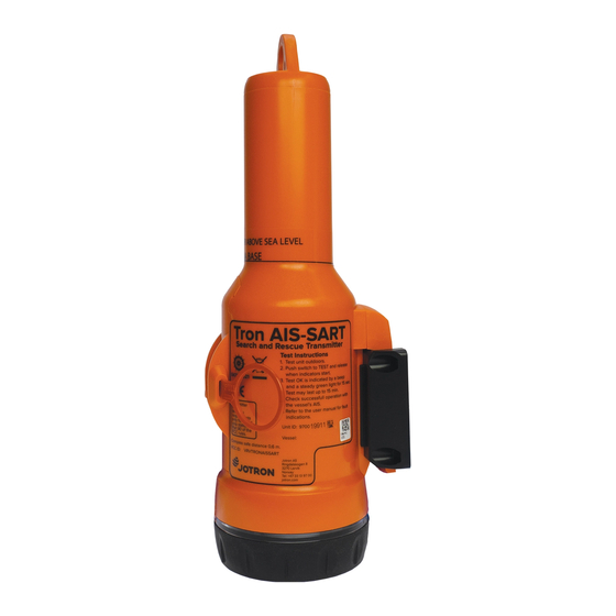
It is water, oil and sunlight resistant. An AIS search and rescue transmitter is a location device. The purpose of the Tron AIS-SART is to assist a seafarer in distress during a search and rescue operation. The Tron AIS-SART is designed for easy operation, it is buoyant and can withstand a drop of 20 meters into water. - Page 13 Figure 1 Tron AIS-SART jotron.com Doc. No.: 85355 Rev. H Page 13 of 48...
-
Page 14: Functional Description
Functional description Tron AIS-SART consists of a housing sealed at the lower end with a bottom lid. It may be split into the following main parts: • Transmitter module • Battery module • Bottom lid • LED indicator Figure 2 Illustration: Tron AIS-SART disassembled... -
Page 15: Battery Module
Battery module The battery module consists of two C-size lithium batteries, a battery house and connector and cables. A battery expiry label on the Tron AIS-SART housing displays the expiry date. A new battery comes complete with cable and connector. -
Page 16: Bottom Lid
Figure 5 Illustration: Battery label on housing The battery module is to be replaced every 5 years. Only original Jotron batteries can be used with this product. Figure 6 Illustration: Battery module (no cable or connector) Bottom lid The bottom lid includes four items: 1. -
Page 17: Led Indicators
Figure 7 Illustration: Bottom lid LED indicators Tron AIS-SART is equipped with two coloured LED indicator lights, one green and one red. The LED indicators provide a visual status of the operation (active) and faults (errors). In addition, a built-in buzzer beeps regularly when in operation. -
Page 18: Installation
Lifeboat bracket (with or without a pipe clamp) 7.1.1 Mounting the wall bracket A wall bracket is delivered with the Tron AIS-SART and should be used for storage of the unit. The bracket should be mounted in a vertical position and placed where the Tron AIS-SART is easily available in the case of an emergency. - Page 19 Figure 8 Illustration: Wall bracket dimensions Figure 9 Illustration: Tron AIS-SART mounted in wall bracket jotron.com Doc. No.: 85355 Rev. H Page 19 of 48...
-
Page 20: Mounting A Lifeboat Bracket
This bracket can be mounted either on a wall or a pipe. The Tron AIS-SART must not be permanently stored in this bracket if mounted outside a freefall lifeboat. Move the Tron AIS-SART to this bracket after the lifeboat is deployed in water. jotron.com Doc. No.: 85355 Rev. H... - Page 21 Screw, DIN 965 – Pozidrive M6x90 M-84838 Pipe clamp M-84875 Washer plate M-91469 Nu nylock M6 DIN 985 M-82275 Washer, DIN 9021 – Ø6mm Table 2 List of components - lifeboat bracket jotron.com Doc. No.: 85355 Rev. H Page 21 of 48...
- Page 22 Use the following dimensions when mounting the lifeboat bracket on a wall. Figure 12 Illustration: Lifeboat bracket dimensions Figure 13 Illustration: Mounting - interior/exterior wall jotron.com Doc. No.: 85355 Rev. H Page 22 of 48...
- Page 23 The lifeboat bracket fits a pipe with a maximum diameter of 50mm. Figure 14 Illustration: Mounting on a pipe Figure 15 Illustration: Mounted ready on a pipe jotron.com Doc. No.: 85355 Rev. H Page 23 of 48...
-
Page 24: Non Bracket Mounting Options
• Telescopic pole 7.2.1 Mounting the lanyard The lanyard can be used to hang the Tron AIS-SART inside a liferaft. Any objects that the lanyard can be attached to can be used. The lanyard is 10 meters in length. Keep the Tron AIS-SART away from any metal objects. -
Page 25: Mounting The Liferaft Mounting Strap
Figure 17 Illustration: using the lanyard on a lifeboat 7.2.2 Mounting the Liferaft mounting strap The Liferaft mounting strap can also be used to attach the Tron AIS-SART to an inflatable canopy. To use the Liferaft mounting strap, do the following: 1. -
Page 26: Mounting The Telescopic Pole
Figure 18 Image: Tron AIS-SART with Liferaft mounting strap attached 7.2.3 Mounting the telescopic pole A telescopic pole can be used to extend the height of the Tron AIS-SART inside or outside the lifeboat/liferaft. Ensure the rod is held as vertical as possible when activating the Tron AIS-SART. -
Page 27: Replacing The Battery Module
Figure 19 Illustration: Tron AIS-SART with telescopic pole attached Figure 20 Illustration: using the telescopic pole on a lifeboat Replacing the battery module Below describes how to change the battery on the Tron AIS-SART. 7.3.1 Disassembly To disassemble the battery module, do the following: 1. -
Page 28: Assembly
4. Remove the two old 5gram silica gel bag. 7.3.2 Assembly To assemble the battery module, do the following: 1. Install the new battery, verify the cable is within the guide. jotron.com Doc. No.: 85355 Rev. H Page 28 of 48... - Page 29 5. Remove old O-ring (using for example a plastic card). Use Vaseline (acid free) and fit a new O-ring in place. 6. Reinstall the lid (tighten by hand), then replace the rubber holder. jotron.com Doc. No.: 85355 Rev. H Page 29 of 48...
-
Page 30: Operating Instructions
Operating instructions Figure 21 Image: Tron AIS-SART operating instructions label The Tron AIS-SART should only be used in an emergency. The battery lasts for 96 hours from activation. Replace the battery if the unit is used for any purpose other than a test. -
Page 31: Activation
The LED indicator starts to flash and the unit beep regularly. 3. Secure the Tron AIS-SART to the lifeboat/liferaft in a vertical position and as high as possible. 4. Both LEDs (green & red) will flash while the unit is searching to fix a GPS position (max. -
Page 32: Deactivation
This type of AIS transponder will appear as a vessel without a name, but with MMSI (ID code), range, bearing and position. In addition, a text message stating SART ACTIVE will also be received. jotron.com Doc. No.: 85355 Rev. H Page 32 of 48... -
Page 33: Reception - Non Ais-Sart Compliant (Ecs/Ecdis)
The text SART ACTIVE appears as the vessel name showing range, bearing and position. In addition, a text message stating SART ACTIVE will also be received. jotron.com Doc. No.: 85355 Rev. H Page 33 of 48... -
Page 34: Reception - Ais-Sart Compliant (Ecs/Ecdis)
Once acknowledged, the symbol shall cease flashing. Figure 30 Image: Display - Electronic chart - Red symbol and dashed line A text message stating SART ACTIVE will also be received. jotron.com Doc. No.: 85355 Rev. H Page 34 of 48... -
Page 35: Maintenance
Table 3 Maintenance requirements Testing Although the Tron AIS-SART does not send an alarm via satellite, VHF or other radio communication, usage should be limited to short tests. This ensures the best battery capacity available for a potential emergency. - Page 36 The Tron AIS-SART will now run through a self-test procedure. If a RED LED flashes, it indicates a critical fault. Refer to the error codes for more information. 2. Release the switch when both LEDs start flashing. The unit will now search for the GPS position.
-
Page 37: Error Codes (Red Flash During Testing)
Transmit frequency error User ID not programmmed Undefined, contact Jotron Internal communication error Table 4 Tron AIS-SART error code descriptions – red flash during testing Test procedure instructions are also indicated on the product label. jotron.com Doc. No.: 85355 Rev. H... -
Page 38: Test Reception On Nearby Vessels, Ais Transponders And Ecs/Ecdis Or Chat Plotters
ECS/ECDIS or chat plotters To conduct a complete test of a Tron AIS-SART, reception on the ships AIS transponder should also be checked. Some AIS transponders are not compliant with AIS-SART, but will still receive them as another ship, both with ID code, position, range, bearing and text message. -
Page 39: Reception On A Non Ais-Sart Compliant Ais
9.3.2 Reception on a non AIS-SART compliant electronic chart (ECS/ECDIS) This will be shown as a ship. The same text message will be received stating: SART ACTIVE. Figure 37 Image: Display - ECS/ECDIS jotron.com Doc. No.: 85355 Rev. H Page 39 of 48... -
Page 40: Reception On An Ais-Sart Compliant Ais
There shall be a separate menu item in the AIS to activate reception of the AIS-SART in TEST. Jotron TR-8000: Advanced - VHF Link/Long range – Display SART in test mode Furuno FA-150 implementation – USER SETTINGS – DISP SART TEST = ON... -
Page 41: Reception On An Ais-Sart Compliant Electronic Chart (Ecs/Ecdis)
Once acknowledged, the symbol shall cease flashing. Figure 39 Image: Display - Electronic chart - Red symbol and dashed line A text message stating SART TEST will also be received. jotron.com Doc. No.: 85355 Rev. H Page 41 of 48... -
Page 42: Test And Maintenance Records
Test and maintenance records Below is an overview of all test and control details. Date B/T* Signature Inspector name *B=New battery, T=Test jotron.com Doc. No.: 85355 Rev. H Page 42 of 48... -
Page 43: Battery Safety Information
The safety information is available for download at jotron.com - product. http://jotron.com/product/tron-ais-sart/. 11.1 Handling and storage This product should be stored in a cool and well-ventilated area. Elevated temperatures can result in a reduction of battery life. -
Page 44: Technical Specifications
Antenna pattern: Vertical polarization 12.3 Brackets 12.3.1 Wall bracket Materials: ASA (acrylonitrile styrene acrylate) Bracket (incl. unit) (H/W/D): 250mm x 89mm x 90mm Weight: 20grams 12.3.2 Lifeboat bracket Materials: Anodized aluminum jotron.com Doc. No.: 85355 Rev. H Page 44 of 48... -
Page 45: Optional Accessories
Service All services such as testing, installation, programming, replacement, marking and battery exchange are provided by an authorized Jotron service agent. Improper service or maintenance may destroy the functionality and/or performance of this product. -
Page 46: Service Agents
Jotron does not accept any responsibility for the dismantling or reassembling of any Jotron product that occurs externally from a Jotron authorized facility and/or is handled by someone other than an authorized, trained and certified person. 17.1 Service agents Refer to jotron.com... -
Page 47: Document Revision Log
21.04.10 Updated information (34 pages) 10.06.10 Updated information (page 28) 29.08.12 Updated information (36 pages) 21.12.21 Updated content, revised text structure and and new documentation design and layout in accordance with new company profile. jotron.com Doc. No.: 85355 Rev. H Page 47 of 48... - Page 48 NORWAY / HEADQUARTERS CHINA Jotron AS Jotron USA, Inc Norway Jotron AS Beijing Ringdalskogen 8 6300 Rothway Street, Suite C Representative Office (ATC business) 3270 Larvik, Norway Houston, TX 77040, USA No. 1204 room, building D Tel: +47 33 13 97 00...
Need help?
Do you have a question about the Tron AIS-SART and is the answer not in the manual?
Questions and answers