Table of Contents
Advertisement
Quick Links
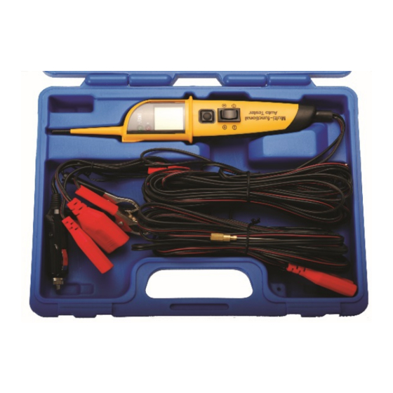
DIGITAL Multifunction Voltage Tester
INTRODUCTION
This is an equipment used to test the automotive electrical system within 12-24 volts. In order to save
the testing hours for the automotive electrical system, it is designed to testing the system without re-
connection between the vehicle battery and the testing components.
FUNCTIONS
Determine the polarity and circuit circumstance (short/ open).
•
Activating the components with positive or negative current without jumper wire.
•
Testing the voltage and continuity of the circuit.
•
Illumination.
•
Locate missing cylinders.
•
Measuring frequency of the high-tension ignition pulses and we could calculate the rotational
•
speed of engine according to the measured frequency.
Peak detection.
•
Testing the voltage of the circuit and the voltage reading will be indicated on the LCD display
•
within 1/10 of a volt.
WARNING
When current is provided to the unit, spark may be occurred when the tip contacts with ground or
•
certain circuits. Therefore please do not operate it around flammable.
Do not operating it with 110/220 volt house voltage as it is only for 12-24 volt system
•
Important: Read these instructions before using the device for the first time.
•
Be sure where you are testing, when applying positive and negative potential, components such
•
as Control module, potentiometer, etc. can be destroyed.
Manual transmissions always idle and automatic transmissions always insert "P". Faulty
•
measurements at the starter can be accidentally activated and can property damage and serious
injury.
Be careful when using the extended test tip, short circuit risk, because they are not isolated.
•
SW-Stahl und Werkzeugvertriebs GmbH
L
e
v
e
k r
u
s
r e
t S
a r
s
s
e
6
5
D
4 -
2
8
9
7
R
e
m
s
c
h
e
d i
Tel. +49 (0) 2191 / 46438-0
F
ax +49 (0) 2191 / 46438-40
- E
M
a
: l i
n i
o f
@
s
w
s
a t
l h
d .
e
Art. 40105
Advertisement
Table of Contents

Subscribe to Our Youtube Channel
Related Manuals for BGS technic 40105


Summary of Contents for BGS technic 40105
- Page 1 Art. 40105 DIGITAL Multifunction Voltage Tester INTRODUCTION This is an equipment used to test the automotive electrical system within 12-24 volts. In order to save the testing hours for the automotive electrical system, it is designed to testing the system without re- connection between the vehicle battery and the testing components.
- Page 2 COMPONENTS Ground testing Probe Light lead Display Car socket Battery clamp Extension Battery Polar clamp switch Range switch If you use the unit “Polar switch” to test, please add extended-probe to its probe. As shown in the figure For example: 1.
-
Page 3: Mode Instruction
MODE INSTRUCTION It have four modes, the four modes can be selected by depressing the mode select button and cycling through each one. MODUS Voltage tester Measuring range: 0 to 60V Ignition voltage measuring range Voltage is shown in KV Measuring frequency Value is shown in Hertz (Hc) Peak Detection... -
Page 4: Polarity Test
SELF-TEST If it is working correctly, the condition should be followed: Red LED should be on when the technician push the polar switch forward (toward the positive side). Green LED should be on when the technician push the polar switch backward. (toward the negative side). - Page 5 ACTIVATE THE COMPONENTS WITH AUTOMOTIVE ELECTRICAL SYSTEM DISCONNECTED By assisting its tip with the ground test lead, technician can activate the testing components with automotive electrical system been disconnected. This function can be used to test light, cooling fans, and fuel pumps etc. To do this, please follow the procedure 1.
-
Page 6: Voltage Test
ACTIVATE THE COMPONENTS WITH NEGATIVE VOLTAGE ONLY Apart from applying the positive voltage, technician can also use this unit to provide negative voltage to the components. The procedures are as follow: 1. Contact its tip to the negative pole of the component; at this stage, the red LED should be on if the component working correctly. -
Page 7: Measuring Method
LOCATE MISSING CYLINDERS Placing its probe tip next to a sparking wire (DON’T probing it directly), through capacitive coupling, it can see the high-tension ignition pulses at the same time display a voltage reading. By monitoring each plug wire in this way you can locate missing cylinders. WARNING Do not contact probe tip directly to the secondary ignition circuit! Do not touch the primary or secondary side of the coil by hand. -
Page 8: Specifications
Waste Electrical and Electronic Equipment. When the product is no longer required, it must be disposed of in an environmentally protective way. Contact your local solid waste authority for recycling information or give the product for disposal to BGS technic or to the dealer where you purchased the product. -
Page 9: Eu-Konformitätserklärung
Registration No.: AE 50133183 0001 / SS-6511 Report No.: 11013027 001 Wermelskirchen, den 01.07.2013 ppa. Frank Schottke, Prokurist BGS technic KG, Bandwirkerstrasse 3, D-42929 Wermelskirchen SW-Stahl und Werkzeugvertriebs GmbH Tel. +49 (0) 2191 / 46438-0 ax +49 (0) 2191 / 46438-40 : l i...
Need help?
Do you have a question about the 40105 and is the answer not in the manual?
Questions and answers