Table of Contents
Advertisement
Quick Links
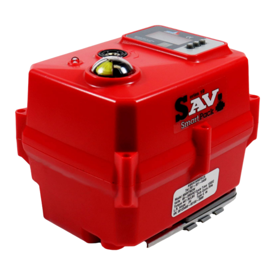
Series 19 SMART Modulating Failsafe Electric Actuator User
The Series 19 smart modulating electric actuator features a reversing motor with multi-
voltage capabilities, 95 VAC to 265 VAC (50/60 Hz) or 24 VAC/VDC, an OLED screen,
an internal heater, positioner, transmitter, alarm/fault contacts, a NEMA Type 4X
enclosure, manual override, visual beacon position indication, LED fault indicator (blue),
ISO mounting, and flying leads. The alarm/fault contacts are SPST and rated for 0.1
Amp @ 250 VAC/0.5 Amp @ 30 VDC, and are factory calibrated.
Cover removal is NOT required for installation and will void warranty!!
Additional options are NOT available for this model.
WARNING: Do not open actuator cover as warranty will be void!!
Model Number
S20C1C3HFSW
S50C1C3HFSW
S110C1C3HFSW
NOTE: Amp rating is considered running.
Duty cycles are for ambient temperature (73° F)
The Series 19 electric actuator has a sealed cable gland with 2 meter flying leads. The
electrician is required to make field connections as per the wiring schematic shown in
this manual for model numbers and voltages listed above. The electrician is responsible
for following all and any, local and/or agency wiring practices.
Note: Not all wires provided will be used.
Need more information? Download a complete IOM at our website.
File: Series 19 SMART Modulating Failsafe User Manual
Manual
Description
Electrical Requirement
95 VAC to 265
VAC
Torque
(in-lbs)
Amp
Duty
Draw
Cycle
177
0.18
75%
442
0.24
75%
973
0.90
75%
24 VAC/24
Cycle Time
VDC
per 90
Amp
Duty
Degrees
Draw
Cycle
(Seconds)
0.96
75%
10 seconds
1.20
75%
10 seconds
4.80
75%
10 seconds
www.asahi-america.com
Rev B
3/14/2022
Weight
(Pounds)
1.7
3.5
4.8
Page 1 of 5
Advertisement
Table of Contents
Troubleshooting

Related Manuals for ASAHI 19 Series

Summary of Contents for ASAHI 19 Series
- Page 1 Note: Not all wires provided will be used. Need more information? Download a complete IOM at our website. www.asahi-america.com File: Series 19 SMART Modulating Failsafe User Manual Rev B 3/14/2022...
- Page 2 If a different control signal/loop is required, then another unit with the specific control signal/loop must be used. Need more information? Download a complete IOM at our website. www.asahi-america.com File: Series 19 SMART Modulating Failsafe User Manual Rev B...
- Page 3 Size 50 – 110 can be calibrated for EITHER a voltage or a current control signal/loop via onboard firmware. Please contact the factory for instructions. Need more information? Download a complete IOM at our website. www.asahi-america.com File: Series 19 SMART Modulating Failsafe User Manual Rev B...
- Page 4 Loose/poor termination Confirm proper termination Need more information? Download a complete IOM at our website. www.asahi-america.com File: Series 19 SMART Modulating Failsafe User Manual Rev B 3/14/2022 Page 4 of 5...
- Page 5 4-20 mA actuator wiring, as an example) Series 19 ISO 5211 Output Series 19 Envelope Dimensions Need more information? Download a complete IOM at our website. www.asahi-america.com File: Series 19 SMART Modulating Failsafe User Manual Rev B 3/14/2022 Page 5 of 5...
Need help?
Do you have a question about the 19 Series and is the answer not in the manual?
Questions and answers