
Subscribe to Our Youtube Channel
Related Manuals for Arbor Technology ARES-1980 Series


Summary of Contents for Arbor Technology ARES-1980 Series
- Page 1 ARES-1980 Series Fanless Rugged Controller with 11 Gen. ® Intel Core™ i7/i5/i3 Processor User’s Manual Version 1.0 P/N: 4016198000100P 2021.12...
- Page 2 Revision History Version Date Description 2021.12 Initial release - II -...
-
Page 3: Table Of Contents
Contents Contents Revision History ................II Contents ....................i Preface....................iii Copyright Notice ..................iii Declaration of Conformity ...............iii CE ....................iii FCC Class A ..................iii RoHS ....................iv SVHC / REACH ................iv Important Safety Instructions ..............v Warning ....................vi Lithium Battery Replacement ..............vi Technical Support .................. -
Page 4: Contents
Contents Chapter 5 - BIOS ................39 5.1. Main ....................42 5.2. Advanced ..................43 5.2.1. CPU Configuration ............... 44 5.2.2. Power & Performance ............45 5.2.3. Trusted Computing ............. 48 5.2.4. ACPI Settings ............... 50 5.2.5. F81966 Super IO Configuration ........... 51 5.2.6. -
Page 5: Preface
Preface Copyright Notice All Rights Reserved. The information in this document is subject to change without prior notice in order to improve the reliability, design and function. It does not represent a commitment on the part of the manufacturer. Under no circumstances will the manufacturer be liable for any direct, indirect, special, incidental, or consequential damages arising from the use or inability to use the product or documentation, even if advised of the possibility of such damages. -
Page 6: Rohs
(PBDE) in electrical and electronic products. Member states of the EU are to enforce by 7/1/2006. ARBOR Technology Corp. hereby states that the listed products do not contain unintentional additions of lead, mercury, hex chrome, PBB or PBDB that exceed a maximum concentration value of 0.1% by weight or for cadmium exceed... -
Page 7: Important Safety Instructions
Preface Important Safety Instructions Read these safety instructions carefully 1. Read all cautions and warnings on the equipment. 2. Place this equipment on a reliable surface when installing. Dropping it or letting it fall may cause damage 3. Make sure the correct voltage is connected to the equipment. 4. -
Page 8: Warning
Preface Warning The Box PC and its components contain very delicately Integrated Circuits (IC). To protect the Box PC and its components against damage caused by static electricity, you should always follow the precautions below when handling it: 1. Disconnect your Box PC from the power source when you want to work on the inside. -
Page 9: Warranty
Preface Warranty This product is warranted to be in good working order for a period of one year from the date of purchase. Should this product fail to be in good working order at any time during this period, we will, at our option, replace or repair it at no additional charge except as set forth in the following terms. - Page 10 This page is intentionally left blank. - viii -...
-
Page 11: Chapter 1 - Introduction
Chapter 1 Introduction Chapter 1 - Introduction - 1 -... -
Page 12: Features
Introduction 1.1. Features • Onboard Intel® Core™ i Processor (Tiger Lake UP3) • Support 2 x 260-pin DDR4 SO-DIMM sockets • Support 5G (Sub-6G) module, M.2 NVMe SSD Gen3x4, USB 3.2 Gen2, and 2.5 GbE LAN • Rich I/O: 4 x COM/ 3 x LAN/ 4 x USB3.2 Gen 2/ Remote PWR •... -
Page 13: Specifications
Introduction 1.3. Specifications System ® Soldered onboard Intel i7/ i5/ i3 Processor (Default: i5 CPU Tiger Lake-U) 2 x 260-pin DDR4 SO-DIMM sockets, supporting 3200MHz SDRAM Memory up to 64GB Chipset ® ® Graphics Intel Iris Xe Graphics ® 2 x Intel i211AT PCIe controller LAN Chipset ®... - Page 14 Introduction Storage 1 x M.2 M-Key 2242/2280 (PCIe Gen III x4 + SATAIII) Type 1 x 2.5” HDD/SSD tray (SATA III + SATA PWR connector) Environmental -20 ~ 60°C (-4 ~ 140°F), ambient w/ air flow Operating Temp. Storage Temp. -40 ~ 70°C (-40 ~ 158°F) Operating 10-95% @ 60°C (non-condensing)
-
Page 15: Inside The Package
Introduction OS Support Windows 10 IoT Ubuntu 18.04 1.3. Inside the Package Upon opening the package, carefully inspect the contents. If any of the items is missing or appears damaged, contact your local dealer or distributor. The package should contain the following items: 1 x ARES-1980 Standard Accessories that contains the following items:... - Page 16 This page is intentionally left blank. - 6 -...
-
Page 17: Chapter 2 - Getting Started
Chapter 2 Getting Started Chapter 2 - Getting Started - 7 -... -
Page 18: Dimensions
Getting Started 2.1. Dimensions - 8 -... -
Page 19: Overview
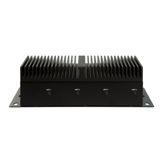
Getting Started 2.2. Overview 2.2.1. Front View Power Button/ RJ-45 ports RS232/422/485 Power LED 2.5 GbE LAN DB-9 connectors HDMI 2.0b USB 3.2 Gen 2 Reset Mic in Audio Out RJ-45 ports DisplayPort 1.4 RS232 GbE LAN DB-9 connectors (PoE) 2.2.2. -
Page 20: Right Side View
Getting Started 2.2.3. Right Side View DVI-D Ports DC-IN Multi-Serial Bus Remote On/Off Control - 10 -... -
Page 21: Driver Installation Note
Getting Started 2.3. Driver Installation Note For operating system of Windows 10, please go to our website at www.arbor-technology.com and download the driver pack from the product page. Then unzip the downloaded file and follow the sequence below to install the drivers to prevent errors: Chipset →... - Page 22 This page is intentionally left blank. - 12 -...
-
Page 23: Chapter 3 - Engine Of The Computer
Chapter 3 Engine of the Computer Chapter 3 - Engine of the Computer - 13 -... -
Page 24: Boards Overview
Engine of the Computer 3.1. Boards Overview The PCBs of the computer varies according to the models. The following table lists the PCBs of each model: (21) IO1 (22) PWRIN1 (20) JLS_PWR1 (1) PWF1 (19) MMkey1 (2) COM3 (3) COM2 (4) JCP1 (6) JV2 (5) JV1... - Page 25 Engine of the Computer Connectors Label Description (1) PWF1 Power button and Power LED Connector (2) COM3 COM port for 9pin D-SUB (3) COM2 COM port for 9pin D-SUB (4) JCP1 Power selection for COM port (5) JV1 COM1 function (6) JV2 COM2 function (7) CN2...
-
Page 26: Connectors
Engine of the Computer 3.2. Connectors (1) PWF1 Function: Power button and Power LED Connector Connector Type: 2.00 mm pitch 1x4-pin one-wall connector Pin Assignment: Pin Desc. PWR_IN_SW# LED+ (2)(3) COM2/3 (COM3/4 on front panel) Function: RS232 DB9 connector Connector Type: 2.00 mm pitch 2x5 pin box header Pin Assignment: Pin Desc. - Page 27 Engine of the Computer (4)JCP1 Function: Power selection for COM port Jumper Type: Onboard 2.00mm-pitch 1x3-pin header Setting: Description Short 1-2 COM_5V Short 2-3 COM_12V (5)(6)JV1/JV2 Function: RI/5V/12V (Pin 9) Selection for COM Port Jumper Type: Onboard 2.00mm-pitch 1x3-pin header Setting: Description Short 1-2...
- Page 28 Engine of the Computer (9) MC2 Function: PCI Express Mini-card Full socked Connector Type: Onboard 0.8mm pitch 52-pin edge card connector. Pin Assignment: (10) MEKEY1 Function: M.2 E-Key socket (w/ CNVi+USB2.0) for optional Wi-Fi/BT Connector Type: M.2 E-Key 2230 Socket Pin Assignment: The pin assignments conform to the industry standard.
- Page 29 Engine of the Computer (13) JBAT2 Function: Clears/keeps CMOS Jumper Type: 2.00 mm pitch 1x2-pin header Setting: Description Short Clears CMOS Open Keeps CMOS (default) (14) SIM1 Function: SIM Card Socket Connector Type: 6-pin SIM card socket Pin Assignment: Pin Desc. Pin Desc C2 RST C5 GND...
- Page 30 Engine of the Computer (17) SIM3 Function: SIM Card Socket Connector Type: 6-pin SIM card socket Pin Assignment: Pin Desc. Pin Desc C2 RST C5 GND C7 I/O (18) DGP1 Function: Debug port Connector Type: 2.00mm-pitch 2x5-pin header Pin Assignment: Pin Description Description 24MHz Clock...
- Page 31 Engine of the Computer (20)JLS_PWR1 Function: Multi Serial Bus power connector Jumper Type: Onboard 2.00mm-pitch 1x3-pin header Setting: Description Short 1-2 5V(default) Short 2-3 3.3V (21) IO1 Function: Multi Serial Bus connector Connector Type: 2.00mm-pitch 2x6-pin header Pin Assignment: Pin Description Description I2C0_SCL I2C0_SDA...
- Page 32 This page is intentionally left blank. - 22 -...
-
Page 33: Chapter 4 - Installation And Maintenance
Chapter 4 Installation & Maintenance Chapter 4 - Installation and Maintenance - 23 -... -
Page 34: Disassembling And Assembling The Computer
Installation & Maintenance 4.1. Disassembling and Assembling the Computer 4.1.1. Disassembling the Computer To use onboard jumpers/connectors or to install/remove internal components, you will need to open the computer to access the inside of the computer. Follow through the guide below to disassembly the computer. 1. -
Page 35: Assembling The Computer
Installation & Maintenance 4.1.2. Assembling the Computer After completing the required hardware installation and jumpers settings, assemble the computer by performing the proceeding steps in reverse order. - 25 -... -
Page 36: Installing Hardware
Installation & Maintenance 4.2. Installing Hardware 4.2.1. Installing Memory Module The computer has two 260-pin DDR4 SO-DIMM sockets that each socket support up to 32 GB maximum system memory. To install a memory module: 1. Open the ARES-1980's case and locate memory module sockets. 2. - Page 37 Installation & Maintenance 3. Slide the module into place. Once the memory module is fully inserted into the socket, press down on the top edge of the device to latch it into place. 4. This way it’s flat to the laptop’s bottom. The carrier should snap into place with latches.
-
Page 38: Installing/Replacing A Ssd Or Hdd
Installation & Maintenance 4.2.2. Installing/Replacing a SSD or HDD 1. Remove the hard drive bay from the bottom side chassis by loosening the 4 screws. 2. Slide the 2.5” HDD or SSD storage device into the drive bay and ensure it connects to the SATA connector. - Page 39 Installation & Maintenance 4. Connect the SATA interface and power cables to the SATA & power connectors on the main board. 5. Secure the drive bay back to the bottom side chassis by fastening the 4 screws you removed in Step 1. - 29 -...
-
Page 40: Installing M.2 Module
Installation & Maintenance 4.2.3. Installing M.2 Module The computer has a M.2 M-Key socket for NvME SSD storage. This section will use a 22 x 80 form factor as the installation example. 1. Remove the bottom cover from the computer as described in 4.1.1. -
Page 41: Installing Encription Dongle
Installation & Maintenance 4.2.4. Installing Encription Dongle The computer has a USB 2.0 connector on the main board for the users who need additional secured encryption key installed. If an encryption dongle requirement was needed, user can use this USB connector inside the computer. Note: The USB dimension need to be 19mm to 30mm. -
Page 42: Install/Uninstall Sim Card And Relative Connection Module
Installation & Maintenance 4.2.5. Install/uninstall SIM Card and relative connection module This section will guide you how to install SIM card and relative connection module. 1. Remove the bottom cover from the computer as described in 4.1.1. Disassembling the Computer on page 2. - Page 43 Installation & Maintenance 5. Close the SIM card holder door and slide the door to the LOCK edge to lock into place. 6. Locate the MC1 slot and insert the relative communication module then fasten the screw. - 33 -...
- Page 44 Installation & Maintenance 7. If the other SIM card is needed, please follow the steps above and install the SIM card in the second or third position as the picture. 8. Locate the MBKEY slot and insert the relative communication module then fasten the screw.
-
Page 45: Install/Uninstall Wi-Fi Connection Module
Installation & Maintenance 4.2.6. Install/uninstall WI-FI connection module 1. Remove the bottom cover from the computer as described in 4.1.1. Disassembling the Computer on page 2. Locate the M.2 E-Key socket for wireless module. 3. Prepare the Wi-Fi module kit. The module is a M.2 E-Key socket form factor, with two MHF connectors, one is “MAIN“, and the other is “AUX“. - Page 46 Installation & Maintenance 5. Connect the RF antenna’s MHF connector to the Wi-Fi module’s main connector marked 0. If you are going to connect a secondary antenna, connect it to the connector marked Connect the RF antenna’s MHF connector to the Wi-Fi module’s main connector (marked 2) Connect the secondary RF...
- Page 47 Installation & Maintenance 8. From the other end of the RF antenna, which is an SMA connector, remove the washer and the nut. Note the SMA connector has the form of a threaded bolt, with one flat side. Among the screw Remove thread, there is a the nut and...
- Page 48 Installation & Maintenance 10. Mount the washer first and then the nut to the SMA connector. Make sure the nut is tightened. Mount the washer and the nut to the SMA connector. Tighten the nut. 11. After completing the required hardware installation, assemble the computer by performing the proceeding steps in reverse order.
-
Page 49: Chapter 5 - Bios
Chapter 5 BIOS Chapter 5 - BIOS - 39 -... - Page 50 BIOS The BIOS Setup utility is featured by American Megatrends Inc to configure the system settings stored in the system’s BIOS ROM. The BIOS is activated once the computer powers on. When the computer is off, the battery on the main board supplies power to BIOS RAM.
- Page 51 BIOS Key Commands The BIOS Setup utility relies on a keyboard to receive user’s instructions. Hit the following keys to navigate within the utility and use the utility. Keystroke Function ← → Moves left/right between the top menus. ↓ ↑ Moves up/down between highlight items.
-
Page 52: Main
BIOS 5.1. Main The Main menu features the settings of System Date and System Time and displays some BIOS info. Note: Actual model name and board information varies according to your model. Setting Description Project Version Delivers the model name of the computer and BIOS version. Build Date and Time Delivers the date and time when the BIOS Setup utility was made/ updated. -
Page 53: Advanced
BIOS 5.2. Advanced Setting Description CPU Configuration 5.2.1. CPU Configuration on page Power & Performance 5.2.2. Power & Performance on page Trusted Computing 5.2.3. Trusted Computing on page ACPI Settings 5.2.4. ACPI Settings on page F81966 Super IO Configuration 5.2.5. F81966 Super IO Configuration on page Hardware Monitor 5.2.6. -
Page 54: Cpu Configuration
BIOS 5.2.1. CPU Configuration Setting Description When enabled, a VMM can utilize the additional hardware Intel (VMX) Virtualization capabilities provided by Vanderpool Technology Technology ► Options: Enabled (default) or Disabled Number of cores to enable in each processor package. Active Processor Cores ►... -
Page 55: Power & Performance
BIOS 5.2.2. Power & Performance Setting Description Configure CPU Power Management CPU - Power Management Control 5.2.2.1 CPU Power & Performance on page Configure graphics processors Power Management GT - Power Management Control 5.2.2.2 GT Power & Performance on page - 45 -... - Page 56 BIOS 5.2.2.1 CPU Power & Performance Setting Description Set the performance state that the BIOS will set before the OS handoff. Boot performance Mode ► Options: Max Non-Turbo Performance (default), Max Battery and Turbo Performance Intel (R) Speed Step (tm) Enable (default) / Disable Intel SpeedStep Config TDP Configurations Configurable TDP Mode C States...
- Page 57 BIOS 5.2.2.2 GT Power & Performance Setting Description Function of activation and deactivation the energy-saving mechanism integrated into the Intel graphics core processors RC6 (Render Standby) when the computer enters sleep mode. Enable (default) / Disable This item maximum GT frequency limited by te user. Value beyond the range will be clipped to min/max supported by SKU.
-
Page 58: Trusted Computing
BIOS 5.2.3. Trusted Computing Setting Description This item enables or disables BIOS support for security device. O.S will not show Security Device. Security Device Support Enabled (Default) / Disabled This item enables or disables SHA-1 PCR Bank. SHA-1 PCR Bank Enabled/Disabled(Default) Enables or disables SHA-1 PCR Bank. - Page 59 BIOS Enables or disables Endorsement Hierarchy. Endorsement Hierarchy Enabled (Default) / Disabled Allows user to select the TCG2 Spec Version Support. TCG_1_2: Compatible mode for Win8/ Win10 TPM2.0 UEFI Spec Version TCG_2: Support new TCG2 protocol and event for Win10 or later.
-
Page 60: Acpi Settings
BIOS 5.2.4. ACPI Settings Setting Description Enable ACPI Auto Enable (default) or Disable BIOS ACPI Auto Configuration Configuration Only available when BIOS ACPI Auto Configuration is enabled. Select ACPI sleep state the system will enter when the ACPI Sleep State SUSPEND button is pressed. -
Page 61: F81966 Super Io Configuration
BIOS 5.2.5. F81966 Super IO Configuration Note: The quantity of serial ports varies according to your model. Setting Description To configure each COM port settings. Serial Port 1/2/3/4 Configuration Note: The quantity of serial ports varies according to your model. Serial Port Enable (default) or Disable the Serial Port (COM). -
Page 62: Hardware Monitor
BIOS 5.2.6. Hardware Monitor Access this submenu to monitor the hardware status. - 52 -... -
Page 63: S5 Rtc Wake Settings
BIOS 5.2.7. S5 RTC Wake Settings Setting Description Enable or Disable (default) system wake on alarm event. ► Options available are: Wake System Disabled (default): Fixed Time: System will wake on the hr::min::sec specified. from S5 DynamicTime: If selected, you need to set Wake up minute increase from 1 - 5. -
Page 64: Serial Port Console Redirection
BIOS 5.2.8. Serial Port Console Redirection Setting Description Allow you to enable or disable the console redirection feature. Serial Port Console Redirection Enabled / Disabled (Default) Legacy Console Allow you to select a COM part to display redirection of Legacy OS Redirection Settings and Legacy OPRom Messages. -
Page 65: Usb Configuration
BIOS 5.2.9. USB Configuration Setting Description Enables/disables legacy USB support. ► Options available are Enabled (default), Disabled and Auto. ► Select Auto to disable legacy support if no USB device are Legacy USB Support connected. ► Select Disabled to keep USB devices available only for EFI applications. - Page 66 BIOS Use this item to set the time-out value for control, bulk, and interrupt USB transfer time- transfers. ► Options: 1 sec, 5 sec, 10 sec, 20 sec (default) Use this item to set USB mass storage device start unit command time- Device reset time- out.
-
Page 67: Network Stack Configuration
BIOS 5.2.10. Network Stack Configuration Setting Description Network Stack Enable or Disable (default) UEFI network stack. - 57 -... -
Page 68: Nvme Configuration
BIOS 5.2.11. NVME Configuration Access this submenu to view the NVMe controller and driver information. - 58 -... -
Page 69: Chipset
BIOS 5.3. Chipset Submenu Description System Agent (SA) Configuration See 5.3.1. System Agent (SA) Configuration on page PCH-IO Configuration 5.3.2. PCH-IO Configuration on page - 59 -... -
Page 70: System Agent (Sa) Configuration
BIOS 5.3.1. System Agent (SA) Configuration Submenu Description System Agent (SA) Configuration Memory Configuration 5.3.1.1. Memory Configuration on page Graphics Configuration 5.3.1.2. Graphics Configuration on page VT-d Enable (default) or Disable VT-d function - 60 -... - Page 71 BIOS 5.3.1.1. Memory Configuration Access this submenu to view the memory configuration. - 61 -...
- Page 72 BIOS 5.3.1.2. Graphics Configuration Note: This page varies according to your model. Setting Description Select the Aperture Size Aperture Size ► Options: 128MB, 256MB (default), 512MB and 1024MB. Select the DVMT 5.0 Pre-allocated (Fixed) Graphic Memory size used by the Internal Graphic Device. DVMT Pre-Allocated ►...
-
Page 73: Pch-Io Configuration
BIOS 5.3.2. PCH-IO Configuration Setting Description PCI Express Configuration 5.3.2.1. PCI Express Configuration on page SATA And RST Configuration 5.3.2.2. SATA And RST Configuration on page Specify what state to go to when power is re-applied after a power failure (G3 state). Power on after power fail ►... - Page 74 BIOS 5.3.2.1. PCI Express Configuration Setting Description M.2 B-key PCI Express root port setings. Control the M.2 B-key root port. Intel LAN I225LM PCI Express root port setings. Control the LAN I225LM root port. Intel LAN I211 PCI Express root port setings. Control the LAN I211 root port. Disable or set the ASPM level.
- Page 75 BIOS 5.3.2.2. SATA And RST Configuration Setting Description Enables (default) / disables SATA device(s). SATA Controller(s) Enables (default) / disables PCH to aggressively enter link Aggressive LPM Support power state. Configures how SATA controller(s) operate. ► SATA Mode Selection Options: AHCI (default) and Intel RST premium With Intel Optane System Acceleration.
-
Page 76: Security
BIOS 5.4. Security Setting Description To set up an administrator password: Select Administrator Password. Administrator An Create New Password dialog then pops up onscreen. Password Enter your desired password that is no less than 3 characters and no more than 20 characters. Hit [Enter] key to submit. -
Page 77: Security Boot
BIOS 5.4.1 Security Boot Setting Description Enable/Disable (default) secure boot. Secure Boot Allow users to set the secure boot selector. Secure Boot Mode Standard/Custome (default) mode. Restore Factory Force system to restore default secure boot key database. Keys Reset to Setup Delete all secure boot key databases. -
Page 78: Boot
BIOS 5.5. Boot Setting Description Set how long to wait for the prompt to show for entering BIOS Setup. Setup Prompt Timeout ► The default setting is 2 (sec). ► Set it to 65535 to wait indefinitely. Sets whether to enable or disable the keyboard’s NumLock state when the system starts up. - Page 79 BIOS Power Delay Function Set the system support power delay function. ► Options: Enable (default): Support power delay function. Disable: Power on/off manually operated. Power on delay Power Delay Function Select the time which the system will power on. ► Options: Manually Operator (default), 04 Seconds, 08 Seconds and 16 Seconds.
-
Page 80: Save & Exit
BIOS 5.6. Save & Exit Setting Description Save Changes Saves the changes and quits the BIOS Setup utility. and Exit Restores all settings to defaults. Restore Defaults ► This is a command to launch an action from the BIOS Setup utility. Boot Override presents a list in context with the boot devices in the system. - Page 81 Appendix Appendix - 71 -...
- Page 82 Appendix Appendix A. 16-bit DIO Signal Connections A.1. Isolated Digital Input Connections The input (IN-C) will accept supply voltages. Make sure the Von (IN-C to IN) is more than 12V and Voff (IN-C to IN) is less than 5V. The following diagram shows the connection between outside signal and the system.
- Page 83 Appendix A.2. Isolated Digital Output Connections When an isolated output channel is being used as an output channel, if an external voltage is applied, the current will flow from the external voltage source to the system. Make sure that the current through each out pin does not exceed 100 mA.
Need help?
Do you have a question about the ARES-1980 Series and is the answer not in the manual?
Questions and answers