Table of Contents
Advertisement
Quick Links
Advertisement
Table of Contents

Related Manuals for Foerster CIRCOGRAPH DS


Summary of Contents for Foerster CIRCOGRAPH DS
- Page 1 ® CIRCOGRAPH Sensor system Ro 130 6.453 Operating Instructions...
- Page 3 SENSORSYSTEM Ro 130 FOREWORD These operating instructions were written to be read, understood and complied with in full by those persons responsible for operating the ma- chine. The complete operating instructions consist of the following sections: 1 Safety 2 Description 3 Installation 4 Operation 5 Maintenance...
- Page 4 Copyright 2006 Institut Dr. Foerster for Documentation: INSTITUT DR. FOERSTER GMBH & CO KG retains ownership of all property rights to all information provided in this document. The docu- ments shall support only operation and service of the delivered units. All (direct and indirect) duplication and disclosure to unauthorized third par- ties is strictly prohibited.
-
Page 5: Table Of Contents
SENSORSYSTEM Ro 130 CONTENTS SAFETY ........................1-1 Dangers posed by this machine ...................1-1 Safety information and tips...................1-1 Use as intended ......................1-2 Dangers posed by accessories ..................1-2 Emissions ........................1-2 Danger sources ......................1-3 Workstations.........................1-3 Authorised operators ....................1-3 Personal safety equipment...................1-4 1.10 Safety measures at the installation location ..............1-4 1.11 Protective safety devices .....................1-4 1.12 Behaviour in the event of an emergency..............1-4 1.13 Declaration of conformity .....................1-5... - Page 6 SENSORSYSTEM Ro 130 CONTENTS INSTALLATION......................3-1 Setup and Connection....................3-1 OPERATION......................4-1 Dimension change .......................4-1 Selection and installation of the protective nozzles............4-2 4.2.1 Selection of the protective nozzles ..............4-2 4.2.2 Required tools ....................4-3 Changing nominal diameter ..................4-4 4.3.1 Preparation .......................4-4 Remove Entry Nozzle..................4-5 4.3.2 4.3.3 Adjusting nominal diameter ................4-7...
- Page 7 SENSORSYSTEM Ro 130 CONTENTS MAINTENANCE ....................... 5-1 Maintenance schedule ....................5-1 Cleaning ........................5-2 Removing and fitting the test heads ................5-2 Replacing parts subject to wear ..................5-5 Maintenance of the roller guides ..................5-6 Lubrication ......................5-6 5.5.1 5.5.2 Replacing the track rollers ................5-7 5.5.3 Removing the roller guide levers ..............5-8 Checking and changing the cone belt ................5-9...
- Page 8 SENSORSYSTEM Ro 130 CONTENTS Notes: 6.453 – 01/2006...
-
Page 9: Safety
SENSORSYSTEM Ro 130 SAFETY 1.1 Dangers posed by this machine 1 SAFETY 1.1 Dangers posed by this machine The sensor system features protective safety devices. It has been sub- jected to a safety test and safety acceptance test. In the event of operat- ing errors or misuse, the machine may pose dangers and risks to the life and limb of the operator, the machine and other operator’s valuables and... -
Page 10: Use As Intended
SENSORSYSTEM Ro 130 1.3 Use as intended SAFETY 1.3 Use as intended The sensor system is suitable only for non-destructive testing of round material. Diameter range: refer to Technical Data Smaller diameters and larger diameters may not be admitted into the sensor system under any circumstances. -
Page 11: Danger Sources
SENSORSYSTEM Ro 130 SAFETY 1.6 Danger sources 1.6 Danger sources The sensor system operates with a rotating test system and an attached roller guide system during operation. A person coming into contact with the roller guide or the rotating test system may suffer very serious injuries. Switch off the drives before you put your hands into or touch the sensor system. -
Page 12: Personal Safety Equipment
SENSORSYSTEM Ro 130 1.9 Personal safety equipment SAFETY 1.9 Personal safety equipment You are to wear ear plugs, if the A-weighted equivalent sound pressure level at the workstations of the sensor system is greater than 85 dB(A). Sound pressure level for this equipment: refer to 2.4 Technical Data 1.10 Safety measures at the installation location The sensor system must be installed stably on a machine foundation pro- vided for it and must be firmly anchored to the foundation. -
Page 13: Declaration Of Conformity
European Standards EN 12100, EN 60204 European Directive 73/23/EEC: Safety of electrical apparatus European Standard EN 61010 European Directive 89/336/EEC: Electromagnetic Compatibility European Standard EN 61326-1 February 23, 2005 INSTITUT DR. FOERSTER Division TS - Test Systems Dr. Jürgen Schröder 6.453 – 01/2006... - Page 14 SENSORSYSTEM Ro 130 Notes: 6.453 – 01/2006...
-
Page 15: Description
SENSORSYSTEM Ro 130 DESCRIPTION 2.1 Application 2 DESCRIPTION 2.1 Application Non-destructive testing of ferromagnetic, austenitic and non- ferromagnetic round materials (wires, bars, and tubes) for surface flaws in ® conjunction with the CIRCOGRAPH DS testing and evaluation electronic equipment and a suitable mechanical handling system. Diameter range of testing material 10 to 130 mm Preferably piece testing Surface free of scale, wherever possible bright... -
Page 16: Mode Of Operation
SENSORSYSTEM Ro 130 2.2 Mode of operation DESCRIPTION 2.2 Mode of operation The sensor system operates on the basis of the eddy current principle in accordance with EN 12084. Rotating systems are used to detect longitu- dinal surface defects. Probes rotate at high speed and without physical contact around the test piece. -
Page 17: Construction
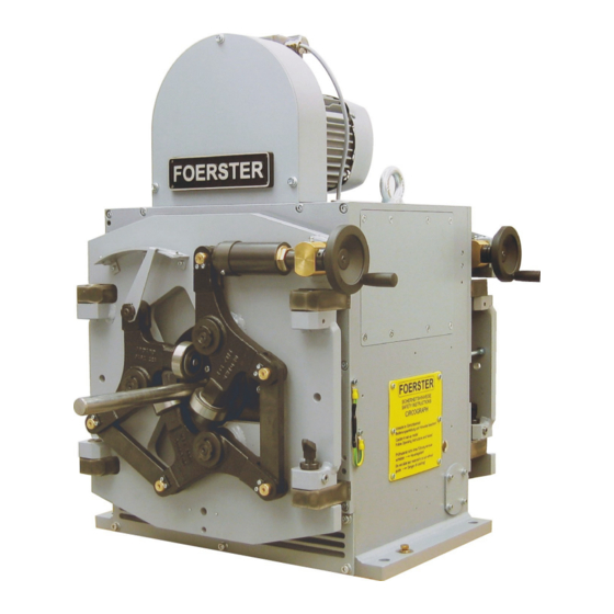
Fig. 2.1 Test equipment configuration, top: CIRCOGRAPH DS / MOC SB, bottom: Rotating head Ro 130 entry and exit side CIRCOGRAPH DS test electronics and the connection cables are re- quired for a complete test system, besides the sensor system which scans the test material and generates the eddy-current signal. - Page 18 SENSORSYSTEM Ro 130 2.3 Construction DESCRIPTION Fig. 2.2 CIRCOGRAPH Sensor system Ro 130, main view, legend see Chap. 2.7 Roller guide Clamping ring - Nozzle - Adapter - Flange Nozzle - Nozzle holder - Inner and Outer sleeve Roller guide Flaw direction Fig.
- Page 19 SENSORSYSTEM Ro 130 DESCRIPTION 2.3 Construction In order to withstand the rough conditions of use, the Ro 130 has been designed to be dust-protected, robust and reliable by means of complex constructional measures such as labyrinth seals and dirt deflectors. The chamber surrounding the test zone serves the purpose of contact and burst protection as well as dust collection.
-
Page 20: Test Heads
SENSORSYSTEM Ro 130 2.3 Construction DESCRIPTION 2.3.1 Test Heads The test heads are both the heart of the sensor system and its most criti- cal components. They consist of an eddy-current probe with field, measuring and clear- ance windings which are installed in a precise mechanical holder and are connected by means of a highly flexible special cable with a connection plug. -
Page 21: Rotating Head Ro 130
SENSORSYSTEM Ro 130 DESCRIPTION 2.3 Construction 2.3.2 Rotating Head Ro 130 The rotating head is the main component of the sensor system. It consists of: rotor transmitter drive housing rotating head electronics The operator front is to be selected as right or left in the order! Fig. - Page 22 SENSORSYSTEM Ro 130 2.3 Construction DESCRIPTION Transmitter Wear-resistant rotating transmitter in disc-type construction with two field transmitter, four measuring channels and a clearance channel. Consisting of a rotor and stator, it transmits the field current for the rotat- ing probes from the stator to the rotor and, in the opposite direction, transmits the test signal to the test electronics for evaluation.
- Page 23 SENSORSYSTEM Ro 130 DESCRIPTION 2.3 Construction Drive Indestructible 3-phase drive with a cage motor in conformance with stan- dards. External motor control for power supply to the drive. MOC SB motor control rotational speed switchable 1,500 or 3,000 rpm, with electrical breaking minimized bearing wear through adaptation of rotational speed to test- ing speed for applications with changing testing speeds...
- Page 24 SENSORSYSTEM Ro 130 2.3 Construction DESCRIPTION Diameter adjustment Diameter adjustment is carried out manually with a socket spanner. The linear scale is located on the rotor. The scale division of 0.5 mm guaran- tees an accurate diameter setting. Protective nozzles The protective nozzles have a dual function: They protect the test heads from damage, particularly during entry and exit of the test material, provided that the straightness conditions and the...
- Page 25 2.3 Construction Entry and exit nozzles must always be used in pairs with the same nomi- nal value. Protective nozzles can be ordered from INSTITUT DR. FOERSTER or can be manufactured by the customer on the basis of drawings. WARNING! Operation without protective nozzles is not permitted for damage and safety reasons.
- Page 26 SENSORSYSTEM Ro 130 2.3 Construction DESCRIPTION Roller guide The centric roller guides have two advantages: The centric triple roller guides have two advantages: In set-up mode, a calibration piece with reference flaws can be held cen- trically outside the test line and the test electronics can be adjusted sim- ply, since the rotating probes periodically scan the test flaw and display the signal quasi-statically.
-
Page 27: Technical Data
SENSORSYSTEM Ro 130 DESCRIPTION 2.4 Technical Data 2.4 Technical Data Diameter range test material continuously adjustable 10 to 130 mm Revolution speed 1,500 or 3,000 rpm MOC SB motor control Switchable with Brake Deceleration times from 3,000 rpm without braking approx. -
Page 28: Dimension Sheet
SENSORSYSTEM Ro 130 2.5 Dimension sheet DESCRIPTION 2.5 Dimension sheet Entry side Fig. 2.9 Dimension sheet 1 2-14 6.453 – 01/2006... - Page 29 SENSORSYSTEM Ro 130 DESCRIPTION 2.5 Dimension sheet Fig. 2.10 Dimension sheet 2 2-15 6.453 – 01/2006...
-
Page 30: Operating, Storage And Transport Conditions
SENSORSYSTEM Ro 130 2.6 Operating, storage and transport conditions DESCRIPTION 2.6 Operating, storage and transport conditions Operation Temperature range test head +5° C to +80° C rotating system +5° C to +45° C Relative humidity test head 95 %, casually condensation permissible rotating system 85 %, condensation not permissible Degree of protection... -
Page 31: Standard Components
SENSORSYSTEM Ro 130 DESCRIPTION 2.7 Standard Components 2.7 Standard Components Legend No Part name Part-No Order-No. Rotating head Ro 130 6.453.01-1301 1656686 Testing cable DS 10M, CIRCOGRAPH-DS 6.460.01-9921 1650785 Motor cable 10M 6.460.01-9931 1638343 Grounding cable 10M 6.460.01-9911 1588818 Test head N, BS = 2 x 2.5 6.453.01.2311 1480766 Test head N, BS = 2 x 5... - Page 32 SENSORSYSTEM Ro 130 2.7 Standard Components DESCRIPTION Notes: 2-18 6.453 – 01/2006...
-
Page 33: Installation
SENSORSYSTEM Ro 130 INSTALLATION 3.1 Setup and Connection 3 INSTALLATION 3.1 Setup and Connection NOTE! The sensor system must be mounted on a horizontally shiftable lifting table in order to be able to change the dimensions or to carry out serv- ice work outside of the test line. - Page 34 6.460.01-9931 Testing cable l 10 m 6.460.01-9921 Test electronics Fig. 3.3 Connection 4-channel rotating head to CIRCOGRAPH DS NOTE! Protective conductor connection (PE) according to EN 61010 (VDE 0411) Connect the protective conductor terminal of the electronic cabinet and the other system components, e. g. control cabinets, motor control, ro-...
-
Page 35: Operation
SENSORSYSTEM Ro 130 OPERATION 4.1 Dimension change 4 OPERATION 4.1 Dimension change The following steps must be carried out during conversion I Set test head to new nominal value of testing material II Insert suitable protective nozzles III Set roller guides to test diameter IV Center sensor system in the test line Preparation Select protective nozzles for new test piece measurement... -
Page 36: Selection And Installation Of The Protective Nozzles
SENSORSYSTEM Ro 130 4.2 Selection and installation of the protective nozzles OPERATION 4.2 Selection and installation of the protective nozzles 4.2.1 Selection of the protective nozzles Function of the protective nozzles guarantee protection from damage during entry, even for test pieces with larger diameters, impermissible curvatures or deformed fronts or ends in addition during operation without roller guides: guide the test material... -
Page 37: Required Tools
SENSORSYSTEM Ro 130 OPERATION 4.2 Selection and installation of the protective nozzles 4.2.2 Required tools Usage Tool Order-No. Nozzle exchange and Hexagon screwdriver, warped 012 558 0 diameter setting a/f -2.5 mm (extend.) Hexagon screwdriver, warped 012 559 8 a/f -3 mm (extend.) Hexagon screwdriver, warped 012 560 1 a/f -4 mm (extend.) -
Page 38: Changing Nominal Diameter
SENSORSYSTEM Ro 130 4.3 Changing nominal diameter OPERATION 4.3 Changing nominal diameter 4.3.1 Preparation Select protective nozzles according to Chapter 4.2 Switch off drive and wait for standstill Move test material out of the sensor system Move sensor system out of the test line Opening the roller guides Turn the locking bolt in ccw direction up to the stop Swivel out the roller guide... -
Page 39: Remove Entry Nozzle
SENSORSYSTEM Ro 130 OPERATION 4.3 Changing nominal diameter 4.3.2 Remove Entry Nozzle Allen screws (B) Allen screws (A) Fig. 4.2 Changing the entry nozzles, legend see Chap. 2.7 Nozzle 10 - 30 mm Untighten three allen screws M 6x22 DIN 912 (A) Open and remove the clamping ring (11.2) Remove the nozzle (12) from the adapter (13), clamping ring (10) remains locked... - Page 40 SENSORSYSTEM Ro 130 4.3 Changing nominal diameter OPERATION Nozzle 31 - 68 mm Untighten three allen screws M 6x22 DIN 912 (A) Open and remove the clamping ring (11.1) Remove the nozzle (8) from the adapter (7), clamping ring (10) remains locked Change diameter range 31 - 68 >>...
-
Page 41: Adjusting Nominal Diameter
SENSORSYSTEM Ro 130 OPERATION 4.3 Changing nominal diameter 4.3.3 Adjusting nominal diameter Housing flange Unscrew three allen screws M 6x10 DIN 912 (C) Turn ccw and remove housing flange Allen screws (C) Fig. 4.4 Housing flange Note! Mass housing flange approx. 17 kg! 6.453 –... - Page 42 SENSORSYSTEM Ro 130 4.3 Changing nominal diameter OPERATION Recommended settings bright material raw from rolling track width Recommended test heads see in Fe - Nfe - Aust the opposite table. The diameter adjustment on the scale should be 6.453.01-2311 6.453.03-2311 2 x 2.5 mm according to the selected nozzle.
- Page 43 SENSORSYSTEM Ro 130 OPERATION 4.3 Changing nominal diameter Diameter setting WARNING! Never adjust the scale diameter to values higher than 132 mm! Overwinding can snap off the test heads from the cam disk and test heads will be clamped when reverse winding! Relax two clamping screws (D), approx.
-
Page 44: Remove Exit Nozzles
SENSORSYSTEM Ro 130 4.3 Changing nominal diameter OPERATION 4.3.4 Remove exit nozzles Allen screws ( (G) Allen screws ( (F) Allen screws ( (E) Fig. 4.7 Nozzle changing exit side, legend see Chap. 2.7 Nozzle 10 - 30 mm Note! Outer sleeve (16.2) remains fitted! Untighten three allen screws M 6x25 DIN 912 (E) Remove inner sleeve (16.1) with exit nozzle fitted (17) from outer... - Page 45 SENSORSYSTEM Ro 130 OPERATION 4.3 Changing nominal diameter Change diameter range 10 - 30 >> << 31 - 68 mm Untighten three allen screws M 8x20 DIN 912 (F) Remove / insert nozzle holder exit (16) Remove / insert adapter (14.1) Insert and tighten clamping ring (2) Nozzle 31 - 68 mm Note!
-
Page 46: Fitting Protective Nozzles
SENSORSYSTEM Ro 130 4.3 Changing nominal diameter OPERATION 4.3.5 Fitting protective nozzles Select nozzles according to Chap. 4.2.1 Note! Clean all parts before fitting them carefully! Check for wear each time before using them! Do not use worn nozzles Fig. 4.8 Fitting nozzles entry side, legend see Chap.2.7 WARNING! Adjust the test heads to the nominal diameter of the protective nozzles... - Page 47 SENSORSYSTEM Ro 130 OPERATION 4.3 Changing nominal diameter NOTE! Use only nozzle pairs with the same nominal diameter! Entry nozzle 10 - 30 mm Fit the entry nozzle (12) into the inserted adapter (13) by turning it The clamping ring (10) remains closed Fit the clamping ring entry (11.2) onto the adapter ring (13) and clamp it Tighten three allen screws M 6x22 DIN 912 (A) with 6 Nm Entry nozzle 31 - 68 mm...
- Page 48 SENSORSYSTEM Ro 130 4.3 Changing nominal diameter OPERATION Exit nozzle 69 - 135 mm Note! The adapter (14.1) is not in place Fit the exit nozzle (3) into the faceplate by turning it and fit the clamping ring exit (2) Tighten four allen screws M 8x20 DIN 912 (F) with 12 Nm Fig.
-
Page 49: Setting The Roller Guides
SENSORSYSTEM Ro 130 OPERATION 4.3 Changing nominal diameter 4.3.6 Setting the roller guides Set the roller guide coarsely to the nominal diameter in accordance with the scale (in the case of new track rollers, the clear diameter of the track rollers corresponds exactly to the scale setting) Fig. -
Page 50: Rotational Speed Preselection
SENSORSYSTEM Ro 130 4.4 Rotational speed preselection OPERATION 4.4 Rotational speed preselection MOC SB motor control Rotational speed switchable 1,500 or 3,000 rpm The motor control supplies the required voltages and currents and contain the necessary switching and safety devices (contactors, motor protection switches, protective circuits). -
Page 51: Switching On Motor
SENSORSYSTEM Ro 130 OPERATION 4.5 Switching on motor 4.5 Switching on motor NOTE! Check the diameter and height settings of the sensor system before switching on. The operating elements used to switch on the rotating head drive are lo- cated on the motor control. The motor control is installed in a separate housing. - Page 52 SENSORSYSTEM Ro 130 4.5 Switching on motor OPERATION Notes: 4-18 6.453 – 01/2006...
-
Page 53: Maintenance
SENSORSYSTEM Ro 130 MAINTENANCE 5.1 Maintenance schedule 5 MAINTENANCE 5.1 Maintenance schedule WARNING: Always switch off the drive and wait for the machine to stop before per- forming work of any kind! Do not touch or tamper with the sensor system, with the rotating unit operating! Deceleration times: without braking approx. -
Page 54: Cleaning
SENSORSYSTEM Ro 130 5.2 Cleaning MAINTENANCE 5.2 Cleaning WARNING! Do not use cold cleaner! Isopropyl alcohol or denatured ethyl alcohol are recommended as cleaning agents. Take care of directions of use given by the producer of cleansing agent! Make sure the areas around the rotating parts are clean! Remove abrasion and dirt with an industrial vacuum cleaner Clean rotating disc and test heads with alcohol Clean test piece sensor (external) with a soft cloth... -
Page 55: Removing And Fitting The Test Heads
SENSORSYSTEM Ro 130 MAINTENANCE 5.3 Removing and fitting the test heads 5.3 Removing and fitting the test heads NOTE! Make sure the plug contacts are clean! Open housing flange Untighten three allen screws M 8x16 DIN 912 (C) Turn and remove housing flange Fig. - Page 56 SENSORSYSTEM Ro 130 5.3 Removing and fitting the test heads MAINTENANCE WARNING! Use test heads as a set with the same specifications. The type number is found on the side of the test heads. Clean all parts, especially the connection pin (2), the flange bushings (ref.
-
Page 57: Replacing Parts Subject To Wear
SENSORSYSTEM Ro 130 MAINTENANCE 5.4 Replacing parts subject to wear 5.4 Replacing parts subject to wear NOTE! Test heads with worn slide-on or protective strips can be repaired prop- erly only by the manufacturer! bearing ring seal 1481649 flange bushing 1196588 flange bushing 1196588 tension spring 0317926 Fig. -
Page 58: Maintenance Of The Roller Guides
SENSORSYSTEM Ro 130 5.5 Maintenance of the roller guides MAINTENANCE 5.5 Maintenance of the roller guides 5.5.1 Lubrication CLP 68 CLP 68 CLP 68 CLP 68 Fig. 5.6 Lubricating the roller guide The lubrication points marked with CLP 68 must be lubricated 1 x weekly with lubricant oil of ISO viscosity class 68 (DIN 51519) or similar 6.453 –... -
Page 59: Replacing The Track Rollers
SENSORSYSTEM Ro 130 MAINTENANCE 5.5 Maintenance of the roller guides 5.5.2 Replacing the track rollers Note! Track rollers may be changed with the roller lever either fitted or re- moved. Always change all three rollers at the same time! When roller lever (4) fitted, open the roller guides to the maximum diameter Unscrew the allen screw (1) M 6x40 DIN 912 Draw off track roller (3) with roller pin (2) inserted... -
Page 60: Removing The Roller Guide Levers
SENSORSYSTEM Ro 130 5.5 Maintenance of the roller guides MAINTENANCE 5.5.3 Removing the roller guide levers Note! The levers of the roller guide should be removed for replacement of the track rollers or for thorough maintenance and care of the roller guide Remove retaining plates (6) Pull out bolts (5) of lever (4) Remove fishplates (11) -
Page 61: Checking And Changing The Cone Belt
SENSORSYSTEM Ro 130 MAINTENANCE 5.6 Checking and changing the cone belt 5.6 Checking and changing the cone belt Fig. 5.9 Checking the belt tension Set the belt’s bowing under load so that it does not whistle or lisp during acceleration NOTE! For exact tensioning check with a spring balance! - Page 62 SENSORSYSTEM Ro 130 5.6 Checking and changing the cone belt MAINTENANCE Loosening the clamping screws M 8x25 DIN 912 (accessible through the 4 holes in the belt pulley Fig. 5.11 Setting the belt tension, loosening the engine mount In order to tension the belt, adjust the hexagon screw M 8x25 DIN 933 and lock with nut M 8 DIN 934 Fig.
- Page 63 SENSORSYSTEM Ro 130 MAINTENANCE 5.6 Checking and changing the cone belt Changing the Belt Loosening the clamping screws M 8x25 DIN 912 (ref. to Fig. 5.12) Loosening the hexagon screw M 8x25 DIN 933 and lock M 8 DIN 934 (ref.
- Page 64 SENSORSYSTEM Ro 130 5.6 Checking and changing the cone belt MAINTENANCE NOTE! Before the exit-side face plate is screwed on, the special washers fitted on the screws must be checked for damage (earth fault). They must be replaced by new ones if necessary! Fig.
-
Page 65: List Of Parts Subject To Wear
SENSORSYSTEM Ro 130 MAINTENANCE 5.7 List of parts subject to wear 5.7 List of parts subject to wear Name Part-No. Quantity fitted in the Recommended minimum Order-No. sensor system quantity on stock Rotating head 165 668 6 6.453.01-1301 Belt 016 527 1 Poly-V 550;... - Page 66 SENSORSYSTEM Ro 130 5.7 List of parts subject to wear MAINTENANCE Notes: 5-14 6.453 – 01/2006...
- Page 67 Institut Dr. Foerster GmbH & Co. KG Division TS Semi-finished Product Testing In Laisen 70 72766 REUTLINGEN GERMANY Telephone: +49 7121 140-270 Fax: +49 7121 140-459 E-mail: ts@foerstergroup.de Internet: www.foerstergroup.de 6.453 UA06/EN Order no.: 182 688 3 Edition: 01/2006 Author:...
Need help?
Do you have a question about the CIRCOGRAPH DS and is the answer not in the manual?
Questions and answers