Table of Contents
Advertisement
Quick Links
Advertisement
Table of Contents

Related Manuals for Foerster CIRCOGRAPH Ro 35 L


Summary of Contents for Foerster CIRCOGRAPH Ro 35 L
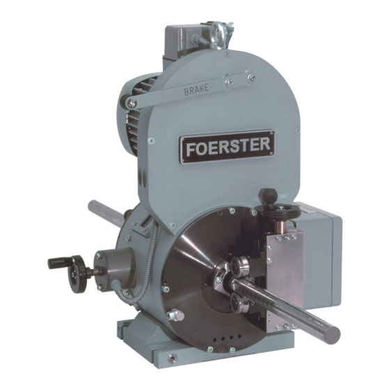
- Page 1 ® CIRCOGRAPH Sensor system Ro 35 L 6.461.21 Operating Instructions...
- Page 3 INTRODUCTION These Operating Instructions are intended to be read, understood and observed in all points by the persons responsible for operating the equip- ment. The complete Operating Instructions consist of the following sections: Safety Description Installation Operation Maintenance Knowledge of the Operating Instructions is essential for avoiding equip- ment faults and for ensuring trouble-free operation.
- Page 4 These operating instructions are intended for assembly, operating and monitoring personnel. Copying, reproduction or translation of these oper- ating instructions into other languages in whole or in part requires the ex- press written approval of INSTITUT DR. FOERSTER GmbH & Co. KG.
-
Page 5: Table Of Contents
SENSOR SYSTEM Ro 35 L CONTENTS SAFETY ........................1-1 Dangers posed by this machine ...................1-1 Safety information and tips...................1-1 Use as intended ......................1-2 Dangers posed by accessories ..................1-2 Emissions ........................1-2 Danger sources ......................1-3 Workstations.........................1-3 Authorised operators ....................1-3 Personal safety equipment...................1-4 1.10 Safety measures at the installation location ..............1-4 1.11 Protective safety devices .....................1-4 1.12 Behaviour in the event of an emergency..............1-4... - Page 6 SENSOR SYSTEM Ro 35 L CONTENTS INSTALLATION......................3-1 Setup and Connection....................3-1 OPERATION......................4-1 Dimension change .......................4-1 Selection and installation of the protective nozzles............4-2 4.2.1 Selection of the protective nozzles ..............4-2 4.2.2 Required tools ....................4-4 Adjusting nominal diameter ..................4-5 4.3.1 Preparation .......................4-5 4.3.2 Removing nozzle holder ...................4-6 4.3.3...
-
Page 7: Safety
SENSOR SYSTEM Ro 35 L SAFETY 1.1 Dangers posed by this machine 1 SAFETY 1.1 Dangers posed by this machine The sensor system features protective safety devices. It has been sub- jected to a safety test and safety acceptance test. In the event of operat- ing errors or misuse, the machine may pose dangers and risks to the life and limb of the operator, the machine and other operator’s valuables and... -
Page 8: Use As Intended
SENSOR SYSTEM Ro 35 L 1.3 Use as intended SAFETY 1.3 Use as intended The sensor system is suitable only for non-destructive testing of round material. Diameter range: see 2.4 Technical Data Smaller diameters and larger diameters may not be admitted into the sensor system under any circumstances. -
Page 9: Danger Sources
SENSOR SYSTEM Ro 35 L SAFETY 1.6 Danger sources 1.6 Danger sources The sensor system operates with a rotating test system and an attached roller guide system during operation. A person coming into contact with the roller guide or the rotating test system may suffer very serious injuries. Switch off the drives before you put your hands into or touch the sensor system. -
Page 10: Personal Safety Equipment
SENSOR SYSTEM Ro 35 L 1.9 Personal safety equipment SAFETY 1.9 Personal safety equipment You are to wear ear plugs, if the A-weighted equivalent sound pressure level at the workstations of the sensor system is greater than 85 dB(A). Sound pressure level for this equipment: see 2.4 Technical Data 1.10 Safety measures at the installation location The sensor system must be installed stably on a machine foundation pro- vided for it and must be firmly anchored to the foundation. -
Page 11: Declaration Of Conformity
SENSOR SYSTEM Ro 35 L SAFETY 1.13 Declaration of Conformity 1.13 Declaration of Conformity DECLARATION of CONFORMITY Manufacturer: INSTITUT DR. FOERSTER GmbH & Co. KG Phone +49 7121 140-0 In Laisen 70 +49 7121 140-488 72766 REUTLINGEN info@foerstergroup.de GERMANY www.foerstergroup.de Product: CIRCOGRAPH®... - Page 12 SENSOR SYSTEM Ro 35 L 1.13 Declaration of Conformity SAFETY Notes: 6.461.21 - 2008/06...
-
Page 13: Description
SENSOR SYSTEM Ro 35 L DESCRIPTION 2.1 Application 2 DESCRIPTION 2.1 Application Non-destructive testing of ferromagnetic, austenitic and non- ferromagnetic round materials (wires, bars and tubes) for surface flaws in ® conjunction with the CIRCOGRAPH DS 6.430 testing and evaluation electronic equipment and a suitable mechanical handling system. -
Page 14: Mode Of Operation
SENSOR SYSTEM Ro 35 L 2.2 Mode of operation DESCRIPTION 2.2 Mode of operation The sensor system operates on the basis of the eddy current principle in accordance with EN 12084. Rotating systems are used to detect longitu- dinal surface defects. Probes rotate at high speed and without physical contact around the test piece. -
Page 15: Construction
SENSOR SYSTEM Ro 35 L DESCRIPTION 2.3 Construction 2.3 Construction Fig. 2.1 Test equipment configuration CIRCOGRAPH DS CIRCOGRAPH DS test electronics and the connection cables are re- quired for a complete test system, besides the sensor system which scans the test material and generates the eddy-current signal. Separate leaflet: “CIRCOGRAPH DS System 6.430”, Order-No. - Page 16 SENSOR SYSTEM Ro 35 L 2.3 Construction DESCRIPTION Nozzle Holder Outside Nozzle Outside Nozzle Inside Nozzle Holder Inside Roller guide left Roller guide right ∅ 4.5 – 35 ∅ 4.5 – 35 6.461.01-5001 6.461.01-5011 Throughput preferred direction (both directions possible) Fig.
-
Page 17: Test Heads
SENSOR SYSTEM Ro 35 L DESCRIPTION 2.3 Construction In order to withstand the rough conditions of use, the rotating head has been designed to be dust-protected, robust and reliable by means of complex constructional measures such as labyrinth seals and dirt deflec- tors. - Page 18 SENSOR SYSTEM Ro 35 L 2.3 Construction DESCRIPTION 2.3.1 Test Heads The test heads are both the heart of the sensor system and its most criti- cal components. They consist of an eddy-current probe with field, measuring and clear- ance windings which are installed in a precise mechanical holder and are connected by means of a highly flexible special cable with a connection plug.
- Page 19 SENSOR SYSTEM Ro 35 L DESCRIPTION 2.3 Construction 2.3.2 Rotating Head Ro 35 L The rotating head is the main component of the sensor system. It consists of: rotor transmitter drive housing rotating head electronics The test direction can be selected as right or left (viewed in the throughput direction).
- Page 20 SENSOR SYSTEM Ro 35 L 2.3 Construction DESCRIPTION Transmitter Wear-resistant rotating transmitter in disc-type construction with a field transmitter, two measuring channels and a clearance channel. Consisting of a rotor and stator, it transmits the field current for the rotat- ing probes from the stator to the rotor and, in the opposite direction, transmits the test signal to the test electronics for evaluation.
- Page 21 SENSOR SYSTEM Ro 35 L DESCRIPTION 2.3 Construction Drive Indestructible 3-phase drive with a cage motor in conformance with stan- dards. External motor control for power supply to the drive. The following versions are available: MOC E motor control fixed rotational speed of 4,500 rpm at 50 Hz mains supply reasonably priced version, recommended for test speeds at which a ro- tational speed of 4,5000 rpm is sufficient for gapless testing (cf.
- Page 22 SENSOR SYSTEM Ro 35 L 2.3 Construction DESCRIPTION Diameter adjustment Diameter adjustment is carried out manually with a hand wheel. The lin- ear scale is located on the rotor. The diameter can be adjusted with an accuracy of 0.1 mm. Protective nozzles standard The protective nozzles have a dual function: They protect the test heads from damage, particularly during entry...
- Page 23 2.3 Construction Entry and exit nozzles must always be used in pairs with the same nomi- nal value. Protective nozzles can be ordered from INSTITUT DR. FOERSTER or can be manufactured by the customer on the basis of drawings. WARNING! Operation without protective nozzles is not permitted for damage and safety reasons.
- Page 24 SENSOR SYSTEM Ro 35 L 2.3 Construction DESCRIPTION Roller guide The roller guides have two advantages: In set-up mode, a calibration piece with reference flaws can be held cen- trically outside the testing line and the test electronics can be adjusted simply, since the rotating probes periodically scan the test flaw and dis- play the signal quasi-statically.
-
Page 25: Technical Data
SENSOR SYSTEM Ro 35 L DESCRIPTION 2.4 Technical Data 2.4 Technical Data Ro 35 L Diameter range test material continuously adjustable 2 or 4 test heads 5 to 35 mm Rotational speed MOC E motor control 4,500 rpm MOC S/SB motor control 4,500 or 9,000 rpm Deceleration times from 9,000 rpm... -
Page 26: Dimension Sheet
SENSOR SYSTEM Ro 35 L 2.5 Dimension sheet DESCRIPTION 2.5 Dimension sheet Fig. 2.9 Dimension sheet 1 2-14 6.461.21 - 2008/06... - Page 27 SENSOR SYSTEM Ro 35 L DESCRIPTION 2.5 Dimension sheet Fig. 2.10 Dimension sheet 2 2-15 6.461.21 - 2008/06...
-
Page 28: Environmental Conditions
-20° C to +70° C max. relative humidity 95 %, condensation not permissible maximum storage duration approx. 12 months (extension possible after intermediate check by FOERSTER employee) Emissions The A-weighted sound pressure level at intervals of 1 m from the ma- chine's surface and at 1.60 m height is for maximum rotational speed... -
Page 29: Standard Components
SENSOR SYSTEM Ro 35 L DESCRIPTION 2.7 Standard Components 2.7 Standard Components Designation Drawing-No. Order-No Rotating head Ro 35 L 6.461.21-1002 1665766 Test cable DS 10M, CIRCOGRAPH-DS 6.460.01-9921 1650785 Motor cable 10M 6.460.01-9931 1638343 Grounding cable 10M 1.175-0061 1554034 Test head, BS=2.5 6.461.21-2025 1660969 Test head, BS=5... - Page 30 SENSOR SYSTEM Ro 35 L 2.7 Standard Components DESCRIPTION Notes: 2-18 6.461.21 - 2008/06...
-
Page 31: Installation
SENSOR SYSTEM Ro 35 L INSTALLATION 3.1 Setup and Connection 3 INSTALLATION 3.1 Setup and Connection NOTE! The sensor system must be mounted on a horizontally shiftable lifting table in order to be able to change the dimensions or to carry out ser- vice work outside of the testing line. - Page 32 SENSOR SYSTEM Ro 35 L 3.1 Setup and Connection INSTALLATION Electrical connections Connection motor cable Connection testing cable Fig. 3.2 Rotating head, connections Remote Remote cable (option) Motor control Cooling air Power line Motor cable 10 m 6.460.01-9931 Testing cable 10 m 6.460.01-9921 Test Electronics Light barrier...
-
Page 33: Operation
SENSOR SYSTEM Ro 35 L OPERATION 4.1 Dimension change 4 OPERATION 4.1 Dimension change The following steps must be carried out during conversion: Set test head to new nominal value of test material Insert suitable protective nozzles Set roller guides to test diameter Centre sensor system in the testing line Preparation Select protective nozzles for new test piece measurement. -
Page 34: Selection And Installation Of The Protective Nozzles
Tab. 4.1 Target nozzle grading for D = nominal diameter of test material DD = nominal size of protective nozzles The FOERSTER standard protective nozzle range is based on the grad- ing recommendation above. The protective nozzles can be selected more precisely depending on the test diameter if the quality of guidance is sufficiently precise. - Page 35 SENSORSY STEM Ro 35 L OPERATION 4.2 Selection and installation of the protective nozzles Standard nozzle Important! Do not slide the test material in and out without nozzle – risk of major damage. Operate only with protective nozzles! Nozzle Outside Drawing No. Nominal dimension mm Step mm Standard...
-
Page 36: Required Tools
SENSOR SYSTEM Ro 35 L 4.2 Selection and installation of the protective nozzles OPERATION 4.2.2 Required tools Tool Order-No Hexagon screwdriver, straight 016 851 3 a/f 5 x 200 mm, T-handle Hexagon screwdriver, straight 012 013 8 a/f 4 mm, spherical head Hexagon screwdriver, straight 014 038 4 a/f 3 x 100 mm, T-handle... -
Page 37: Adjusting Nominal Diameter
SENSORSY STEM Ro 35 L OPERATION 4.3 Adjusting nominal diameter 4.3 Adjusting nominal diameter 4.3.1 Preparation Select protective nozzles according to Chapter 4.2. Switch off drive and wait for standstill. Move test material out of the sensor system. Move sensor system out of the testing line. Safety switch Cover lock Rotor cover... -
Page 38: Removing Nozzle Holder
SENSOR SYSTEM Ro 35 L 4.3 Adjusting nominal diameter OPERATION 4.3.2 Removing nozzle holder Adjustment side Open roller guides with hand wheel until the nozzle holder is accessible. Undo fastening of outside nozzle holder. Turn outside nozzle holder ant-clockwise. Remove nozzle holder 2 hexagon sockets 5 mm Fig. - Page 39 SENSORSY STEM Ro 35 L OPERATION 4.3 Adjusting nominal diameter Drive side Open roller guides with hand wheel until nozzle holder is accessible. Undo fastening of inside nozzle holder. Turn inside nozzle holder anti-clockwise. Remove inside nozzle holder 2 hexagon sockets 5 mm Fig.
-
Page 40: Changing Nozzles
SENSOR SYSTEM Ro 35 L 4.3 Adjusting nominal diameter OPERATION 4.3.3 Changing nozzles Unscrew the nozzles from the nozzle holder using two hook spanners. CAUTION! If the nozzle holder is fixed in a vice, clamp on the surfaces only! Outside nozzle holder Hook spanner Outside protective nozzle Inside protective nozzle... -
Page 41: Adjusting Probe Clearance
SENSORSY STEM Ro 35 L OPERATION 4.3 Adjusting nominal diameter 4.3.4 Adjusting probe clearance The test heads are adjusted to the nominal diameter (clear opening) of the protective nozzles by a hand wheel. A standstill detection facility installed in the adjusting device prevents ac- tuation until the rotating head has come to a standstill. - Page 42 SENSOR SYSTEM Ro 35 L 4.3 Adjusting nominal diameter OPERATION WARNING! Actuate diameter adjustment during standstill only! The adjusting device first turns the rotor to adjustment position and then adjusts the nominal diameter to the new material value. Operation side The marking can be seen in the center of the display window when the ro- tor is in adjustment position.
- Page 43 SENSORSY STEM Ro 35 L OPERATION 4.3 Adjusting nominal diameter Alternative: end face Open rotor cover. To do this, pull the ball handle and swivel out the locking plate. NOTE! The setting ring for nominal dimension adjustment is self-locking. Hand wheel Fig.
- Page 44 SENSOR SYSTEM Ro 35 L 4.3 Adjusting nominal diameter OPERATION Changing adjustment value NOTE! Brake the rotating head to a standstill with the hand brake before adjustment! Fig. 4.13 Idle position Push in the hand wheel and turn until the actually valid diameter has reached the adjustment position.
-
Page 45: Adjusting Roller Guide
SENSORSY STEM Ro 35 L OPERATION 4.4 Rotational speed preselection 4.3.5 Adjusting roller guide Open roller guide in accordance with material diameter. Insert test material. Adjust roller guide so that the rollers just touch the test material. NOTE! The test piece must run centrically through the sensor system, if nec- essary adjust the table to the height of the test axis and lock. -
Page 46: Switching On Motor
SENSOR SYSTEM Ro 35 L 4.5 Switching on motor OPERATION 4.5 Switching on motor NOTE! Check the diameter and height settings of the sensor system before switching on. The operating elements used to switch on the rotating head drive are lo- cated on the motor control. -
Page 47: Application Drawing Line
SENSORSY STEM Ro 35 L OPERATION 4.6 Application drawing line 4.6 Application drawing line Dimension change - definitions Position of the test heads, testing without physical contact and with excel- lent centering of the test material. Normal setting for correct diameter setting and correct nominal diameter of protective nozzle;... - Page 48 SENSOR SYSTEM Ro 35 L 4.6 Application drawing line OPERATION Example: Test piece Ø Nominal Ø nozzle Scale value 7 mm 12 mm 13.0 13.0 20 mm 21.5 21.5 30 mm 32.0 32.0 34 mm 36.0 36.0 Selecting and fitting the protective nozzles WARNING! Do not slide the test material in or out without nozzles.
-
Page 49: Maintenance
SENSOR SYSTEM Ro 35 L MAINTENANCE 5.1 Maintenance schedule 5 MAINTENANCE 5.1 Maintenance schedule WARNING! Risk of injury! Always switch off the drive and wait for the machine to stop before per- forming work of any kind! Do not touch or tamper with the sensor system, with the rotating unit operating! Deceleration times: without braking approx. -
Page 50: Cleaning
SENSOR SYSTEM Ro 35 L 5.2 Cleaning MAINTENANCE 5.2 Cleaning WARNING! Do not use solvent cleaner, petrol or alcohol! Use commercially available cleaning agents. Observe the instructions for use from the respective cleaning agent manufacturer. Make sure the areas around the rotating parts are clean! Remove abrasion and dirt with an industrial vacuum cleaner. -
Page 51: Removing And Installing Test Heads
SENSORSY STEM Ro 35 L MAINTENANCE 5.3 Removing and installing test heads 5.3 Removing and installing test heads 5.3.1 Removing test heads NOTE! Make sure the plug contacts are clean! You must not open the lock nut and locking screw. Swivel cover outwards or remove. - Page 52 SENSOR SYSTEM Ro 35 L 5.3 Removing and installing test heads MAINTENANCE Remove ring: WARNING! The ring is spring-loaded and will get loose as soon as the screws are pulled off! Undo four M6x10 DIN 912 hexagon socket screws (1). Remove ring (2).
- Page 53 SENSORSY STEM Ro 35 L MAINTENANCE 5.3 Removing and installing test heads Take out test levers: Undo the plug connection of the test head cable. NOTE! The screws are undetachable! Pull the test head outwards in axial direction. Clean pivot pin and test lever bearing (roller bearing), grease lightly if necessary.
-
Page 54: Installing Test Heads
SENSOR SYSTEM Ro 35 L 5.3 Removing and installing test heads MAINTENANCE Installing test heads CAUTION! Use test heads as a set with the same specifications. The type number is found on the side of the test heads. Clean all parts, especially the contact surfaces. DANGER! Risk of injury! Balancing of the rotating head only... - Page 55 SENSORSY STEM Ro 35 L MAINTENANCE 5.3 Removing and installing test heads Push the test levers in the shown order onto the pivot pins and join to the adjusting lever. Push Join Fastening screws Fig. 5.7 Fig. 5.8 Insert the plug connection of the test head cable; lock fastening screws. Fig.
-
Page 56: List Of Parts Subject To Wear
SENSOR SYSTEM Ro 35 L 5.4 List of parts subject to wear MAINTENANCE Rotate ring to the end position and secure with four hexagon socket screws M6x10 DIN 912, while checking the mobility of test levers. Fit lid (pay attention to position of pin) and secure with five hexagon socket screws M6x10 DIN 912. - Page 57 Institut Dr. Foerster GmbH & Co. KG Division TS Semi-finished Product Testing In Laisen 70 72766 REUTLINGEN GERMANY Telephone: +49 7121 140-270 Fax: +49 7121 140-459 E-mail: ts@foerstergroup.de Internet: www.foerstergroup.de 6.461.21 UA06/EN Order no.: 166 479 4 Edition: 06/2008 Author:...
Need help?
Do you have a question about the CIRCOGRAPH Ro 35 L and is the answer not in the manual?
Questions and answers