
Related Manuals for Seres OL TOC


Summary of Contents for Seres OL TOC
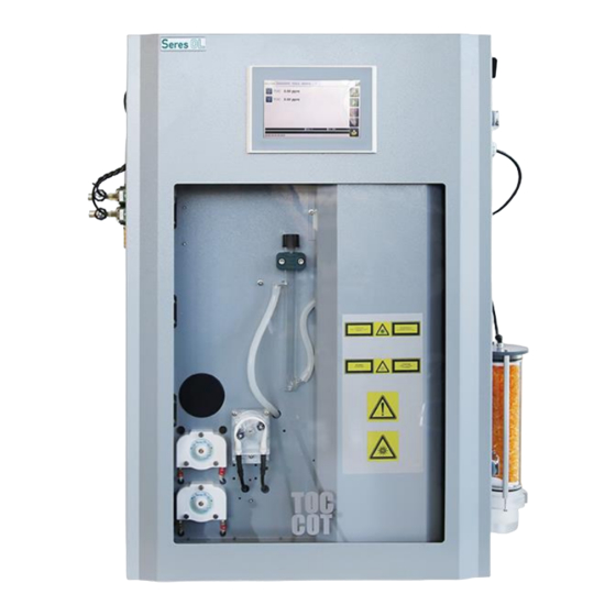
- Page 1 N°10844_revS User and Maintenance Manual Online analyzer for TOC monitoring in water This document is the property of SERES and cannot be reproduced without authorization...
-
Page 2: List Of Versions And Approvals
DALIA Nicolas 08/2020 Removal of items not present in the new DALIA Nicolas DALIA Nicolas 10/2020 SERES OL catalog at the SWAN takeover: dilution range, … Update ISO certificate + Zero cycle DALIA Nicolas DALIA Nicolas 02/2021 Update CE/UKCA Declaration... -
Page 3: Table Of Contents
TOC EVOLUTION: 3/74 Page: USER & MAINTENANCE MANUAL Instructions No.: 10844 2 CONTENTS LIST OF VERSIONS AND APPROVALS ___________________________________________________________ 2 CONTENTS ____________________________________________________________________________________ 3 WARRANTY CONDITIONS ______________________________________________________________________ 6 3.1. __________________________ 6 EMINDER OF THE MAIN WARRANTIES CONDITIONS APPLICABLE TO THE ANALYSER 3.2.1. - Page 4 EGULAR MAINTENANCE 11.2.1 TOC calibration ___________________________________________________________________________________ 56 11.2.2 Manual measure TOC ______________________________________________________________________________ 58 11.2.3 Zero calibration TOC (only if activated by SERES) ______________________________________________________ 59 Maintenance cycle – Periodic trigger (option) ___________________________________________________________ 59 11.2.4 11.2.5 Reagent change ____________________________________________________________________________________ 60 11.2.6 Replacing the pump pipes ___________________________________________________________________________ 60 11.2.7...
- Page 5 TOC EVOLUTION: 5/74 Page: USER & MAINTENANCE MANUAL Instructions No.: 10844 11.3.7 The Condenser ____________________________________________________________________________________ 68 11.3.8 Replacing the heated down conductor __________________________________________________________________ 69 11.3.9 Replacing the mass controller ________________________________________________________________________ 70 11.3.10 Replacing the Air filter ______________________________________________________________________________ 71 REPAIR MANUAL _____________________________________________________________________________ 72 12.1...
-
Page 6: Warranty Conditions
TOC EVOLUTION: 6/74 Page: USER & MAINTENANCE MANUAL Instructions No.: 10844 3 Warranty conditions 3.1. Reminder of the main warranties conditions applicable to the analyser Our general terms of warranty are applied to this analyser and integrated in our general terms of sale downloadable on our website. -
Page 7: International Symbols Recognised By Manufacturer
TOC EVOLUTION: 7/74 Page: USER & MAINTENANCE MANUAL Instructions No.: 10844 3.2. International symbols recognised by Manufacturer 3.3. Symbol Standard Description IEC 60417, No. 5016 Electrical fuse IEC 60417, No. 5017 Ground IEC 60417, No. 5021 Equipotentiality IEC 60417, No. 5032 Alternative current IEC 60417, No. -
Page 8: The Book
TOC EVOLUTION: 8/74 Page: USER & MAINTENANCE MANUAL Instructions No.: 10844 3.6. The book The information contained in this book may be subject of any changes without notice beforehand and don’t represent any engagement on behalf of Manufacturer. Manufacturer reserves the right to make changes in the construction, design, specifications, and / or in the procedures that cannot be reflected in the book. -
Page 9: Unpacking Book
TOC EVOLUTION: 9/74 Page: USER & MAINTENANCE MANUAL Instructions No.: 10844 4 Unpacking book 4.1 Precaution Position the box corectly (Up/Down) Unpack carefully the analyser Check the analyzer for damage o If the device seems to be damaged, don’t plug it and get into touch with the After Sale Service Department immediately (contact in Chapter Warranty). - Page 10 TOC EVOLUTION: 10/74 Page: USER & MAINTENANCE MANUAL Instructions No.: 10844 SECTION 1 EQUIPMENT FILE 5. INTRODUCTION 6. MEASURING PRINCIPLE 7. TECHNICAL SPECIFICATIONS 8. DESCRIPTION OF THE EQUIPMENT This document is the property of SERES and cannot be reproduced without authorization...
-
Page 11: Introduction
In addition, we have the "COD Correlation" configuration possible. By measuring TOC we can deduce the oxygen demand (COD) of the sample analyzed. Indeed a linear correlation coefficient can be applied* between the TOC and the COD of the form: COD = A * TOC + B... -
Page 12: Measuring Principle
TOC EVOLUTION: 12/74 Page: USER & MAINTENANCE MANUAL Instructions No.: 10844 6 Measuring principle The measurement of organic carbon, based on the cold oxidation principle, can be represented as follows: - Preparation of the sample - Oxidation of organic matter... -
Page 13: Co 2 Measurement
TOC EVOLUTION: 13/74 Page: USER & MAINTENANCE MANUAL Instructions No.: 10844 measurement The measurement is based on the absorption of an infrared radiation by the CO 2 molecule. The measuring vessel is temperature-controlled. “ ” It is an NDIR measuring system (NDIR: Non Dispersive IR) operating with a... -
Page 14: Characteristics Of The Measuring Method
TOC EVOLUTION: 14/74 Page: USER & MAINTENANCE MANUAL Instructions No.: 10844 Characteristics of the measuring method The characteristic values of the method are expressed as a percentage on Full scale. Measuring system NDIR Low-range configuration 0-2 ppm Limit of Detection 0.01 ppm Repeatability ±... -
Page 15: Calibration And Testing
** Only for ranges <20ppm. The “Manual measure on TIC” and “Zero measure” may not be present on the analyser according to the situation. If this is the case, only use the “TOC Calibration” and “Manual Measure TOC” Zero measure*... -
Page 16: Measuring Cycle
TOC EVOLUTION: 16/74 Page: USER & MAINTENANCE MANUAL Instructions No.: 10844 TOC standards Validity limit and Monthly Name Reference Storage Toxicity consumption conditions 1 week in a cool Potassium hydrogen R01130MG50 300ml place phtalate In order to obtain a solution of 1 g/l: - Dissolve 2.125 g of potassium hydrogen phtalate... -
Page 17: Hydraulic Diagrams
TOC EVOLUTION: 17/74 Page: USER & MAINTENANCE MANUAL Instructions No.: 10844 Hydraulic diagrams Figure 1: Hydraulic diagram 1 channel. This document is the property of SERES and cannot be reproduced without authorization... - Page 18 TOC EVOLUTION: 18/74 Page: USER & MAINTENANCE MANUAL Instructions No.: 10844 Figure 2: Multi Channel Hydraulic diagram. This document is the property of SERES and cannot be reproduced without authorization...
-
Page 19: Technical Specifications
TOC EVOLUTION: 19/74 Page: USER & MAINTENANCE MANUAL Instructions No.: 10844 7 Technical specifications The environment Recommendations for the facility: Room temperature between 5 and 40°C maximum 7.2 Characteristics 7.2.1 Measuring ranges 3 measuring ranges are available in two versions:... -
Page 20: Sample Outlet
TOC EVOLUTION: 20/74 Page: USER & MAINTENANCE MANUAL Instructions No.: 10844 7.2.6 Sample outlet Free outlet, not closed (atmospheric pressure) 7.2.7 Instrument air inlet For the measurement: – Pressure: 3 bar maximum Adjustment at 0.5-1bar Type of air: No humidity (dry air) -
Page 21: Description Of The Equipment
TOC EVOLUTION: 21/74 Page: USER & MAINTENANCE MANUAL Instructions No.: 10844 8 Description of the equipment Description of the analyser In order to simplify the facility, the equipment is equipped with wall-mounting devices. This box casing is divided into two compartments, the top part accommodates the electronic system (external communication, display) and the bottom part the hydraulic system. - Page 22 TOC EVOLUTION: 22/74 Page: USER & MAINTENANCE MANUAL Instructions No.: 10844 Figure 3: General dimensional drawing (1 channel). This document is the property of SERES and cannot be reproduced without authorization...
- Page 23 TOC EVOLUTION: 23/74 Page: USER & MAINTENANCE MANUAL Instructions No.: 10844 Figure 4: General dimensional drawing (Multi channel configuration). This document is the property of SERES and cannot be reproduced without authorization...
-
Page 24: Description Of The Sub-Assemblies
TOC EVOLUTION: 24/74 Page: USER & MAINTENANCE MANUAL Instructions No.: 10844 8.2 Description of the sub-assemblies 8.2.1 Collection of the sample volume A certain volume is to be collected in order to analyse the Organic Carbon in the sample. The volume is collected by means of a peristaltic pump and a calibrated coil. -
Page 25: The Multi-Function Reactor (Oxidation)
TOC EVOLUTION: 25/74 Page: USER & MAINTENANCE MANUAL Instructions No.: 10844 8.2.4 The multi-function reactor (oxidation) The Reactor can be used for the oxidation of Organic Carbon. It contains a volume of the sample to by oxidised. It comprises a special UV lamp, glassware and an injection/distribution/draining system. -
Page 26: The Liquid Seal (Sample Overflow And Pressure Drop Security)
TOC EVOLUTION: 26/74 Page: USER & MAINTENANCE MANUAL Instructions No.: 10844 Gas evacuation at the outlet of ozone destroyer to the external atmosphere 8.2.7 The Liquid Seal (Sample Overflow and Pressure Drop Security) This system ensures safety in the event of a sample overload inside the reactor. It also ensures safe conditions in the event of a pressure drop (clogging material or other). -
Page 27: Carbon Treatment Cartridge
TOC EVOLUTION: 27/74 Page: USER & MAINTENANCE MANUAL Instructions No.: 10844 This controller can be combined with a pressure controller if the client does not have one in his facility. Air filter Pressure control - Air inlet (Cartridge) Weight controller 8.2.10... -
Page 28: The Compressor
TOC EVOLUTION: 28/74 Page: USER & MAINTENANCE MANUAL Instructions No.: 10844 8.2.12 The compressor The air required for the operation of the analyser is particle-free dry air. This air is generated thanks to the "Compressor" coupled with a "silica gel cartridge". -
Page 29: The Measuring Board
TOC EVOLUTION: 29/74 Page: USER & MAINTENANCE MANUAL Instructions No.: 10844 Communication cable USB port Power supply cable Figure 6: Connection details. 8.2.15 The Measuring Board The measuring board comprises the controls for the analyser components and the measuring part. -
Page 30: The Input/Output Board
TOC EVOLUTION: 30/74 Page: USER & MAINTENANCE MANUAL Instructions No.: 10844 8.2.16 The Input/Output Board This board comprises the client interface functionalities. 8.2.16.1 Power Supply & Communication This board is directly connected to the power supply observed previously. It communicates with the PLC board through an Ethernet connection via an Ethernet Switch. - Page 31 TOC EVOLUTION: 31/74 Page: USER & MAINTENANCE MANUAL Instructions No.: 10844 Direction Type Number Board W1128001 Board W1128007 (Multi channel) – (Address: 1 N=0) board Name Function Name Function 4-20mA 4/20mA Digital 4-20mA 4/20mA Digital Channel 2 RELAY 1 D.C. Reserved RELAY 1 D.C.
- Page 32 TOC EVOLUTION: 32/74 Page: USER & MAINTENANCE MANUAL Instructions No.: 10844 8.2.16.3 Input/output cabling 8.2.16.3.1 Wiring of the 4-20mA outputs representing the measurement (4-20mA) The 4-20mA outputs, representing the chemical value of the parameter being measured by the analyser, are accessible on pins 1(GND) and 2 (+) for outputs No. 1 and 3(GND) & 4 (+) for output No. 2 of connector J14 of the board.
- Page 33 TOC EVOLUTION: 33/74 Page: USER & MAINTENANCE MANUAL Instructions No.: 10844 8.2.16.3.5 Wiring of the ‘sample default’ channel information (RELAY 4) ” "sample default information is accessible on pins 10, 11 & 12 of connector J9 as a dry contact.
-
Page 34: Description Of The Screen Menus
TOC EVOLUTION: 34/74 Page: USER & MAINTENANCE MANUAL Instructions No.: 10844 8.3 Description of the screen menus 8.3.1 Description of the Main screen 1. Menu tabs 7. Measuring menu 8. Measured concentrations 2. Alarms 3. Play/Pause/Stop 9.Channel in 4. End of cycle... - Page 35 TOC EVOLUTION: 35/74 Page: USER & MAINTENANCE MANUAL Instructions No.: 10844 Tools Tab: Access to the Maintenance, Options, Log file copy, Electrical Tests and History menus. (Non contractual photo) Maintenance Menu: Calibrations and Manual measurement. Options: To set the parameters of certain setpoints, the date/time, etc.
-
Page 36: Measurement Menu (Measurement Data, Thresholds, Coefficient, Etc.)
TOC EVOLUTION: 36/74 Page: USER & MAINTENANCE MANUAL Instructions No.: 10844 8.3.2 Measurement Menu (Measurement data, thresholds, coefficient, etc.) From the main screen: Press of the relevant channel Enter the authorised user code The Measurement window appears:... - Page 37 TOC EVOLUTION: 37/74 Page: USER & MAINTENANCE MANUAL Instructions No.: 10844 o Press the “ ” Pump tab. o Press ON to enable the pump or OFF to disable it. In order to enable the Sample peristaltic pump, o Press ON to enable the pump or OFF to disable it - “...
- Page 38 TOC EVOLUTION: 38/74 Page: USER & MAINTENANCE MANUAL Instructions No.: 10844 o Press the "Solenoid" tab. Press ON to enable or OFF to disable. 8.3.3.1.4 Actuator tab In order to control the UV lamp, heating, compressor: o Press the “...
- Page 39 TOC EVOLUTION: 39/74 Page: USER & MAINTENANCE MANUAL Instructions No.: 10844 o Test the relevant output for the 3 output levels: 0%, 50% and 100%, respectively, 4, 12 and 20 mA. To do this, press the corresponding button. 8.3.3.1.6 Client input tab This window allows you to visualise the state of the inputs.
- Page 40 TOC EVOLUTION: 40/74 Page: USER & MAINTENANCE MANUAL Instructions No.: 10844 The air flowrate setpoint is the flowrate of the controller. The NDIR temperature setpoint (°C) is the temperature of the measuring vessel. The condenser temperature setpoint (°C) is the control temperature of the condenser.
- Page 41 TOC EVOLUTION: 41/74 Page: USER & MAINTENANCE MANUAL Instructions No.: 10844 SECTION 2 INSTALLATION MANUAL 9.1. LOCATION 9.2. FASTENING 9.3. ELECTRICAL CONNECTIONS 9.4. HYDRAULIC CONNECTIONS This document is the property of SERES and cannot be reproduced without authorization...
-
Page 42: Installation Manual
An outlet to the outside atmosphere for discharging the measured gasses. 9.2 Mounting conditions TOC Evolution can be mounted onto a vertical wall by means of four M10 bolts (refer to the assembly drawing) with, if possible, the MMI at eye level for easy maintenance. - Page 43 TOC EVOLUTION: 43/74 Page: USER & MAINTENANCE MANUAL Instructions No.: 10844 The power supply to the analyzer must be connected downstream of a secured electrical installation in accordance with local standards. For a 110V supply, a special set is present in the analyzer.
-
Page 44: Communication
TOC EVOLUTION: 44/74 Page: USER & MAINTENANCE MANUAL Instructions No.: 10844 9.3.2 Communication Figure 9 : Input / output board terminal drawing (1 channel) “ ” For more information, consult chapter 8.2.14.2 Wiring of the inputs/outputs This document is the property of SERES and cannot be reproduced without authorization... - Page 45 TOC EVOLUTION: 45/74 Page: USER & MAINTENANCE MANUAL Instructions No.: 10844 Figure 10: Input / output board terminal drawing (Multi channel). This document is the property of SERES and cannot be reproduced without authorization...
-
Page 46: Jbus Connection (Rs485)
TOC EVOLUTION: 46/74 Page: USER & MAINTENANCE MANUAL Instructions No.: 10844 9.3.3 JBUS connection (RS485) There are 2 possibilities for communication between the analyzer and the customer. The protocol used is the JBUS and the connectivity can be done either by RS485 or TCP / IP (Ethernet). - Page 47 TOC EVOLUTION: 47/74 Page: USER & MAINTENANCE MANUAL Instructions No.: 10844 To set the JBUS slave number, go to the "Tools" tab, "Options"menu. The slave address is: 55 (by default). JBUS by TCP/IP When the client wants to connect via Ethernet, the analyzer is equipped with a converter at the top of the device.
-
Page 48: Hydraulic Connections
TOC EVOLUTION: 48/74 Page: USER & MAINTENANCE MANUAL Instructions No.: 10844 9.4 Hydraulic connections 9.4.1 Sample to be analysed To minimise the response time, the sample line connecting the sampling point to the device will be as short as possible. - Page 49 TOC EVOLUTION: 49/74 Page: USER & MAINTENANCE MANUAL Instructions No.: 10844 SECTION 3 USER MANUAL This document is the property of SERES and cannot be reproduced without authorization...
-
Page 50: User Manual
TOC EVOLUTION: 50/74 Page: USER & MAINTENANCE MANUAL Instructions No.: 10844 10 User manual 10.1 Preliminary start-up Before switching the analyser ON, check all the electrical and hydraulic connections. Possibly ” refer to the "Technical Specifications chapters. Adjust the sample flowrate. -
Page 51: Pump Priming
TOC EVOLUTION: 51/74 Page: USER & MAINTENANCE MANUAL Instructions No.: 10844 Press button Enter the authorised user code. 10.4 Pump priming Press the “ ” Tools tab. Enter the authorised user code. Access the Electrical test menu ... -
Page 52: Setting The Parameters Of The 4-20 M Arange
TOC EVOLUTION: 52/74 Page: USER & MAINTENANCE MANUAL Instructions No.: 10844 The Measurement window appears: Press on the value of the threshold to modify them. 10.6 Setting the parameters of the 4-20 mA range From the main screen: ... -
Page 53: Timing Of Sample Purging Line (Option On Specific Customer Request)
TOC EVOLUTION: 53/74 Page: USER & MAINTENANCE MANUAL Instructions No.: 10844 10.7 Timing of sample purging line (Option on specific customer request) If this option is requested, it is possible to put a time before starting the analysis. This time corresponds to the purge time of the sample line in the event of distance between the analyzer and the customer's sampling point. -
Page 54: Stopping The Analyser
TOC EVOLUTION: 54/74 Page: USER & MAINTENANCE MANUAL Instructions No.: 10844 This type of file can be opened with an Excel application. 10.10 Stopping the analyser If the analyser must be stopped for a few days or more, it is always best to condition it so that everything goes well when it is restarted. - Page 55 TOC EVOLUTION: 55/74 Page: USER & MAINTENANCE MANUAL Instructions No.: 10844 SECTION 4 MAINTENANCE MANUAL This document is the property of SERES and cannot be reproduced without authorization...
-
Page 56: Maintenance Manual
11.2 Regular maintenance Multi-channel configuration: with regard to the cycles present in "maintenance", they are carried out only by the standard inlet of the TOC and on channel 1 only. 11.2.1 TOC calibration It is recommended to carry out at least 2 to 3 calibration cycles to ensure correct setting of the analyzer. - Page 57 TOC EVOLUTION: 57/74 Page: USER & MAINTENANCE MANUAL Instructions No.: 10844 A “ ” Standard Value window appears. Check that the "standard" value is identical to the concentration of your standard (check the concentration unit). If this is not the case: o Press the value.
-
Page 58: Manual Measure Toc
Enter the authorised user code. Access the "Tools" tab: Push on Maintenance Start the “TOC manual measure” by pressing At the end of the cycle, a window displays the concentration measured under the name “manual measurement”. -
Page 59: Zero Calibration Toc (Only If Activated By Seres)
11.2.3 Zero calibration TOC (only if activated by SERES) The "Zero” cycle is used to determine a TOC value due to the zero water used for the standards as well as the zero water contained in the reagents. Thus this (low) value will be subtracted from the results on the sample / standard. -
Page 60: Reagent Change
TOC EVOLUTION: 60/74 Page: USER & MAINTENANCE MANUAL Instructions No.: 10844 Example: If the measurement cycle is 5min and you want to set a calibration per month, you will need to enter 8640 (12cycles * 24H * 30jrs). So the automatic Calibration cycle will perform after 8640 measurement cycles. - Page 61 TOC EVOLUTION: 61/74 Page: USER & MAINTENANCE MANUAL Instructions No.: 10844 o Switch off the analyser. Unscrew the three screws on the front panel: Remove the front panel of the pump body: Remove the pipe from its compartment: ...
- Page 62 TOC EVOLUTION: 62/74 Page: USER & MAINTENANCE MANUAL Instructions No.: 10844 Wrap the tube around the rotor by turning the rotor at the same time to allow the insertion of the pipe: Insert the bottom end fitting: Reinstall the front panel and insert it completely.
-
Page 63: Soda Lime And Activated Carbon Cartridges
Seres advices to remove for reloading the cartridge before six months. Before removing the cartridge, the TOC air circuit must be turned off (if air circuit not turned off , risk of splashing or rapid movement of pipes during disconnection ) The air circuit shut off is controlled through the main screen panel. -
Page 64: Copper Cartridge (Depend Upon Application)
Once the reloading is done, it is mandatory to fix the air circuit pressure to 3 bars. 11.2.8 Copper cartridge (depend upon application) Copper used to trap chlorine generated by TOC EVOLUTION has to be changed periodically (complete cartridge can be change too). Frequency is dependent from chloride concentration (contact after sale service to estimate it specifically). -
Page 65: Solenoid Valves (Air And Water)
TOC EVOLUTION: 65/74 Page: USER & MAINTENANCE MANUAL Instructions No.: 10844 Positionner l’ EV Purge- EV7 sur « ON » Wait thirty seconds until the purge cycle is over. Check the pressure gauge is on 0 (zero) bar. Disconnect cartridge and retire it. -
Page 66: Replacing The Measuring Board
TOC EVOLUTION: 66/74 Page: USER & MAINTENANCE MANUAL Instructions No.: 10844 Fasten the screen by tightening the screws. Reconnect the wires. 11.3.2 Replacing the measuring board Switch the analyser OFF. Open both analyser doors. Unscrew the metal cover, which protects the measuring board. -
Page 67: The Reactor
TOC EVOLUTION: 67/74 Page: USER & MAINTENANCE MANUAL Instructions No.: 10844 Re-purge the pump and the reagent pipes. 11.3.5 The reactor 11.3.5.1 Replacing the UV lamp Switch the analyser OFF before performing the maintenance operations. Disconnect the 2 connectors of the UV lamp - above and below the reactor. -
Page 68: The Condenser
TOC EVOLUTION: 68/74 Page: USER & MAINTENANCE MANUAL Instructions No.: 10844 The NDIR is removed. To reassemble, proceed by going back through the steps. 11.3.6.2 Replacing the IR transmitter It is possible to replace the IR transmitter, this action is quite simple. -
Page 69: Replacing The Heated Down Conductor
TOC EVOLUTION: 69/74 Page: USER & MAINTENANCE MANUAL Instructions No.: 10844 Unscrew the 4 screws that maintain the metal part to be cooled - the Peltier is clamped between this metal part and the metal radiator itself, which is fastened to the analyser wall. -
Page 70: Replacing The Mass Controller
TOC EVOLUTION: 70/74 Page: USER & MAINTENANCE MANUAL Instructions No.: 10844 Sleeves Heating connectors Temperature sensor Disconnect the Temperature sensor Disconnect the heating unit Disconnect/Cut the 2 recirculation sleeves. Replace with the new heating unit. Connect the 2 sleeves. -
Page 71: Replacing The Air Filter
TOC EVOLUTION: 71/74 Page: USER & MAINTENANCE MANUAL Instructions No.: 10844 Unscrew the 2 Air connectors on either side of the controller. Unscrew the “Earth” braid. The controller is removed. To reassemble, proceed by going back through the steps. -
Page 72: Repair Manual
TOC EVOLUTION: 72/74 Page: USER & MAINTENANCE MANUAL Instructions No.: 10844 12 Repair manual 12.1 Failure diagnosis The following tables list the most common failures and their solutions. To prevent a failure, ensuring the cleanliness of the different components is essential. It will be necessary, before any failure diagnosis, to clean them before removing them. - Page 73 TOC EVOLUTION: 73/74 Page: USER & MAINTENANCE MANUAL Instructions No.: 10844 The air flow rate is incorrect. Adjust the air flow rate. The water is turbid: Check that the upstream filter o Solid particles system (if there is one) operates...
-
Page 74: Annexs
TOC EVOLUTION: 74/74 Page: USER & MAINTENANCE MANUAL Instructions No.: 10844 13 Annexs NF EN ISO 9001 :2015 This document is the property of SERES and cannot be reproduced without authorization... - Page 75 TOC EVOLUTION: 75/74 Page: USER & MAINTENANCE MANUAL Instructions No.: 10844 DECLARATION CE/UKCA OF CONFORMITY This document is the property of SERES and cannot be reproduced without authorization...
Need help?
Do you have a question about the TOC and is the answer not in the manual?
Questions and answers