
Related Manuals for Comparc MM 300-ES

Summary of Contents for Comparc MM 300-ES
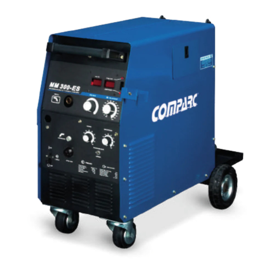
- Page 1 PM1379 REV. 0 E. 12-08-2021 OWNER´S MANUAL MM 300 - ES DC ARC WELDING POWER SOURCE WIRE FEEDER PROCESSES MIG (GMAW). DESCRIPTION CONSTANT VOLTAGE (CV). DC TYPE OUTPUT. SINGLE PHASE. GIVE THIS MANUALTO THE OPERATOR OWNER´S MANUAL 302-589...
-
Page 2: Table Of Contents
TABLE OF CONTENTS ARC WELDING SAFETY PRECAUTIONS ................. i SECTION 1 -- SAFETY SIGNALS AND WORDS ..............1 SECTION 2 -- SPECIFICATIONS ..................... 1 SECTION 3 -- INSTALLATION ....................3 SECTION 4 -- FUNCTION OF CONTROLS ................7 SECTION 5 -- MAINTENANCE & TROUBLESHOOTING............10 SECTION 6 -- ELECTRICAL DIAGRAM................. - Page 3 SAFETY PRECAUTIONS - READ BEFORE USING ARC WELDING can be hazardous. WARNING - DANGER! - Indicates a hazardous situation which, if not avoided, will result in death or serious injury. The possible hazards are shown in the adjoining symbols or explained in the text - Indicates a hazardous situation which, if not avoided, could result in death or serious injury.
- Page 4 WELDING can cause fire or explosion. 4.- Be alert that welding sparks and hot materials from welding can easily go through small cracks and openings to adjacent areas. 5.- Watch for fire, and keep a fire extinguisher nearby. Sparks and spatter fly off from the welding arc. The flying 6.- Be aware that welding on a ceiling, floor, bulkhead, or partition can sparks and hot metal, weld spatter, hot workpiece, and cause fire on the hidden side.
- Page 5 ST EAM AND PRESSURIZED HOT 1.- Do not remove radiator cap when engine is hot. Allow engine to cool. COOLANT can burn face, eyes, and skin. 2.- Wear gloves and put a rag over cap area when removing cap. The coolant in the radiator can be very hot and under 3.- Allow pressure to escape before completely removing cap.
-
Page 6: Section 1 -- Safety Signals And Words
SECTION 1 SAFETY SIGNALS AND WORDS The following safety alert symbol and signal words are used throughout this manual to call attention to and identify different levels of hazard and special instructions. WARNING statements identify procedures or practices which must be followed to WARNING avoid seriuos personal injury or loss of life. - Page 7 2-2 DUTY CYCLE. CAUTION WELDING LONGER THAN RATED DUTY CYCLE can damage unit and void warranty. Do not weld at rated load longer than shown below. 60% Duty Cycle At 250 Amperes Definition Duty Cycle is percentage of 10 minutes that unit or gun can weld at rated load without overheating.
-
Page 8: Section 3 Installation
SECTION 3 INSTALLATION 3-1. GUN INSTALLATION 1 MIG GUN OPENING. 2 TRIGGER RECEPTACLE. 3 WIRE FEEDER MECHANISM. 4 LOCKING KNOB. 5 GUN END. Loosen locking knob and insert gun end through access hole into gun adapter. Tighten locking knob. 6 GUN TRIGGER PLUG. Insert plug into receptacle, and tighten threated collar. - Page 9 3-3 ELECTRICAL SERVICE GUIDE Input Voltage 22.5 Input Amperes (A) At Rated Output Max Recommended Standard Fuse Rating In Amperes 1 Time-Delay Fuses 2 Normal Operating Fuses 3 Min Input Conductor Size In AWG 4 Max Recommended Input Conductor Length In Feet (Meters) (39) (63) Min Grounding Conductor Size In AWG 4...
- Page 10 3-5 WIRE WELDING INSTALLATION. 1.- WIRE SPOOL / REEL. 2.- WELDING WIRE. 3.- GUN END. 4.- PRESSURE ADJUSTMENT KNOB. 5.- DRIVE ROLL. 6.- INLET WIRE GUIDE. 7.- GUN CONDUIT CABLE. Try to keep straight gun conduit when you going to install welding wire. Hold Wire Tightly to Keep It From Unraveling.
- Page 11 3-6 SHIELDED GAS CONNECTIONS. WARNING SEE SAFETY SIGNAL AT THE BEGINING THIS M ANUAL Obtain gas cylinder and chain to running gear, wall, or other stationary support so cylinder can not fall and break off valve. 1.- CAP. 2.- CYLINDER VALVE. Remove cap, stand to side of valve, and open valve slightly.
-
Page 12: Section 4 -- Function Of Controls
SECTION FUNCTION OF CONTROLS SEE SAFETY SIGNAL AT THE BEGINING CAUTION THIS M ANUAL 1- Insulating Gloves. 2- Safety Glasses With Side Shields. 3- Welding Helmet. Wear dry insulating gloves, safety glasses with side shields, and a welding helmet with a correct shade of filter (see ANSI Z49.1). FIGURE 4-1 SAFETY EQUIPMENT. - Page 13 GUN TRIGGER Gun Connector. Connect gun into gun receptacle until bottom and be sure be perfectly tighten. FIGURE 4-4 GUN CONNECTOR. RC14 RECEPTACLE. This connector is a receptacle for a gun spool. To connect this receptacle, align keyway, insert plug, and tighten threaded collar. Socket Information: SOCKET A: 24 Volts AC, 10 Amperes, 60 Hz., respect G socket (common).
- Page 14 DIGITAL METERS DIGITAL VOLTMETER When the trigger of the gun is not activated the preset voltage value (Preset) is displayed. When the trigger of the gun is activated, the real voltage value that exists between the output terminals of the machine is shown, which depending on the situation, can open circuit, arc voltage or short circuit AMPERMETER / DIGITAL SPEEDMETER This meter has two functions to select by means of the switch located on the right of it:...
-
Page 15: Section 5 -- Maintenance & Troubleshooting
Install & Turn On Unit And Readjust Adjust Put On Personal Do a Weld Connect supply gas Controls And Controls Safety Equipment Test Equipment (If Applicable) begin welding FIGURE 4-12 SECUENCE FOR SOLID WIRE AND FLUX CORED ARC WELDING. Install & Connect Adjust hub Adjust drive roll Turn on... - Page 16 5-3. OVERLOAD PROTECTION. Disconnect the unit from the power supply before removing the left side cover. 1.- Left cover. 2.- Fuse F4. 3.- Fuse F5. If fuses F4 and F5 are open, there will be no energy in the fan motor. 4.- Fuse F6.
- Page 17 5-4 TROUBLESHOOTINGS. Table 5-1. Welding Trouble TROUBLE RECOMENDED ACTION Secure power cord plug in receptacle. No weld output; wire does not feed; fan Replace building line fuse or reset circuit breaker if open. does not run. Secure gun trigger plug in receptacle. Power switch in On position.
-
Page 18: Section 6. Electrical Diagram
SECTION 6. ELECTRICAL DIAGRAM POSITIVE SCR1 33 Vac NEGATIVE 230 a c V . . THERMAL PROTECTION OF RECTIFIER 33 Vac SCR2 NOT : E MEANING “T WISTED " S1-A HDR 2x3P RC4-7 T ERMOST RC2-3 THERMAL P. RC4-5 RC1-1 VOLTS/AMPER METER RC2-1 DIGITAL... -
Page 19: Section 7 -- Parts List
SECTIÓN 7. PARTS LIST Ref. Part No. I.D. Description Quantity PC1802 Chasis. Front assembly (fig. 7-2) PR0815 Main rectifier. Consisting of: MT08386 SCR1, 2 Tyristor PR0587 Wheel, rear assembly. PT3684 Transformer, main assembly. Consisting of: PB2412 Coil PC1807 Head core PN0161 Core MT08939... - Page 20 FIGURE 7-1 MAIN ASSEMBLY. P M 13 7 9...
- Page 21 Ref. Part No. I.D. Description Quantity PF0955 Front panel PP4656 Nameplate, upper PP4655 Nameplate, lower Handle assembly. Consisting of: MS03936 Handle support MT08195 Handle MI01178 Switch 15A 1P 1T MP08416 Knob MI00110 Switch 1P1T. PT1826 PC voltmeter/ammeter MP02512 R1, 2 Potentiometer 10KOhms, 2W MP03020 R3, 4...
- Page 22 IT. No PART No. DESCRIPTION QUANTITY PB2303 Feed plate with groove MB06011R Arm compl (With central gear) MF02408R Shaft MB06013R Wire pressure knob ME02417R Drive gear ----- Roll (Ask to your distributor) MM04283 Inlet guide tube PP4429 Fix knob (Gun loking tab) MT08685R Fix bolt PS2098...
- Page 23 NOTES...
- Page 24 NOTES...
- Page 25 WARRANTY POLICY 2°.- SOLDADORAS INDUSTRIALES INFRA S.A. DE C.V. warranty UNIFORM WARRANTY FOR SIISA MACHINES. will be F.O.B. Factory at Naucalpan México, or F.O.B. at an authorized service facility as determined by manufacturer. Therefore no compensation SOLDADORAS INDUSTRIALES INFRA, S.A. DE C.V. (SIISA), or reimbursement for transportation costs of any kind will be allowed.
- Page 26 NOTES...
- Page 27 SERVICE CENTER MAP CANADA LTD 325 Healey Road, Unit 1, Bolton, ON L7E 5C1 Canada Phone: (905) 951-2788 Toll Free: (800) 757-4445 Fax: (905) 951-6256...
Need help?
Do you have a question about the MM 300-ES and is the answer not in the manual?
Questions and answers