Advertisement
Quick Links
The JA-110N-DIN Bus PG-DIN power output module
The JA-110N-DIN is a component of the JABLOTRON 100
system. It provides a PG output power relay switch. It has been
designed for mounting on a DIN rail and for switching mains-
powered output devices (up to 230V /16A). The module should
be installed by a trained technician with a valid certificate issued by
an authorized distributor.
Installation
The module has been designed for mounting on a DIN rail in
conformity with EN60715. It is connected to a system bus through
which it is also powered. It has to be enrolled into the system and
occupies one position.
When connecting the module to the system
digital bus, always switch the power off.
If the module is installed outside the guarded
area, the JA-110T bus insulator should be used
for the external section of the wiring.
Electrical devices can only be connected
by a trained technician.
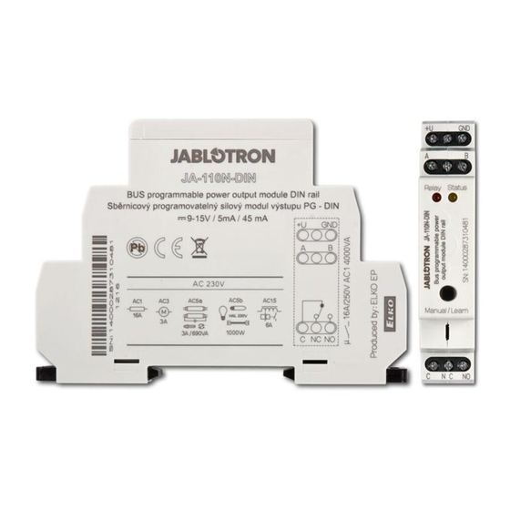
Figure: 1 = bus terminals (CC-01(02) cable): +U red, GND black, A yellow,
B green); 2 = red LED – relay triggering; 3 = yellow LED - failure;
4 = production code; 5 = enrollment or manual trigger button;
6 = relay terminal;
Install the module on a DIN rail.
1.
Connect bus wires to the terminals (1). We recommend using
2.
a CC–01 or CC–02 cable (supplied by Jablotron) to connect
a module.
Proceed according to the control panel installation manual. Basic
3.
procedure:
a. When the relay is switched on, the yellow LED (3) starts
flashing repeatedly to indicate that it has not been enrolled
to the system.
b.
Go to the F-Link program, select the required position in the
Devices tab and launch the enrollment mode by clicking
on the Assign option.
c.
Press the Manual/Learn (enrollment) button (5) – the module
is thus enrolled into the system and the yellow LED goes off.
4. Test the module functioning. When the module is switched on,
the red LED (2) starts to light.
5. Connect the device to be controlled by the relay to the relay
output terminals (6).
The JA-110N-DIN Bus PG-DIN power output module
Setting of module properties
Go to the Detectors window in the F-Link program. When you
are at the module position, use the Internal settings option. Set
the following in the dialogue window:
Manual control (5): Module control with the button is enabled
as a default. Function: brief pressing of the button triggers the relay
(status) ON/OFF. System control commands (on the bus) override
the state selected with the button. Manual control is possible even
in a situation when there is no communication with the control panel
for some reason. The button control function can be completely
disabled in a dialog window.
Relay activation by a PG output: It is possible to select module
activation by one or more PG outputs.
Notes:
Multiple modules can be enrolled to the system. The number
of modules is only limited by the number of devices and by the
power consumption from the digital bus.
If communication is lost (A-B bus connections) for more than
60s, the module relay switches to idle mode.
The module can also be enrolled into the system by entering its
production code (4) in the F-Link program. All numbers should be
entered (number format example: 1400-00-0000-0001).
The settings can also be set in the F-Link - PG outputs tab –
Activation button
Technical specifications
Power
from control panel digital bus 12 V (9...15 V)
Consumption in standby mode (relay off / on)
Current consumption for cable selection
Relay contact capacity (galvanically separated from the bus)
– class protection II:
Maximum acceptable output through voltage 250 V AC / 24 V DC
Halogen lighting
Minimum DC switched power
Minimum DC output power
Connected wire diameter
Dimensions
Environment
Operating temperature range
Degree of protection
Also complies with
JABLOTRON ALARMS a.s. hereby declares that the JA-110N-DIN
is in compliance with the essential requirements and other relevant
provisions of Directives 2006/95/EC and 2004/108/EC. The original
of the conformity assessment can be found at
Technical Support section
Note: Although this product does not contain any harmful
materials we suggest you return the product to the dealer or
directly to the producer after use. For more detailed information
visit www.jablotron.com.
1 / 1
5 mA /45 mA
45 mA
max.16 A
max. 8 A
max. 1000 W
384 W
0.5 W
2
max. 2x 1.5 mm
2
max. 1x 2.5 mm
18 x 90 x 64 mm
indoor general
-15 to +50 °C
IP-20
EN 50130-4, EN 55022,
EN 60950-1, DIN rail EN60715
www.jablotron.com
-
MLY51802
Advertisement


Need help?
Do you have a question about the JA-110N-DIN and is the answer not in the manual?
Questions and answers