Advertisement
Table of Contents
JA-110N Bus power output module PG
The JA-110N is a component of the JABLOTRON 100 system.
It provides an output power relay switch. It can be used for
switching on/off the lights, ventilators, etc. The relay can be
controlled with a programmable control panel (PG) output or
according to the status of a section (armed = relay on) or when
there is an alarm in a chosen section (alarm = relay on). The device
should be installed by a trained technician with a valid certificate
issued by an authorized distributor.
Installation
The module shall be installed into the JA-190PL mounting box.
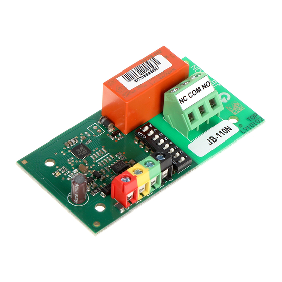
figure: 1 – digital bus terminals; 2 – red relay switching indicator;
3 – configuration switch; 4 – output relay; 5 – relay terminals
1.
Use the switch (3) to set the required number of the PG output or
the number of the section to which the relay should react (see
tables).
Connect bus wires to the terminals (1).
2.
When connecting the module to the
system digital bus, always switch the
power off.
If the module is installed outside the
protected area, the JA-110T bus insulator
should be used for the external section of
the wiring.
Electrical devices can only be
connected by an authorized
technician.
Switch on the system and test its functioning.
3.
4.
Check the supply voltage at the bus terminals (red, black) when
the relay is activated. The voltage must be at least 9V.
5. Connect the controlled device to the relay output terminals (5).
Notes:
- The module does not occupy any position in the control panel
(it is not enrolled into the system).
- If you connect multiple modules with identical settings to the bus,
the relays will have the same function.
- The number of modules is only limited by the power consumption
from the digital bus.
-
The setting of individual programmable
outputs window in the F-Link program. A detailed description of
the setting is available in the control panel installation manual.
- When the output is set according to the SECTION SET table the
relay is on if the section is fully armed.
- When the output is set according to the SECTION ALARM table
the relay is on if there is external or internal warning (EW or IW).
JA-110N Bus power output module PG
outputs is done in the PG
1 / 1
Table 1: The relay reacts to the PG output state
Table 2: The relay reacts to arming
the choosen section
Technical specifications
Power
from control panel digital bus 12 V (9...15 V)
Current consumption in standby mode (relay off / on) 5 mA / 45 mA
Current consumption for cable choice
Relay contact rating
Maximum voltage
Re
I
Minimum acceptable relay output through-wattage(DC)
Protection
Dimensions
Classification
according to
Operational environment according to EN 50131-1
Operating temperature range
Also complies with
JABLOTRON ALARMS a.s. hereby declares that the JA-110N
module is in compliance with the essential requirements and other
relevant provisions of Directive 2004/108/(EC and 2006/95/EC.
The original of the conformity assessment can be found at
www.jablotron.com - Technical Support section
Note: Although this product does not contain any harmful
materials we suggest you return the product to the dealer or
directly to the producer after use. For more detailed information
visit www.jablotron.com.
Table 2: The relay reacts to an
alarm in the choosen section
45 mA
250 V AC / DC
max. 16 A / 250 V AC
max. 8 A / 250 V AC
0.5 W
Class II
78 x 40 x 20 mm
Grade II
EN 50131-1, EN 50131-3
II. Indoor general
°C
-10
to 40
EN 50130-4, EN 55022, EN 60950-1
MLY51306
°C
Advertisement
Table of Contents


Need help?
Do you have a question about the JA-110N and is the answer not in the manual?
Questions and answers