Advertisement
Quick Links
Directions for equalizing the solar panel using the
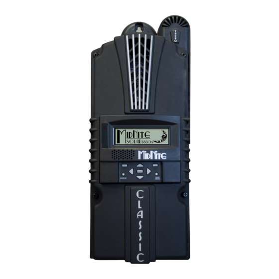
MIDNITE Solar Classic 150 Charge Controller
1. Check programmed absorb, equalize, and float voltages
Note: These values should already be set to the correct values
according to the manual
1. Repeat presses of the "Main Menu" until "Charge" is highlighted
2. Press "Enter"
3. Highlight "Volts"
4. Press "Enter"
5. Make sure the Equalize, Absorb, and Float voltages are 30.6 V, 29.2 V, and
27.0 V respectively.
6. If the voltages do not match up, highlight the values and adjust them
accordingly using the up and down arrow keys.
7. Press "Enter" to save the values
8. Press "Status" to return to the home screen
2. Check programmed equalization time
1. Repeat presses of the "Main Menu" until "Charge" is highlighted
2. Press "Enter"
3. Scroll to the right and highlight "ChgTime"
4. Press "Enter"
Figure A.1: Programmed Voltage Settings
49
Advertisement

Related Manuals for MidNite Solar Classic 150


Summary of Contents for MidNite Solar Classic 150
- Page 1 Directions for equalizing the solar panel using the MIDNITE Solar Classic 150 Charge Controller 1. Check programmed absorb, equalize, and float voltages Note: These values should already be set to the correct values according to the manual 1. Repeat presses of the “Main Menu” until “Charge” is highlighted 2.
- Page 2 5. Make sure the time under “EQ” is 2:00, indicating the equalizing process will be two hours long Figure A.2: Equalization Time 6. If the programmed time is not two hours, scroll to the right and highlight the time under “EQ” 7.
- Page 3 2. Turn off the circuit breaker for the kitchen freezer and the kitchen lights inside the breaker box next to the kitchen door Figure A.4: Kitchen Freezer and Lights Circuit Breakers 3. Turn off the circuit breakers for the solar panel and the charge controller connections inside the breaker box next to the power inverter Figure A.5: Solar Panel Circuit Breaker...
- Page 4 4. Start manual equalization 1. Repeat presses of the “Main Menu” until “Charge” is highlighted 2. Press “Enter” 3. Scroll down and highlight “EQ” 4. Press “Enter” 5. “EQ Stopped” will be highlighted 6. Scroll up to select “EQ Started” 7.
-
Page 5: Turning The Inverter On And Off
Operation manual for the PROwatt SW 1000 Sine Wave Inverter Figure A.7: User Interface 1. Turning the inverter on and off 1. Press the power switch button for half a second to turn on the inverter 2. Press the power switch button for one second to turn off the inverter 3. - Page 6 1. Under normal operating conditions, the green LED is on and the digital display shows the input voltage (volts) and the outpower (kilowatts) 2. Under error or alarm conditions, the digital display shows an error code and the red LED turns on Description of LED and Digital Display Codes Digital Display Description...
- Page 7 Figure A.8: Power Inverter GFCI Outlet 4. Ground Fault Circuit Interrupter (GFCI) Outlet Testing 1. Turn on the power inverter 2. Plug a device, such as a lamp, into the AC outlet 3. Push the Test button • The reset button should pop out and the power should turn off. For example, if the lamp goes out, it is functioning correctly.
- Page 8 Figure A.9: Power Inverter DC Terminals...
- Page 9 Troubleshooting Reference for the PROwatt SW 1000 Sine Wave Inverter Troubleshooting Reference Condition Possible Cause Solution Recharge battery and check Under voltage shutdown connections E01 with persistent low Poor DC wiring/ battery Use proper and secure wiring; battery alarm condition charge or install new battery Check if connected to 12 V Over voltage shutdown...
- Page 10 Operation manual for the JW-MPPT 2.0 high-end wind solar hybrid charge controller Figure A.10: Charge Controller User Interface 1. Shown battery voltage (should be around 12 Volts) 2. Indicates time of day (should have no influence on functionality) 3. Digital display of the battery voltage 4.
-
Page 11: Maintenance
6. Load icon, there will be lighting effects in the bulb when there is an output to the load 7. Charge LED (refer to the table below) 8. Output LED (refer to the table below) 9. Button interface • Enter: Press this button to enter setup interface or switch between programs •... - Page 12 Figure A.12: Under Voltage Reference 6. Ensure that the over voltage is around 15.0 volts Figure A.13: Over Voltage Reference...
Need help?
Do you have a question about the Solar Classic 150 and is the answer not in the manual?
Questions and answers