
Related Manuals for BSC SRV300


Summary of Contents for BSC SRV300
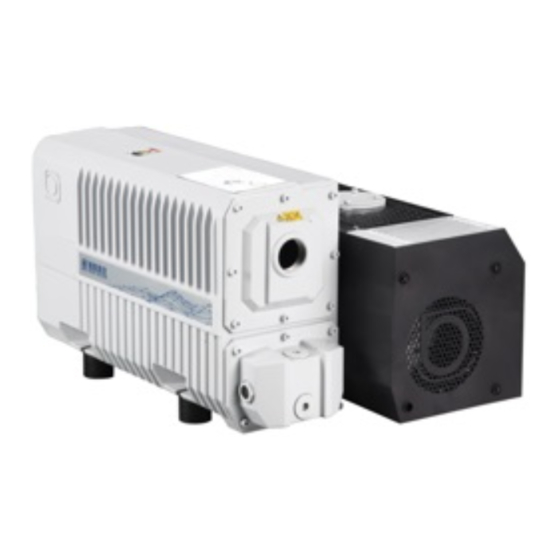
- Page 1 VERSION:1.0 Instruction Manual Single-stage oil-sealed rotary vane vacuum pump SRV300...
-
Page 2: Table Of Contents
Content 1 Introduction……………………………………………………………………………………………………………………………………1 2 Design and function………………………………………………………………………………………………………………………3 3 Application……………………………………………………………………………………………………………………………………4 4 Technical data…………………………………………………………………………………………………………………………………4 5 Installation diagram…………………………………………………………………………………………………………………………5 6 Installation and Operation 6.1 Installation………………………………………………………………………………………………………………………………6 6.2 Inlet side…………………………………………………………………………………………………………………………………6 6.3 Outlet side………………………………………………………………………………………………………………………………7 6.4 Oil filling…………………………………………………………………………………………………………………………………8 6.5 Electric connection…………………………………………………………………………………………………………………8 6.6 Startup……………………………………………………………………………………………………………………………………9 6.7 Operation………………………………………………………………………………………………………………………………9 6.7.1 Pumping of Non-condensable Gases……………………………………………………………………………………9 6.7.2 Pumping of Condensable Gases and Vapors…………………………………………………………………………9 6.7.3 Cyclic process ………………………………………………………………………………………………………………………10 6.8 Stop ……………………………………………………………………………………………………………………………………11... -
Page 3: Introduction
This instruction provides installation, operation, and maintenance instructions for the rotary vane vacuum pump SRV300. In order for you to use this product safely and effectively, please read it carefully and strictly follow the instructions in the manual. SRV300 is hereinafter referred to as pump. - Page 4 ★ The surface temperature of the pump during operation can be as high as 80 ° C. There is a danger of burns when touching the pump. When the pump is running or just stopped, the temperature is still high, please do not touch the motor and the pump and the pump piping to avoid burns.
-
Page 5: Design And Function
2 Design and function The SRV300 is single-stage, oil-sealed rotary vane pump. The anti-suck back valve, gas ballast valve, exhaust filter, oil return circuit and oil cooling oil are integrated functional elements. The pump is driven by a directly flanged motor. -
Page 6: Application
3 Application SRV300 pumps are designed for pumping of inert gases in the range of rough vacuum, between atmospheric pressure and ultimate pressure of the pump. Pumps are not designed for pumping of aggressive, corrosive, flammable or explosive gases. -
Page 7: Installation Diagram
5 Installation diagram... -
Page 8: Installation And Operation
6 Installation and Operation 6.1 Installation It is essential to observe the following instructions step by step to ensure a safe start-up. Start-up may only be conducted by trained specialists. The pump can be set up on any flat, horizontal surface. Under the four feet, there are metric threaded holes for securing the pump. -
Page 9: Outlet Side
6.3 Outlet side The pump have integrated exhaust filters which, even at a high gas throughput, trap the oil mist and guarantee exhaust gas free of oil mist. If the exhaust filters are clogged, pressure relief valve opens and the filters are bypassed. As a result, the proportion of oil in the exhaust gas as well as the pump’s oil consumption rises. -
Page 10: Oil Filling
6.4 Oil filling The pump should use BAOSI vacuum pump oil. For the first refueling, please add to about 10mm above the center of the oil level window. After the pump is running, the oil level will drop. The pump oil level during operation must always be in the middle of the oil-level glass. -
Page 11: Startup
6.6 Start-up Before switching on, always make sure that the pump contains enough oil. The normal oil level is in the middle of sight glass. If oil has to be added, unscrew the oil-fill plug, add oil and screw the plug firmly back in. To avoid overloading the motor, do not start the pump more than six times within one hour. -
Page 12: Cyclic Process
6.7.2 Pumping of Condensable Gases and Vapors. Using gas ballast. With the gas ballast valve open and at operating temperature, the pump pure water vapor up to the water vapor tolerance indicated in the Technical Data. The pump’s water vapor tolerance can be increased by raising the operating temperature. If open the gas ballast valve. -
Page 13: Stop
Stop Under normal circumstances, everything you need to do is to stop the pump. The intake port of the pump contains an anti-suck back valve, which closes the intake port when the pump is shut down, thus maintaining the vacuum in the connected system and preventing oil from being sucked back into the system. -
Page 14: Maintenance
7 Maintenance Disconnect the power before disassembling the pump. Make absolutely sure that the pump cannot be accidentally started. If the pump has pumped harmful substances, ascertain the nature of the hazard and take adequate safety measures. Observe all safety regulations. 7.1 Maintenance schedule The frequencies stated in the maintenance schedule are approximate values for normal pump operation. -
Page 15: Checking The Oil
7.2 Checking the Oil 7.2.1 Oil Level The pump oil level during operation must always be in the middle of the oil-level glass. When necessary, switch off the pump and add the correct quantity of oil. High oil consumption often indicates that exhaust filters are clogged Stop the pump to fill oil. -
Page 16: Replacing Oil Filter
7.4 Replacing oil filter 1. Remove the M8 screws on the exhaust port cover。 2. First remove the three filter element springs and W-type filter element holder from the fuel tank, and then pull the three filter elements out of the fuel tank. 3. -
Page 17: Checking The Anti-Suck Back Valve
Checking the Anti-Suck back Valve Keep the anti-suck back valve clean to ensure proper operation of the pump. If the pump is exposed to large amounts of dust or dirt, we strongly recommend installing a dust filter upstream. First disconnect the intake flange. Remove four screws and take off the intake flange and gasket. -
Page 18: Disposal And Store
Disposal and store Check the pump for the presence of any oil leaks, because there is the danger that someone may slip on the oil which has leaked from the pump. Only use the lifting lugs which are provided on the pump to lift the pump with the specified lifting devices. Until the pump is put back into service again, the pump should be stored in a dry place, preferably at room temperature (20 °C) but not below 0°C. -
Page 19: Disclaimer
11 Disclaimer 1. Products beyond the warranty period; 2. Man-made damage or damage caused by irresistible external factors (natural disasters, etc.); 3. Failures and faults caused by using the wrong method not in accordance with the content of the instruction manual; 4. -
Page 20: Troubleshooting
12 Troubleshooting Table.2 Troubleshooting Fault Possible cause Remedy Pump is connected incorrectly Connect the pump correctly Motor protection switch incorrectly Set motor protection switch properly set. Operating voltage does not match Replace the motor motor Pump does Motor is malfunctioning Replace the motor not start Oil temperature is below 12°C (54°F) - Page 21 Ambient temperature is too high Set pump up correctly Process gas is too hot Change the process Oil level is too low Add oil to reach the correct oil level Pump gets Oil is unsuitable Change the oil too hot Oil cycle is obstructed Clean or repair the oil lines Exhaust filter / exhaust line is...
-
Page 22: Check Sheet For Repair
Check Sheet for Repair Model Serial Purchase Date Customers Address Person in charge Tel No. 1 Request item □Scheduled inspection repairing □Trouble Condition:□Ultimate pressure □Unusual sound □Irregular action □Oil leak outside the pump □Others Description of trouble: □Others: 2 Service condition Whether the pump has been used:... - Page 23 Ningbo Baosi Energy Equipment Co.,Ltd Add:No.55, Juchao Road, Jiangkou subdistrict, Fenghua District, Ningbo City, Zhejiang Province, China Post code:315500 Tel:0574-88569588 59516555 Fax:0574-88569596 Email:bsvac@cnbaosi.com Htttp://www.cnbaosi.com...
Need help?
Do you have a question about the SRV300 and is the answer not in the manual?
Questions and answers