Advertisement
Quick Links
OPERATION MANUAL
□
IC-18A INDUCTION COOKER
□
IC-22A INDUCTION COOKER
□
IC-25A INDUCTION COOKER
120V, 60Hz, 1.8KW
208V, 60Hz, 2.2KW
240V, 60Hz, 2.5KW
Cecilware Corporation
43-05 20th Avenue
Long Island City, NY 11105
Tel: 800.935.2211, 718.932.1414
Fax: 718.932.7860
Technical Support
Tech.Support@cecilware.com
Customer Service:
Customer.Service@cecilware.com
www.cecilware.com
Advertisement

Related Manuals for Cecilware IC-18A

Summary of Contents for Cecilware IC-18A
- Page 1 OPERATION MANUAL □ IC-18A INDUCTION COOKER 120V, 60Hz, 1.8KW □ IC-22A INDUCTION COOKER 208V, 60Hz, 2.2KW □ IC-25A INDUCTION COOKER 240V, 60Hz, 2.5KW Cecilware Corporation Long Island City, NY 11105 Tel: 800.935.2211, 718.932.1414 Tech.Support@cecilware.com Customer.Service@cecilware.com www.cecilware.com 43-05 20th Avenue Fax: 718.932.7860...
- Page 2 USE AND CARE INSTRUCTIONS – IMPORTANT SAFEGUARDS READ ALL INSTRUCTIONS BEFORE OPERATING Use a dedicated electrical circuit. IC-18A: 120V IC-22A: 208V IC-25A: 240V DO NOT block the air-intake panel. Blocking may overheat the unit. Use pans 4.75” (12cm) or larger in diameter. We recommend that pans be less than 10” (26cm) in diameter.
-
Page 3: Safety Devices
SUITABLE POTS & PANS, - FOR INDUCTION HEATING PLATES 1. Iron 2. Cast iron 3. Stainless steel***** 4. Enamelware *****All pots and pans must have a magnetic bottom.***** All pots and pans must have a flat bottom. All pots and pans should have a diameter between 4.75” (12 cm) and 10.25” (26 cm). UNSUITABLE POTS &... - Page 4 8. Immediate clean up is recommended when water is left on the top plate. OPERATION INSTRUCTION 1. Plug power cord into 120V, 60Hz, 15A (IC-18A); 208V, 60Hz, 11A (IC-22A); 240V, 60Hz, 11A (IC-25A) dedicated electrical circuit. 2. Turn power on by pressing the power on/off button.
- Page 5 Temperature Hold function: By pressing the “Warm” function key, the Temperature Hold function will start working. The LED indicates the temperature will hold at 140°F “Warm” function key again, the LED indicates the temperature will hold at 180°F. When the “Warm”...
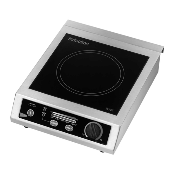
- Page 6 FEATURES & DESCRIPTION: 1. Induction Heating Zone 2. Ceramic Top Plate 3. Bottom Chassis 4. Rotary Control Knob (Power Regulator) 5. Induction Heating Indicator Light 6. Heat Function Indicator Light 7. “Warm” Function Indicator Light 8. Air-Intake 9. Air-Outlet 10. Foot Stand...
-
Page 7: Specification
3. The “Wall Stopper” functions as a “Stand-off”, allows the exhaust fan, built into the unit, to operate properly. Improper mounting or removal of this piece will cause the unit to operate improperly and possibly overheat. SPECIFICATION: Model No. IC-18A 120V ~ 60Hz Voltage Vitro-Ceramic Glass Plate Electrical Power Max. -
Page 11: Troubleshooting
Pan isn’t located in the center properly Pan is smaller than 2” Over-heating protection is activated High temperature Air entrance or outlet blocked Over-heating protection activated Cecilware Corporation 43-05 20th Avenue Long Island City, NY 11105 Tel: 800.935.2211, 718.932.1414 Fax: 718.932.7860 Technical Support Tech.Support@cecilware.com...
Need help?
Do you have a question about the IC-18A and is the answer not in the manual?
Questions and answers