Table of Contents
Advertisement
Quick Links
Advertisement
Table of Contents

Related Manuals for AQUANTIS MICROFREEZE


Summary of Contents for AQUANTIS MICROFREEZE
- Page 1 MICROFREEZE® USER’S GUIDE Document No: MICROFREEZE2019-1 April 2019...
- Page 2 Aquantis S.A. Aquantis Belgium B.V.B.A. EPFL Innovation Park Bâtiment C Generaal De Wittelaan 17C CH-1015 Lausanne B-2800 Mechelen Switzerland Belgium Tel: +41 79 159 97 25 Tel: +32 15 68 24 21 E-mail : info@aquantis.org Website : www.aquantis.org Microfreeze User’s Guide...
-
Page 3: Table Of Contents
Description of operation ......................... 14 7.3.3 Display ............................. 14 7.3.4 Webserver interface ........................17 7.3.5 Modbus TCP/IP interface ........................ 32 Maintenance & Disposal ..........................33 Daily maintenance ..........................33 Yearly maintenance ..........................33 Disposal..............................33 Troubleshooting ............................34 Microfreeze User’s Guide... - Page 4 Electrical specifications ........................35 10.2.1 High frequency electronics – GHz Technology................35 10.2.2 Low frequency electronics ......................35 10.3 Mechanical specifications ........................36 10.3.1 Materials ............................. 36 10.3.2 Computer-box ..........................36 10.3.3 HF measurement units ........................ 37 Microfreeze User’s Guide...
-
Page 5: About The User Guide
2 About the user guide Introduction The Microfreeze is intended to determine the level-of-frozenness (LOF) of your food products. This device is developed and manufactured by Aquantis. The product number is indicated on the device and has the format: AQMF-XXX-XX-2019-X. Please provide the product number during every communication with Aquantis. -
Page 6: Disclaimer
3 Disclaimer In no respect shall Aquantis incur any liability for any damages, including, but limited to, direct, indirect, special, or consequential damages arising out of, resulting from, or any way connected to the use of the sensor, whether or not based upon warranty, contract, tort, or otherwise;... -
Page 7: Safety Information
If you use an extension power cable, ensure that the total ampere rating of the products plugged in to the extension power cable does not exceed the ampere rating of the extension cable. WARNING: The customer is responsible to connect all metal parts of the Microfreeze to protective earth via a low resistive path (< 1 Ohm). -
Page 8: Transport And Storage
• Storage temperature: between –40 and +50 °C • Relative humidity: max. 95%, non-condensing • For storage periods of longer than 3 months, check the general condition of the individual units and packaging on a regular basis. Microfreeze User’s Guide... -
Page 9: Sensor Installation And Integration
WARNING: The customer is responsible to connect all metal parts of the system to protective earth via a low resistive path (< 1 Ohm). Aquantis is not responsible for any damage or dysregulation of the system and other equipment due to no or a bad connection to earth. - Page 10 ✓ Make sure there is no electromagnetic coupling from other devices operating in the same HF frequency range: 2.4-2.5 GHz and 5.725-5.875 GHz. Respect a distance of 1 m from the MICROFREEZE system. Microfreeze User’s Guide...
-
Page 11: Power Supply Cables
INAPPROPRIATE POSITIONING OF THE DISTANCE WHICH RESULTS IN WRONG MEASUREMENTS Power supply cables The Microfreeze is powered via the computer unit which further distributes the power to the distance sensor, emitter and receiver units. Figure 4 shows the incoming power (red) and the distribution links (blue). Please connect the main power to a single 230 VAC –... -
Page 12: Data Interconnection
7.1.1 Power on The Microfreeze is switched on by plugging the power cord in a socket or by supplying the power via the PLC system. The sensors operating system boots up automatically upon switching on. This start-up phase takes a few minutes. -
Page 13: Connectivity
7.2.1 Connecting to the sensor via a PC The Microfreeze can be directly connected to a PC by means of the Ethernet RJ45 connector. The sensor can then be interfaced via a web browser or dedicated PLC emulation software making use of the MODBUS TCP protocol. -
Page 14: Connecting To The Sensor Via The Network Infrastructure
7.2.2 Connecting to the sensor via the network infrastructure The Aquantis sensor can be connected to the network infrastructure to access it from a distance, e.g. by means of a PLC. The sensor is equipped with a DHCP client to negotiate an IP address within the network domain. -
Page 15: User Interface
User Interface 7.3.1 Introduction The Aquantis Free-space freezing sensor can be interfaced in different ways: ✓ Display (read only) ✓ Webserver interface (read & write) ✓ Modbus TCP/IP (read & write) In what follows, the different user interfaces are further explained. - Page 16 - Wrong product selection or database parameters - Multiple products are stacked on top of each other - Thickness sensor needs calibration – execute the thickness calibration wizard 8: LCD- IGURE DISPLAY START UP SCREEN Microfreeze User’s Guide...
- Page 17 9: LCD- IGURE DISPLAY DATA SCREEN Microfreeze User’s Guide...
-
Page 18: Webserver Interface
LINK TO: Thickness sensor calibration wizard LINK TO: Product specifications / signal processing ▪ LINK TO: Product signal processing wizard ▪ SETTINGS [password protected – read/write] ▪ LOGGING CENTER [password protected – read/write] ▪ ABOUT [freely accessible - read only] ▪ SHUTDOWN Microfreeze User’s Guide... - Page 19 IGURE ASHBOARD WEBPAGE The home-page of the MICROFREEZE sensor consist of a freely accessible dashboard (Figure 10) on which the following parameters of the sensor are published: 1. PRODUCT SELECTION: shows the active product together with its product label as specified in the product database.
- Page 20 3. CURRENT DATE AND TIME: shows the real-time clock of the MICROFREEZE sensor. 4. LEVEL-OF-FROZENNESS GAUGE: ▪ static mode: real-time LOF value (%). ▪ dynamic mode: product-averaged LOF value (%) (only products accepted for measurement). 5. PRODUCT THICKNESS GAUGE: ▪...
- Page 21 LOF chart data by resetting all data to 0. 7.3.4.3 Control centre Protection level: password protected. To get access to the control centre page, the user will be prompted for a username and password. The standard login is: username: “admin” password: “aquantis” Microfreeze User’s Guide...
- Page 22 The first and the second reference object should be, respectively, thicker and thinner that the product thickness on the production line. The calibration procedure is initiated by selecting the appropriate sensor configuration: products on conveyor or products in free-fall. Microfreeze User’s Guide...
- Page 23 Next, the exact thickness of the reference object needs to be provided in mm with a precision of 1 digit after the comma. The same procedure is repeated for the second reference object (see Figure 14 - Figure 16). 14: T IGURE HICKNESS SENSOR CALIBRATION WIZARD THICKNESS INPUT OF REFERENCE Microfreeze User’s Guide...
- Page 24 15: T IGURE HICKNESS SENSOR CALIBRATION WIZARD REFERENCE 16: T IGURE HICKNESS SENSOR CALIBRATION WIZARD THICKNESS OF REFERENCE Microfreeze User’s Guide...
- Page 25 5. CHARACERISTIC LATERAL DIMENSION: This parameter, together with the conveyor belt or product velocity, is used to estimate the product interaction time. A tolerance on the expected interaction time is applied to accept or reject products based on the measured interaction time in dynamic mode of operation. Microfreeze User’s Guide...
- Page 26 18: P 2/2. IGURE RODUCT SPECIFICATIONS PAGE PART A second part of the webpage contains the autoconfiguration and visualisation of the settings: 14. AUTOCONFIGURATION WIZARD: See section 7.3.4.6 for more information. Microfreeze User’s Guide...
- Page 27 The auto-configuration wizard starts with an introduction describing the prerequisites that needs to be fulfilled prior to continue with the configuration procedure. This is illustrated in Figure 19 to Figure 24. The configuration procedure is initiated by pressing NEXT. Microfreeze User’s Guide...
- Page 28 The acceptance interval needs to be specified in step 3 of the wizard (see Figure 21). 21: A 3/6. IGURE CONFIGURATION WIZARD ACCEPTANCE INTERVAL STEP In step 4, the averaging intensity needs to be specified. This value is relative to the product size / interaction time. Microfreeze User’s Guide...
- Page 29 FILTER INTENSITY STEP In step 5, the number of products to be averaged for the LOF calculation needs to be specified. 23: A 5/6. IGURE CONFIGURATION WIZARD PRODUCT AVERAGING STEP 24: A 6/6. IGURE CONFIGURATION WIZARD OVERVIEW STEP Microfreeze User’s Guide...
- Page 30 10 min. The file name of every logging file comprises the timestamp at the time of closing the file. The MICROFREEZE has an event logging feature which is always active.
- Page 31 7. Y-AXIS: Set the parameters of the vertical axes with Y1 on the left side and Y2 on the right side on the graph. 8. REFRESH: Refreshes the graph. 9. CLEAR: Clears the graph without removing the current acquisition data. 10. CLEAR ALL: Clears the graph completely including the current acquisition data. Microfreeze User’s Guide...
- Page 32 14. CHART: Chart displaying the data points. 7.3.4.9 About Protection level: freely accessible. The about-page contains basic information about the sensor as well as a download-link to the user-manual. 27: A IGURE BOUT PAGE Microfreeze User’s Guide...
-
Page 33: Modbus Tcp/Ip Interface
0: not valid 1: valid UINT16 Sensor heart beat auto-initialized to 1 at start-up writing 0 to this register results in sensor software shutdown. Keep the sensor power on for at least 2 min after initiating the shutdown process. Microfreeze User’s Guide... -
Page 34: Maintenance & Disposal
8 Maintenance & Disposal Aquantis sensors are designed to provide many years of service in the field. To assure the system performs at its highest accuracy, the sensor should be kept in good conditions. Daily maintenance On a daily base, the antenna caps and laser distance sensor window should be dry and clean to get the best measurement results. -
Page 35: Troubleshooting
Description of the fault which occurred. Repairs Repairs of the sensor are only carried out by Aquantis or Aquantis-certified engineers. Contact Aquantis for the repair of the sensor. Any manipulation or modification of the sensor can result in additional costs. -
Page 36: Technical Data
Remote interaction with the sensor via a browser ▪ DHCP client Automatic negotiation of IP address 10.2.2.3 Data acquisition ▪ Resolution 16 bits ▪ Capacity LOF calculations > 10 LOF values per second (1 LOF per product or batch) Microfreeze User’s Guide... -
Page 37: Mechanical Specifications
EM output cap Polytetrafluoroethylene (PTFE) Fixation Stainless steel spacers M10 Sealing White EPDM flat seals for HF box covers & EM output cap 10.3.2 Computer-box Weight: order of magnitude of 30 kg 28: C IGURE OMPUTER UNIT OUTER DIMENSIONS Microfreeze User’s Guide... -
Page 38: Hf Measurement Units
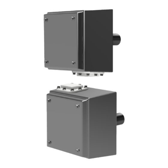
10.3.3 HF measurement units Figure 29 shows the outer dimensions of both the emitter and receiver. Weight per unit: order of magnitude of 5 kg 29: R IGURE ECEIVER UNIT OUTER DIMENSIONS Microfreeze User’s Guide...
Need help?
Do you have a question about the MICROFREEZE and is the answer not in the manual?
Questions and answers