
Related Manuals for MasterCraft 054-6841-4


Summary of Contents for MasterCraft 054-6841-4
- Page 1 ROUTER TABLE 054-6841-4 IMPORTANT: INSTRUCTION Read and understand this instruction manual MANUAL thoroughly before using the product.
- Page 2 headline bars headline bars headline bars continuation tabs continuation tabs continuation tabs notes notes notes warnings warnings warnings...
-
Page 3: Table Of Contents
TABLE OF CONTENTS Technical Specifications Safety Guidelines Key Parts Diagram Operating Instructions Maintenance Troubleshooting Parts List Warranty NOTE: If any parts are missing or damaged, or if you have any questions, please call our toll-free helpline at 1-800-689-9928. SAVE THESE INSTRUCTIONS •... -
Page 4: Technical Specifications
054-6841-4 | contact us 1-800-689-9928 TECHNICAL SPECIFICATIONS Model 054-6841-4 Table size (approximate) 14 1/8" × 23 5/8" Table height 12 1/2" Switch rating 120V 60Hz 15A Cord length continuation tabs continuation tabs... -
Page 5: Safety Guidelines
SAFETY GUIDELINES WARNING! Safety symbols in this Instruction Manual are used to flag possible dangers. The safety symbols and their explanations require your full understanding. The safety warnings do not, by themselves, eliminate any danger, nor are they substitutes for proper accident prevention measures. WARNING! This Safety Alert Symbol indicates caution, warning, or danger. - Page 6 054-6841-4 | contact us 1-800-689-9928 • Keep the work area clean. Cluttered areas and benches invite accidents. • Don’t use in a dangerous environment. Don’t use power tools in damp or wet locations or expose them to rain.
- Page 7 • Never stand on the tool. Serious injury could occur if the tool is tipped or if the cutting tool is contacted unintentionally. • Check damaged parts. Before further use of the tool, a guard or other part that is damaged should be carefully checked to determine whether it will operate properly and perform its intended function.
- Page 8 054-6841-4 | contact us 1-800-689-9928 • This tool is intended for use on a circuit that has an outlet that looks like the one illustrated in Sketch A in the figure below. The tool has a grounding plug that looks like the plug illustrated in sketch A in the figure below.
- Page 9 WARNING! Ensure that the power supply outlet in question is properly grounded. If not sure, have a licensed electrician check the outlet. WARNING! To avoid electrical hazards, fire hazards, or damage to the tool, use proper circuit protection. SPECIFIC SAFETY RULES FOR THE ROUTER TABLE WARNING! Read all instructions.
- Page 10 054-6841-4 | contact us 1-800-689-9928 • Be prepared for the reaction torque of the router, particularly if the cutter bit becomes jammed in the workpiece. • Become familiar with the working area, and be alert for possible hazards that cannot be heard due to the noise of the router.
- Page 11 UNPACKING WARNING! If any parts are missing, DO NOT attempt to assemble, install, or use the router table until the missing parts have been found or replaced and the router table has been properly and correctly assembled according to this Instruction Manual. To simplify handling and to minimize any damage that may occur during shipping, the router table comes partially assembled.
- Page 12 054-6841-4 | contact us 1-800-689-9928 Plain washer Round-head square-neck bolt M6x26 Round-head square-neck bolts M6x35 Round-head square-neck bolt M6x40 continuation tabs continuation tabs continuation tabs continuation tabs...
-
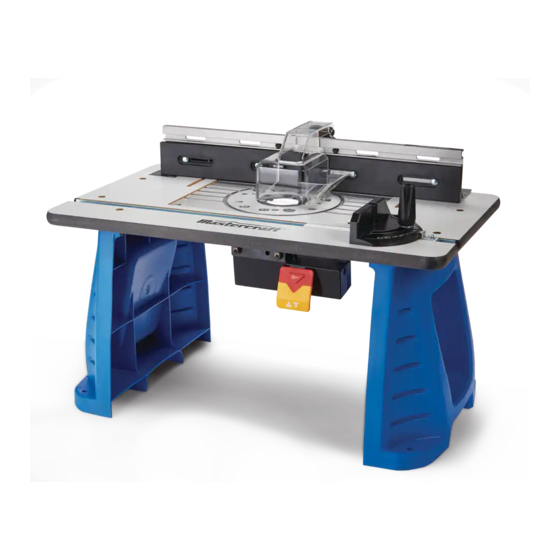
Page 13: Key Parts Diagram
KEY PARTS DIAGRAM Description No. Description Tabletop surface Fastening holes Out-feed fence Mitre-gauge Extended fence Above-table height adjust hole Feather board In-feed fence Integrated safety switch Vacuum adaptor Switch box Dust collection and guard The router table has a precision-built electric switch box, and it should only be connected to a 120V AC, 60Hz power supply (normal household current). -
Page 14: Operating Instructions
054-6841-4 | contact us 1-800-689-9928 ASSEMBLY AND ADJUSTMENT fig 1 ATTACHING THE LEGS TO THE TABLETOP 1. Place the tabletop on a flat, level surface, with the underside of the table facing up. - Page 15 ATTACHING THE ROUTER TO THE ROUTER TABLE (fig 3) The holes on the router mounting plate can fit most popular routers: Mastercraft , MAXIMUM , Bosch ® ® ® Porter Cable , DeWALT , Ryobi ® ® ® fig 3...
- Page 16 054-6841-4 | contact us 1-800-689-9928 ATTACHING THE ROUTER TO THE ROUTER TABLE 1. Unplug the router and the router table. fig 4 2. Remove the plastic sub-base from the router base (fig 4).
- Page 17 ATTACHING THE FENCE TO THE TABLE (fig 7) 1. Place the fence assembly on the tabletop surface, fig 7 and align the two holes on the bottom of the fence assembly with the two slots on the router table. 2. From underneath, slide a long round-head square-neck bolt (10) through the left hole and a round-head square- neck bolt (8) through the right hole.
- Page 18 054-6841-4 | contact us 1-800-689-9928 ATTACHING THE MITRE fig 9 GAUGE (fig 9) 1. The mitre gauge is shipped completely assembled. 2. Attach the mitre gauge to the table by placing the mitre-gauge bar in the slot on the table.
- Page 19 ATTACHING THE FEATHERBOARDS (fig 11) fig 11 ATTACH THE FEATHER BOARD TO THE FENCE 1. Place the feather board on the fence as shown in fig 11. 2. Insert the long round-head square-neck bolt (9) through the holes in the fence and the slot in the feather boards.
- Page 20 054-6841-4 | contact us 1-800-689-9928 ADJUSTING THE FENCE (fig 12-14) fig 12 The fence supports and guides the workpiece. To provide the best support during routing operations, the fence facings should be as close to the bit as possible without contacting the bit (typically about 1/4”...
- Page 21 15 The router table features an access hole to allow use with the over-table height adjustment on the Mastercraft 054-6902-0 router (sold separately). Refer to your router manual for additional information for using this feature. INSTALLING SWITCH BOX ASSEMBLY TO THE TABLETOP (fig 16) 1.
- Page 22 054-6841-4 | contact us 1-800-689-9928 SWITCH BOX OPERATION fig 17a (fig 17a-17c) Safety key Two receptacles are located at the back of the switch assembly. Use one for plugging in the router. The other may be used to plug in a vacuum or a light (not included).
- Page 23 USING A VACUUM The vacuum adaptor in the fence assembly is 2 1/2” (6.4 cm) in diameter. Select the vacuum accordingly. GENERAL ROUTING OPERATIONS WITH THE ROUTER TABLE 1. Read and understand entire Instruction Manual for the router. 2. Always plug the router into the switched outlet in the router table. Never plug a router-table-mounted router into another power source.
- Page 24 054-6841-4 | contact us 1-800-689-9928 ADJUSTING DEPTH AND HEIGHT OF CUT fig 19 Scrap Workpiece (fig 19) Detail 19 1. Unplug the router table. 2. Select a board that is smooth and straight, with good square edges.
- Page 25 USING THE STARTER PIN FOR EDGE fig 20 Starter Pin FORMING OF CURVES (fig 20) Pilot Bearing Bit The starter pin is used for operations that involve routing curves in the workpiece. 1. Turn off the router table switch and unplug the router table.
-
Page 26: Maintenance
054-6841-4 | contact us 1-800-689-9928 BEFORE EACH USE: 1. Inspect the router, the switch, and the cord for damage. 2. Check for damaged, missing, or worn parts. 3. Check for loose screws, misalignment or binding of moving parts, or any other condition that may affect the operation. -
Page 27: Troubleshooting
Problem Possible Causes Solution The router is not plugged into the Plug the power cord from the router router table outlet into the router table outlet The router does not The power cord for the router table Plug the power cord for the router work is not connected to a power source table into a power source... -
Page 28: Parts List
054-6841-4 | contact us 1-800-689-9928 EXPLODED VIEW continuation tabs continuation tabs continuation tabs continuation tabs continuation tabs continuation tabs notes notes notes notes notes notes warnings... - Page 29 Part No. Description Part No. Description 5620369000 Screw 3550846000 Fulcrum Pin 5610023000 Tapping Screw 3123246000 Tabletop Insert 3703940000 Support 5630056000 Wing Nut 2822230000 Switch Box Assembly 5650017000 Plain Washer Prevailing Torque 5630015000 3123929000 Feather Board Hexagon Nut 3123547000 Dust Cover 5640168000 Square Neck Bolt 5640021000 Lock Bolt...
-
Page 30: Warranty
054-6841-4 | contact us 1-800-689-9928 This Mastercraft product is guaranteed for a period of 3 years from the date of original retail purchase against defects in workmanship and materials, except for the following components: a) Component A: Batteries, chargers and carrying case, which are guaranteed for a period of 2 years from the date of original retail purchase against defects in workmanship and materials;... - Page 31 The provisions contained in this warranty are not intended to limit, modify, take away from, disclaim or exclude any statutory warranties set forth in any applicable provincial or federal legislation. Made in China Imported by Mastercraft Canada Toronto, Canada M4S 2B8...
Need help?
Do you have a question about the 054-6841-4 and is the answer not in the manual?
Questions and answers