
Related Manuals for Stryker RemB

Summary of Contents for Stryker RemB
- Page 1 RemB Electric ® Universal Driver 6400-099-000 Instructions For Use ENGLISH (EN) 2018-10 6400-099-700 Rev-AA www.stryker.com...
-
Page 2: Indications For Use
Stryker sales representative or call Stryker customer service. Outside the US, contact your nearest Stryker subsidiary. NOTE: The RemB Electric Universal Driver (handpiece) is also known as the RemB Universal Driver. Indications For Use The Stryker Consolidated Operating Room Equipment (CORE™) - Page 3 • The healthcare professional performing any procedure is responsible for determining the appropriateness of this equipment and the specific technique for each patient. Stryker, as a manufacturer, does not recommend surgical technique. • ALWAYS allow the equipment to reach the specified operation temperature range before use.
- Page 4 NOTES: • Cutting accessories are sterilized using irradiation. • For a complete list of accessories, contact your Stryker sales representative or call Stryker customer service. Outside the US, contact your nearest Stryker subsidiary. The following Stryker-approved accessories are sold separately:...
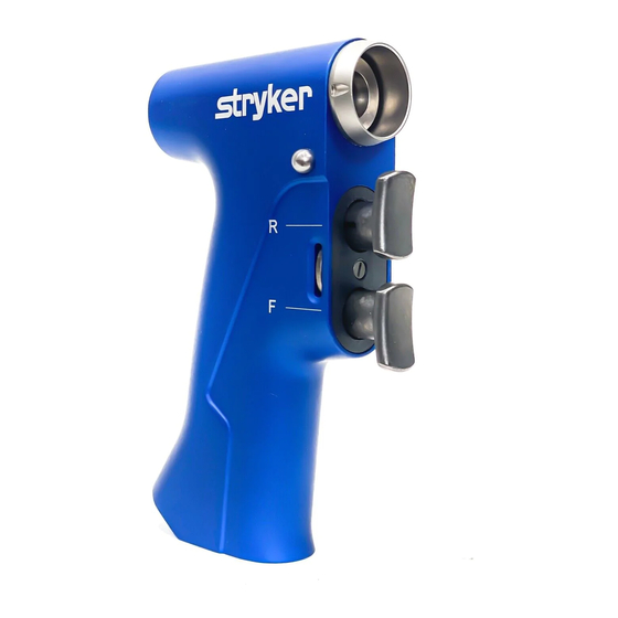
- Page 5 Reverse Trigger – Press this pressure sensitive trigger to obtain variable speed reverse operation. Forward Trigger – Press this pressure sensitive trigger to obtain variable speed forward operation. Cord Receptacle Function Switch – Adjust this switch to the desired function. Functions and switch positions are described below. www.stryker.com...
-
Page 6: Function Switch
The symbols located on the equipment and/or labeling are defined in this section or in the Symbol Definition Chart. See the Symbol Definition Chart supplied with the equipment. SYMBOL DEFINITION REVERSE TRIGGER FORWARD TRIGGER SAFETY FORWARD FORWARD/REVERSE Cord Alignment Mark General warning sign www.stryker.com... - Page 7 To Install an Attachment 1. Vertically align the two J-slots on the attachment with the attachment connector. 2. Insert the attachment into the attachment connector until it snaps into place. 3. Gently tug the attachment to verify the attachment is secure. www.stryker.com...
- Page 8 To Remove an Attachment 1. Fully depress the release button. 2. Firmly grasp and pull the attachment from the attachment connector. Final Disassembly 1. Unplug the cord from the console and from the handpiece. 2. Remove attachment as described above. www.stryker.com...
-
Page 9: Troubleshooting
6400-099-700 Rev-AA Troubleshooting WARNING: DO NOT disassemble or service this equipment without the authorization of the manufacturer. NOTE: For service, contact your Stryker sales representative or call Stryker customer service. Outside the US, contact your nearest Stryker subsidiary. PROBLEM CAUSE... -
Page 10: Care Instructions
Relocate electrical equipment; increase spatial distance. Plug operating room equipment into different operating room outlets. Care Instructions For processing instructions and disposal/recycle information, see the care instructions manual supplied with the equipment. www.stryker.com... -
Page 11: Specifications
Mode of Operation: Non-continuous Operation Duty Cycle: 20 seconds on/20 seconds off, 6 times Rest Between Cycles: 45 minutes Power Supply: Stryker CORE 2, CORE, or TPS Console 40 V (Direct Current) Equipment Type: Type BF Applied Part Maximum Less than 124 °F [51 °C] (Maximum... - Page 12 ES/DE/FR/IT/NL 6400-099-713 JA/ZH/KO 6400-099-720 SV/DA/FI/PT/NO 6400-099-730 PL/EL 6400-099-750 Stryker Instruments 4100 E. Milham Kalamazoo, Michigan (USA) 49001 1-269-323-7700 1-800-253-3210 2018-10 6400-099-700 Rev-AA www.stryker.com...
Need help?
Do you have a question about the RemB and is the answer not in the manual?
Questions and answers