Table of Contents
Advertisement
Quick Links
INSTALLATION AND INSTRUCTION MANUAL
SS670- - - - 013
SS670
SS670
SS670
Installation and Operating Instructions
Installation and Operating Instructions
Installation and Operating Instructions
Installation and Operating Instructions
Due to continuous product improvements, we must reserve the right to change any specifications and information,
contained in this manual at any time without notice. Star Headlight & Lantern Co., Inc. makes no warranty of any
kind with regard to this manual, including, but not limited to, the implied warranties of merchantability and fitness
for a particular purpose. Star Headlight & Lantern Co., Inc. shall not be liable for errors contained herein or for
incidental or consequential damages in connection with the furnishing, performance, or use of this manual.
013
013
013
SIREN
SIREN
SIREN
SIREN
NOTICE
PLITSTR332 REV. D
6/21/21
Advertisement
Table of Contents

Related Manuals for Star Headlight & Lantern SS670


Summary of Contents for Star Headlight & Lantern SS670
- Page 1 INSTALLATION AND INSTRUCTION MANUAL SS670 SS670- - - - 013 SS670 SS670 SIREN SIREN SIREN SIREN Installation and Operating Instructions Installation and Operating Instructions Installation and Operating Instructions Installation and Operating Instructions NOTICE Due to continuous product improvements, we must reserve the right to change any specifications and information, contained in this manual at any time without notice.
-
Page 2: Table Of Contents
Installation Information MODEL: SS670-013 Serial #: PURCHASE DATE: INSTALLATION DATE: INSTALLER: DEALER: Model and serial number located on bottom of unit TABLE OF CONTENTS GENERAL DESCRIPTION INSTALLATION NOTES MOUNTING TIPS ELECTRICAL CONNECTIONS Wiring Guide Wiring Diagram Mandatory Connections Optional Connections... -
Page 3: General Description
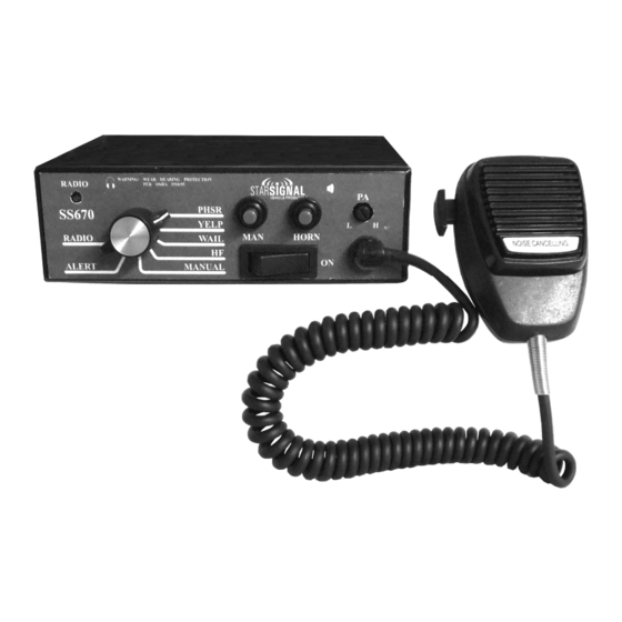
General Description The SS670 Siren Amplifier is a premium 100W unit designed for single 100W speaker use. The primary operating modes are Phaser, Yelp, Wail, Hands Free, Manual, Alert, and Radio. A Noise Canceling PA Override and push-button Horn Override are available in all modes. -
Page 4: Electrical Connections
Electrical Connections Wire Size and Termination Electrical connections to this unit are made through the green 12-terminal connector located in the rear of the unit (See below - Part # CPSS-153). Examine the charts below to determine the proper gauge of the wire to use. Please review the following recommendations when making your electrical connections: ... -
Page 5: Wiring Diagram
(Electrical Connections CONT’D) For ease of installation, you can remove the green connector from the siren while connecting your wires. Please note that when referencing terminal numbers using the wiring diagram on the previous page, the screw heads face UP, as pictured to the right. -
Page 6: Optional Tone Programming
Optional Tone Programming The SS670 will produce 7 different tones/sounds by activating its various functions: Function Default Tone Phaser Step Up Two-Tone (PHSR+MAN) PHSR Phaser YELP Yelp WAIL Wail Ramp Up HORN Air Horn Air Horn Each of these functions can be reprogrammed for a different tone, if desired. To change the sounds for any of the functions, proceed below. - Page 7 (Installer Selectable Options CONT’D) Optional Tones Tones For WAIL, YELP, and PHSR, Tones For MAN Button and AUX Wire Tones for Horn Button and Phaser Step-Up Function 1 WAIL (Wail default) §, *, † 1 STANDARD AIR HORN (AUX default) 1 STANDARD AIR HORN (default) 2 LOW FREQUENCY AIR HORN 2 LOW FREQUENCY AIR HORN...
-
Page 8: Operation
Operation General This unit is designed for easy operation under the stress associated with high-speed pursuit. Most siren functions are accessible with one simple motion without repetitive activation of switches or automatic timed switching that can interfere with desired operation. Power The Power switch is located on in the center of the front panel. -
Page 9: Man Button
(Operation CONT’D) The front panel of the SS670 contains two momentary push-button switches for the Manual function and the Air Horn. MAN Button Rotary Switch Position Function When MAN Pressed MAN or HF Produces a rising siren tone while being pressed. The siren output “winds down”... -
Page 10: Troubleshooting
Troubleshooting This unit is designed to provide years of reliable service under even the worst conditions. Many times there may appear to be a problem with the unit when the true problem is in the speaker(s) or improper installation. The following chart shows typical symptoms and possible causes. -
Page 11: Specifications
(Troubleshooting CONT’D) Fuse This audio and logic circuitry in this unit is protected by a 15A automotive type fuse located on the back of the siren. If it blows, be sure to identify the cause of the blown fuse prior to replacing it. Please note: There should also be separate user-supplied fuse(s) on any power input wires. -
Page 12: Warranty
ONE YEAR LIMITED WARRANTY The manufacturer warrants each new product against factory defects in material and workmanship for one year after the date of purchase. The owner will be responsible for returning to the Service Center any defective item(s) with the transportation costs prepaid. The manufacturer will, without charge, repair or replace at its option, products, or part(s), which its inspection determines to be defective.
Need help?
Do you have a question about the SS670 and is the answer not in the manual?
Questions and answers