Table of Contents
Advertisement
Quick Links
Instruction Leaflet IL159026EN
Replacement instructions
for CX with CX Plus controller
WARNING
ENSURE THAT THE UPSTREAM AND INTEGRAL (IF INCLUDED)
DISCONNECT / OVERCURRENT PROTECTION DEVICE HAS BEEN
TURNED OFF AND LOCKED OUT. ALSO ENSURE THE CT WIRES
THAT ARE TERMINATED ON TERMINALS TB1–1 AND TB1–2 ARE
SHORTED. WAIT AT LEAST 5 MINUTES AFTER DISCONNECTION
OF POWER SUPPLY BEFORE OPENING THE ENCLOSURE FOR
SERVICE.
CX controller removal
1. For catalog option "W" , remove all caulking around the
CX controller.
2. Remove all wires terminated into the BLR-CX controller,
ensuring the wire markers do not become removed.
3. Open the enclosure door and lift up/pull the slide tabs
toward you to loosen the controller from its enclosure.
4. The controller can now be removed by gently pushing the
controller away from the enclosure door.
CX Plus controller installation
1. Place the BLR-CX Plus controller into the slot from
the BLR-CX.
2. Secure the controller in place using the tab slide-in
mechanism (similar to the BLR-CX).
3. For catalog option "W" , caulk around the CX Plus
controller (between the facia and the door cutout).
4. Reconnect all the following wires for UM1, UM2,
A through 12, k and 1.
N
ote:
Output stages 13 and 14 will not have any wires
connected to them.
5. Remove and discard shorting wires from UM1 and
UM2 to Lb (or La) and N.
6. If this is an AutoVAR Filter, remove the RTF wire from
Lb (CX) and connect it to UM2 (CX Plus).
7. For catalog option "A" , remove the wires from M/MS (CX)
and terminate it onto the M/MS terminals of the CX Plus.
Wire extension or rewiring from TB may be necessary for
this change.
Effective February 2022
Re-energizing the unit
1. Once all wiring connections are completed, check all
wiring is secured and tight.
2. Remove the CT shorting link at TB1 terminals 1 and 2.
3. Energize the upstream and/or integral disconnect/
overcurrent protection device.
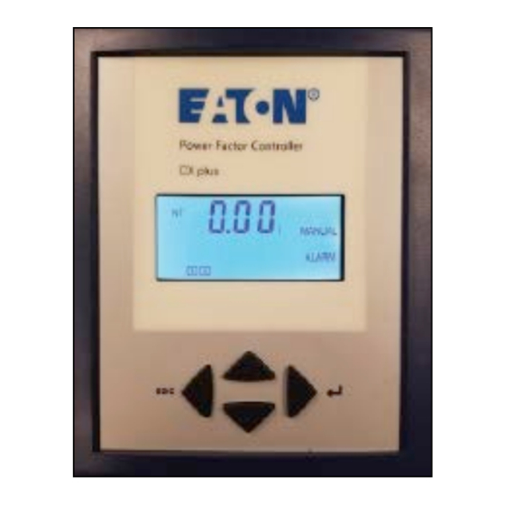
4. The CX Plus controller is shown below.
Figure 1. CX Plus controller
Figure 2. Digital display
Screen legend
INFO
Capacitor Database
AUTO
Automatic Mode
MANUAL
SETUP
Setup Mode
ALARM
Blinking during alarm
NT
Second target-pf is active
EXPORT
Export of active energy
1-12
Capacitor stage number indication
5. The CX Plus controller is operated
by using four keys.
Figure 3. Operational keys
Advertisement
Table of Contents

Related Manuals for Eaton CX Plus


Summary of Contents for Eaton CX Plus
- Page 1 2. Secure the controller in place using the tab slide-in mechanism (similar to the BLR-CX). 3. For catalog option “W” , caulk around the CX Plus controller (between the facia and the door cutout). 4. Reconnect all the following wires for UM1, UM2, A through 12, k and 1.
- Page 2 Instruction Leaflet IL159026EN Replacement instructions for CX with CX Plus controller Effective February 2022 6. Press the up or down keys to scroll through submenus. 16. Once the Menu 100 is programmed, press the left key three times to return to the main screen that displays the existing PF .
- Page 3 Instruction Leaflet IL159026EN Replacement instructions for CX with CX Plus controller Effective February 2022 Table 1. Default settings Customer Customer Menu Function Default settings Menu Function Default settings Quick start setup Setup capacitor database, continued Nominal voltage (phase-phase) 208 V / 240 V / Type of exit: step 1…max.
- Page 4 Instruction Leaflet IL159026EN Replacement instructions for CX with CX Plus controller Effective February 2022 Measurement Mode U Voltage ULL (V) ▼ U Voltage ULN (V) ▼ I Current (A) ▼ P active power (W) ▼ Main screen Q reactive power (VAR) ▼...
Need help?
Do you have a question about the CX Plus and is the answer not in the manual?
Questions and answers