
Related Manuals for CellarCool CM TWIN H.E.

Summary of Contents for CellarCool CM TWIN H.E.
- Page 1 OWNER’S MANUAL NOTICE: To activate the split system warranty, the installing certi ed HVAC/R service tech must complete the split system warranty checklist and send back to CellarCool.
- Page 2 CellarCool. Every effort has been made to ensure that the information in this manual is accurate. CellarCool is not responsible for printing or clerical errors.
-
Page 4: Customer Service
INTRODUCTION Customer Service Thank you for purchasing a CellarCool cooling system. We strive to provide the highest-quality products and the best possible customer service. If you have any questions about your system, please call us at 1-800-343-9463 or visit cellarcool.com. -
Page 5: Before You Start
CellarCool requires that all split systems be installed by a certified HVAC-R technician only. NATE or equivalent is recommended If you encounter a problem with your CellarCool system, please refer to the Troubleshooting Guide. If you have any further questions or concerns, or need technical assistance, please contact CellarCool’s Customer Service at 1-800-343-9463. Please be sure all testing has been completed prior to contacting Customer Service. - Page 6 e side e Wall & Ceiling Framing Insulation Vapor Barrier Page 4 08/09/21...
- Page 7 Unobstructed Airflow Door and Door Seal ade (1¾ Ventilation The necessity of dissipating heat away from the condensing unit is critical to the unit’s performance and cannot be overstated. As the system operates and cools, a greater amount of heat is generated on the condensing side of the system. Adequate ventilation is required in order to dissipate heat away from the condensing unit.
- Page 8 • Use caution when lifting and check package for damage. • Lift only at the designated hand-hold locations on the shipping container, or fully support the container from underneath. A shipment may include one or more boxes containing accessories. • Before opening the container, inspect the packaging for any obvious signs of damage or mishandling.
- Page 9 QUICK REFERENCE GUIDE or Unit (Fan Coil Unit) Line Set Knockout (x6) Elec ical K Supply and R n Gr ting Br op P Line Set K Options Elec ical K Options Page 7 08/09/21...
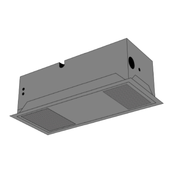
- Page 10 OUT L TIONS Top View of Evaporator Unit PROPRIETARY AND CONFIDENTIAL View of Evaporator Unit Front View of Evaporator Unit Page 8 08/09/21...
- Page 11 Setting up the Bottle Probe: Page 9 08/09/21...
- Page 12 Route the refrigerant lines from each evaporator unit toward each other using OD copper tubing for the suction line and 1⁄4” OD tubing for the liquid lines. Join both suction lines together using a T-fitting. Install a ” to reducer at the outlet of the T-fitting. The remainder of the suction line from the T-fitting to the condensing unit will need to be ”...
- Page 13 Route a standard 18-5 thermostat wire into the evaporator unit. Locate the 18-5 thermostat wires inside of the evaporator unit. Connect the wires according to color: yellow to yellow, red to red, green to green, and blue to blue. Connect the red adapter wire to the end of the white thermostat wire.
- Page 14 Minimum Tools Needed: T-square Hammer #2 Phillips-head screwdriver Locate the desired installation location. Using a stud nder, locate the ceiling joists on either side of the center point. Cut and frame 14.5” x 36” openings in the ceiling for each evaporator unit. Make sure the framing is su cient to support the weight of the cooling unit.
- Page 15 It is vital that the units be set apart and oriented so that the return air from one unit does not recirculate into the supply air of the other unit. If installing the units without attic access, perform steps 5-2 prior to steps 3-4. Secure the mounting bracket to the evaporator unit using the twelve (12) supplied ⁄...
-
Page 16: Top Panel
Unscrew the twenty-two (22) screws and remove the ELECTRICAL ACCESS PANEL TOP PANEL Remove the knockout(s) that you will be using to route The units come in black. The mounting brackets and front grilles are paintable, enabling you to match your desired color. - Page 17 Page 15 08/09/21...
- Page 18 *Tools required: spray adhesive, utility knife, cork tape, foil tape blanket dimensions 68” 22” Insulation Blanket Insulation Blanket 11.25” 11” blanket dimensions 102” 35.75” Insulation Blanket Insulation Blanket 14.25” 14.25” 1. Once mounting bracket location has been selected and installed, proceed to the insulation blanket installation. 2.
- Page 19 7. Spray the top of each evaporator unit with spray adhesive. (See spray adhesive directions for proper tack time before proceeding to step 8.) 8. Set piece (B) in place by pressing firmly on all surfaces of the insulation that come in contact with the top of each evaporator unit (see illustration).
- Page 20 1/4" Clear Plastic Tubing Proper Discharge Location Page 18 08/09/21...
- Page 21 90° Oblique Rough Warped ° ° Page 19 08/09/21...
- Page 22 Ø Ø Ø Ø Ø ° Ø Ø Ø Ø Ø ° Page 20 08/09/21...
- Page 23 , ush moun , ush moun Page 21 08/09/21...
- Page 24 Page 22 08/09/21...
- Page 25 Page 23 08/09/21...
- Page 26 e the ush moun INST THE E APOR Page 24 08/09/21...
- Page 27 Page 25 08/09/21...
- Page 28 Page 26 08/09/21...
- Page 29 Page 27 08/09/21...
- Page 30 Page 28 08/09/21...
- Page 31 Page 29 08/09/21...
- Page 32 Page 30 08/09/21...
- Page 33 • • • • Page 31 08/09/21...
- Page 34 Page 32 08/09/21...
- Page 35 Page 33 08/09/21...
- Page 36 Ø Ø Ø Ø Ø Page 34 08/09/21...
- Page 37 ” Suction Line ” Liquid Line ” Page 35 08/09/21...
- Page 38 Page 36 08/09/21...
- Page 39 Page 37 08/09/21...
- Page 40 Page 38 08/09/21...
- Page 41 Washable lter is installed from the factory on the return side of the grille, secured via Velcro strips. Page 39 08/09/21...
- Page 42 • Line set, drain tube and electrical connections have been relocated to be accessible from the bottom (cellar side / grille side) located on return side of unit. • Can be accessed by removing the grille. • Flare fittings have been added to the line set. •...
- Page 43 • Ceiling mount now comes equipped with a 2-speed fan switch. • Located on the electrical panel. Access by removing grille and internal access panel. • Speed is sent from factory set to High. Flip the switch to adjust down to Medium speed. Page 41 08/09/21...
- Page 44 Model Page 42 08/09/21...
- Page 45 Model * Sizing the System to the Room There are several factors such as glass, stone, and concrete which will change the required amount of BTUs needed to properly cool your wine room. We strongly recommend utilizing the cellar wizard on the website in order to ensure you are selecting the proper cooling system for your application.
- Page 46 on r Page 44 08/09/21...
- Page 47 ait v his v or the rst Page 45 08/09/21...
- Page 48 ti ed y will not a w ake ic Page 46 08/09/21...
- Page 49 w su cien fan o s o af “fan o “fan o ts of v w su cien Page 47 08/09/21...
- Page 50 Possible cause Solution or lt e the lt or v ush with fr Possible cause Solution Possible cause Solution e air o Possible cause Solution Page 48 08/09/21...
- Page 51 Possible cause Solution er can o Possible cause Solution Lack of air o or lt em o f ooler air o Possible cause Solution w ake symbol illumina or lt em o f ooler air o Possible cause Solution Possible cause Solution Possible cause Solution...
- Page 52 Page 50 08/09/21...
- Page 53 Page 51 08/09/21...
- Page 54 Page 52 08/09/21...
-
Page 55: Technical Assistance
TECHNICAL ASSISTANCE CellarCool Customer Service is available Monday through Friday from 6:00 a.m. to 4:00 p.m. Paci c Standard Time. The appointed customer service representative will be able to assist you with your questions and warranty information more e ectively if you provide them with the following: •... - Page 56 CellarCool warrants against defects in material and workmanship as follows: 1. LABOR - For a period of two (2) years commencing on the date of purchase, CellarCool will, at its option and discretion, reimburse up to $250 to the End User for cost incurred for servicing, repairing, removing or installing warranty parts.
- Page 57 8. This limited warranty is voided if installed in an enclosure of insu cient design that does not follow the Product installation requirements stated herein and in the owner’s manual. 9. Removing the rivets from the Product’s unit housing without prior authorization from CellarCool voids this limited warranty.
- Page 58 E. End User is responsible for all costs incurred for the installation and/or removal of the Product, or any part thereof, unless such cost has been agreed by CellarCool to be a warranty repair prior to the work being performed.
- Page 59 Conditions of Sale shall be interpreted as through drafted jointly by CellarCool and Purchaser. Any dispute will be resolved by the courts in and for the County of San Joaquin, State of California, and all parties, CellarCool, Purchaser and End User, hereby irrevocably submit to the personal jurisdiction of such courts for that purpose.
- Page 60 Web: www.cellarcool.com B. Technical Assistance. CellarCool Customer Service is available Monday through Friday from 6:30 a.m. to 4:00 p.m. PST. The Customer Service representative will be able to assist you with your questions and warranty information more e ectively if you provide them with the following: 1.
- Page 61 CellarCool 1738 E. Alpine Ave Stockton, CA 95205 1(800) 343-9463 www.cellarcool.com...
Need help?
Do you have a question about the CM TWIN H.E. and is the answer not in the manual?
Questions and answers