Table of Contents
Advertisement
Quick Links
Advertisement
Table of Contents

Related Manuals for Mimomax TORNADO X

Summary of Contents for Mimomax TORNADO X
- Page 1 Product Manual for Tornado X and Tornado XR PRODUCT MANUAL FOR TORNADO X & TORNADO XR Issue 1 – June 2021 FCC ID:XMK-MMXTRNXB001 This document contains proprietary information and must not be provided or copied to third parties without express permission from Mimomax Wireless Ltd...
- Page 2 Disclaimer While precaution has been taken in the preparation of this literature and it is believed to be correct at the time of issue, Mimomax Wireless Ltd assumes no liability for errors or omissions or for any damages resulting from the use of this information. Due to a policy of continuous technical improvement, the contents of this document and any specifications contained therein are subject to revision and may change without notice.
- Page 3 Mimomax product, software or services or by reason of any act or omission on the part of Mimomax.
-
Page 4: Table Of Contents
Optimized Protection Variant (OPV) ...................... 11 Safety Warnings ............................13 Modifications ............................13 Transmitter Antenna ..........................13 2.2.1 Tornado X and Tornado XR 700MHz Transmitter Antenna ..............13 Safety Distance ............................. 13 2.3.1 Tornado X and Tornado XR 700MHz Safety Distance ..............13 FCC RF Exposure Statement ........................ - Page 5 Product Manual for Tornado X and Tornado XR Setting Up on the Bench ..........................21 Testing the Network Setup ........................22 Configuration Control and Monitoring System (CCMS) ................. 24 Changing Operating Frequency and Power Calibration ................25 Introduction ............................25 Equipment Required: Power Meter .......................
- Page 6 Product Manual for Tornado X and Tornado XR Abbreviations And Acronyms Alternating Current ACMA Australian Communications and Media Authority Analogue to Digital Converter ADPCM Adaptive Differential Pulse Code Modulation Automatic Frequency Control Automatic Gain Control Antenna Bit Error Rate Base Radio Unit...
- Page 7 Product Manual for Tornado X and Tornado XR HTML Hyper-Text Mark-Up Language Intermediate Frequency Input Output Internet Protocol International Telecommunication Union Light Emitting Diode Low Noise Amplifier Local Oscillator Low Pass Filter Link Radio Unit Media Access Control MCAM Mimomax Cognisant Adaptive Modulation...
- Page 8 Product Manual for Tornado X and Tornado XR Real-Time Protocol Radio Unit Receive SCADA Supervisory Control and Data Acquisition SEPIC Single Ended Primary Inductor Converter Software Feature Enabler Sub miniature Version B SNMP Simple Network Management Protocol Serial Peripheral Interface...
-
Page 9: Tornado X System Overview
Mimomax’s renowned reputation for reliability and operational efficiency. There are two different form factors for Tornado X series: Tornado X and Tornado XR. Tornado X radio can be configured as Network Digital Links (NDL) and Multipoint Digital Links (MDL) and Optimized Protection Variant (OPV) of the NDL link. -
Page 10: Multipoint Digital Links (Mdl)
Very high system gains and good receiver sensitivities mean that it is possible to achieve paths in excess of 100kms from high radio sites at full speed. Furthermore, any branch of MDL can be extended by using the Mimomax point- to-point Network Digital Link (NDL) radio communications solution. -
Page 11: Optimized Protection Variant (Opv)
ROTECTION ARIANT The Mimomax OPV is a highly intelligent point-to-point radio system that provides complete rural substation Teleprotection communications solution for both power line protection and SCADA applications. It is designed to meet CAT I, II and III protection levels. Hence, can be employed to link power line protection relays (e.g. General Electric L90) within critical network infrastructure. - Page 12 Product Manual for Tornado X and Tornado XR Mimomax Tornado OPV-T Synchronous Serial Latency Table...
-
Page 13: Safety Warnings
28.06dBi or 12.83 dBi is allowed to use for 757-758MHz band and 787-788MHz band respectively. The use of other antennas with higher gain should be combined with tuning down the Tornado X or Tornado XR transmitter output power to appropriate level to assure the system E.R.P (or E.I.R.P) meets the FCC requirement. -
Page 14: Fcc Rf Exposure Statement
Product Manual for Tornado X and Tornado XR The above distances are based on procedures defined by regulatory standards for equipment operating at maximum power and 100% duty cycle with a person located directly in front of the antenna in the main radiation lobe. -
Page 15: Mains Connection
Product Manual for Tornado X and Tornado XR AINS ONNECTION The Mains connection of the supply providing the DC supply to the Mimomax Tornado X or XR unit shall be either: PERMANENTLY CONNECTED EQUIPMENT. • • PLUGGABLE EQUIPMENT TYPE B. -
Page 16: Tornado Radio Unit Overview
(either port can be used). The operating input voltage range of the power supply is 10.5 to 64 VDC. For Tornado X, the power supply must be able to supply at least 70 watts. For Tornado XR, the power supply must be able to supply at least 30 watts. -
Page 17: Digital Processing System
TCP/IP stacks and inter-networking, applications, user interface, system configuration and control etc. An integral part of the Linux operating system is the Mimomax specific network driver, which configures the radio unit as a standard Ethernet device. 3.2.3... -
Page 18: Receive Converters
(NDL and MDL) or providing a transparent end to end RS232 connection (NDL only). In a NDL system the serial ports are also able to provide X-21, RS422, G703, C37.94 or Mimomax HSSI2 via external interface converters. -
Page 19: Receiver Rf/If Sections
Product Manual for Tornado X and Tornado XR RF/IF S ECEIVER ECTIONS The receiver has two identical channels, each with separate RF, mixer and IF stages. A common local oscillator feeds both channels simultaneously. RF input to each channel is by means of a PCB-mounted 50Ω SMB connector. -
Page 20: Feedback Signal Path
The required main local oscillator frequency range is 757MHz to 788MHz (31MHz total for 700MHz Tornado X and XR). The secondary LO FPD is disciplined by the main LO and a 13.333333MHz reference clock. The secondary LO frequency range is 743.666666MHz to 774.666666MHz. -
Page 21: Setting Up On The Bench
30dB > 30W Note: If an NDL system or an MDL system with only one RRU is desired then the splitters, second RRU and corresponding attenuators can be omitted. Mimomax can supply a splitter that provides 4 ports and ~30dB attenuation. -
Page 22: Testing The Network Setup
Product Manual for Tornado X and Tornado XR ESTING THE ETWORK ETUP Once the RF setup has been completed the radio units can be powered up, networking on associated devices configured and the units logged into. Refer to the label located on the underside of the radio unit to identify the configured IP address and subnet mask. - Page 23 Product Manual for Tornado X and Tornado XR Figure 1 Ipconfig on the left (In this case the gateway has not been set properly!) and on the right Pinging 192.168.0.1 (the BRU) from Laptop A You are now ready to log in, configure, and monitor the system.
-
Page 24: Configuration Control And Monitoring System (Ccms)
Internet Explorer, Firefox or Chrome. No application other than a web browser needs to be installed on your PC or laptop. The radio unit serves up the CCMS web pages. For a full list of functions please refer to Mimomax’s... -
Page 25: Changing Operating Frequency And Power Calibration
6 CHANGING OPERATING FREQUENCY AND POWER CALIBRATION NTRODUCTION Changing operating frequencies of a Mimomax Tornado radio is done via the CCMS. The radio’s power will need to be recalibrated and the internal duplexers also need to be re-tuned. Duplexer tuning is covered in Section 7. - Page 26 Product Manual for Tornado X and Tornado XR Configure RF CCMS Page To change the Tx and Rx frequencies on the radio, click Retune Frequencies. This will take you to a new page. Retune Frequencies CCMS Page On this page, enter the new Tx and Rx frequencies. The above image shows an example of this. Afterwards, click...
-
Page 27: Power Calibration
Product Manual for Tornado X and Tornado XR Enter New Frequencies Page A warning appears that requests that the duplexers be re-tuned. OWER ALIBRATION The process for calibrating the transmitter power is described below. The process for calibrating the power using CCMS is different from the process when using CLI in terms of what users can do. -
Page 28: Calibrating Tx (Coarse Step)
Product Manual for Tornado X and Tornado XR Proceed with Cal Tx1 to calibrate the 1 transmitter or with Cal Tx2 to calibrate the 2 transmitter. These can be done in any order, but the following example will start with Tx1. The power at the current state is down and the carrier is turned On once one of these buttons is pressed. -
Page 29: Complete Calibration Of One Tx
Product Manual for Tornado X and Tornado XR 6.5.3 COMPLETE CALIBRATION OF ONE TX Pressing Calibrate the 2nd time, finishes the adjustments and if successful, the following screen will be shown: Users can abort the process at any time while still calibrating one of the Tx's by pressing the Abort button on this screen or on other process screens. -
Page 30: To Finish Power Calibration, Click Done Calibration Fault
Product Manual for Tornado X and Tornado XR DONE 6.5.5 TO FINISH POWER CALIBRATION, CLICK CALIBRATION FAULT Sometimes, the calibration process can fail. This will occur if the PG is out of range at the fine step. The system checks the resulting PG against limits and the PG must be inside them for the calibration to pass. On failure of one of the transmitters the following page will be show: This will result in failure and user will need to abort by pressing the Abort button. -
Page 31: Rssi Calibration
Product Manual for Tornado X and Tornado XR 7 RSSI CALIBRATION RSSI C ALIBRATION The Receiver RSSI may need be re-calibrated once the frequency of Transmitter and Receiver is swapped and the duplexer T/R end has been swapped. A signal generator (analog) like Agilent E4432B or similar ones can be used for the RSSI calibration. And a 30dB attenuator (best to have 30W power handling) should be used in between the signal generator and the Radio RF port. -
Page 32: Reference Calibration
Feed the 10 MHz source into the reference inputs of the GPIO/Ref/Alarm connector (Brown and Red wires on the Mimomax GPIO/Ref/Alarm cable). Note: the reference signal is differential, but it does not normally cause any problems if a non-differential signal is used, treat one of the differential connections as ground in this case. - Page 33 Product Manual for Tornado X and Tornado XR Reference calibration...
-
Page 34: Radio Reference Information
Product Manual for Tornado X and Tornado XR 8 RADIO REFERENCE INFORMATION ECHANICAL IMENSIONS AND OUNTING This section describes the dimensions of the Tornado radio unit and the various methods of mounting. 8.1.1 DIMENSIONS Mechanical Dimensions for Tornado XR (All units are in mm) -
Page 35: Mounting
Product Manual for Tornado X and Tornado XR Mechanical Dimensions for Tornado X (All units are in mm) 8.1.2 MOUNTING The radio unit can be mounted in Rack, Pole, Wall or DIN mount configurations. Each of these styles of mounting can be further customised further by collocating or separating aspects such as batteries and power supplies. - Page 36 Product Manual for Tornado X and Tornado XR 8.1.2.1 Rack Mount The Rack mount kit is designed to be used to mount the Tornado X and Tornado XR into a standard 19” rack enclosure, occupying 1U of rack height. Tools required are a #2 Philips screwdriver.
- Page 37 Product Manual for Tornado X and Tornado XR 8.1.2.2 Pole Mount The pole mount kit can be used to mount the tornado onto a pole with a diameter between 23 and 51 mm. If the tornado is mounted outside, then the weatherproof hood must be used. Tools required are a #2 Philips screwdriver and a 10 mm spanner.
- Page 38 Product Manual for Tornado X and Tornado XR 8.1.2.4 DIN mount The Tornado can also be mounted to a Top hat style DIN rail (EN 50022). Tools required are a #2 Philips screwdriver. Tornado XR DIN mount dimension (in Assembled and exploded view of the Tornado XR DIN mount...
- Page 39 Product Manual for Tornado X and Tornado XR Exploded view of the weatherproof hood Mounting orientation of the weatherproof hood 8.1.2.6 Mounting holes If other mounting options are desired, the mounting holes described as shown below can be used directly. Ensure...
-
Page 40: Input And Output
Product Manual for Tornado X and Tornado XR Mounting hole size, depth and location NPUT AND UTPUT This section describes the general I/O of the device. It includes an overview of all connectors as well as LED’s and other relevant electrical parameters. Refer to the Tornado serial manual for detailed information on the use of the... -
Page 41: Connectors
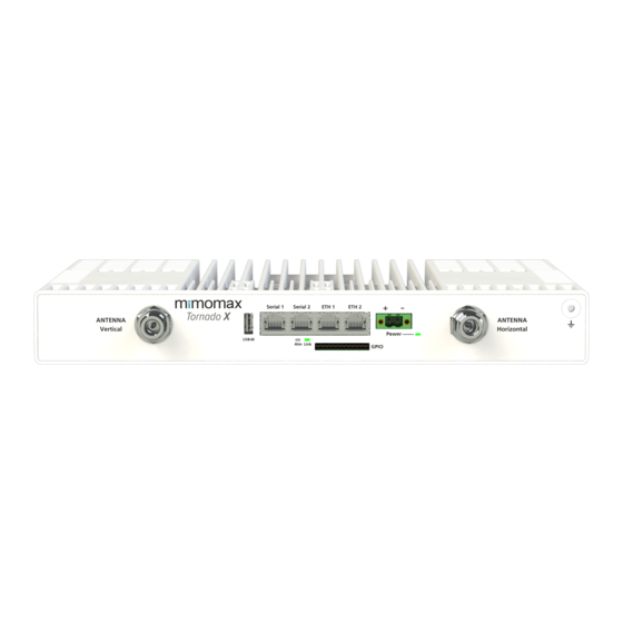
Product Manual for Tornado X and Tornado XR Radio Connections and LEDs 8.2.1 CONNECTORS Antenna/Duplexer ports (2x N connectors) The radio unit is a 2x2 MIMO unit with internal duplexers. This means each N connector is both a transmit and a receive port. -
Page 42: Essential Power Requirements
Product Manual for Tornado X and Tornado XR NDL: The Link LED lights up when an RF link is active. RRU: The Link LED has four different modes of operation each indicating a different RF link state. It is off when the RRU is not detecting a signal from the BRU. - Page 43 8.2.3.7 Operating from AC Mains: AC-DC ‘desktop’ power supplies are available from Mimomax with the required power. 8.2.3.8 Choice of power supply cable size The table below indicates the maximum length of cable that can be used for given supply voltages and cable sizes.
- Page 44 Product Manual for Tornado X and Tornado XR Approx. Cross sectional area (mm (Vmin = 11V) (Vmin = 18V) (Vmin = 36V) 1.85 3.5m 175m 4.5m 7.2m Max loop resistance 0.06 Ω 1.0 Ω 3.2 Ω Table 3: Recommended maximum cable length for a given supply cable size Note 1: The Phoenix Contact MSTB 2,5 HC plug can support stranded wire with a cross sectional area between 0.2 mm...
-
Page 45: Electrical Characteristics
Product Manual for Tornado X and Tornado XR ELECTRICAL CHARACTERISTICS Parameter Conditions Typical Max Units Power supply Input voltage Normal operation 10.5 Power Consumption Idle, Tx off Power Tx Active 100% 67.5 73.5 Consumption(Tornado X) Power Tx Active 25% 22.5 28.5... - Page 46 Product Manual for Tornado X and Tornado XR Current Sinking Capability Output driving low Input Impedance kOhms Alarm Input current (max) Switching voltage (max) Parameter Conditions Typical Max Units Reference input Level Frequency Reference output Level Frequency USB Host VBus Output Current...
-
Page 47: Interface Ports
MDI-X, auto negotiation, half & full duplex operation and flow control. These parameters can be configured in the network section of CCMS. 8.2.4.2 Asynchronous Serial (RS232) The Tornado RS232 pin out is as per the EIA/TIA – 561 standards. Note: this is different to older Mimomax products. Signal Name Pin number... - Page 48 Product Manual for Tornado X and Tornado XR Next use the GPIO input calibration process to calibrate the system through the external resistor. This • process will be based on a known voltage before the resistor. GPIO Input Circuit GPIO as digital output: The GPIO pins provide an open collector output, which can be used to drive a relay or generate a level.
-
Page 49: Rf Specification
Product Manual for Tornado X and Tornado XR Closed in Alarm Black Not Connected Table 5: GPIO pin out GPIO Connector 8.2.5 RF SPECIFICATION General Configuration 2x2 MIMO Connector type N-Type, 50 Ohms Ambient Temperature Range C to +60 C Horizontal mount, all products... - Page 50 Product Manual for Tornado X and Tornado XR 12.5 kHz 33/66/98/131 kbps Full-duplex Receiver Modulation QPSK/16/64/256QAM Number of MIMO Receivers Symbol Rate 50 kHz 2x40k symbols/sec 25 kHz 2x20k symbols/sec 12.5 2x10k symbols/sec Modulation sensitivity for 10 50 kHz -111/-104/-98/-91 dBm...
- Page 51 Product Manual for Tornado X and Tornado XR RF Power Control Range >20 dB RF Power Control Resolution 0.5 dB Frequency Range 757 to 758 and 787 to 788 MHz Frequency Accuracy Better than +/-1 ppm Stability Transmitter (continued) Adjacent Channel Power Ratio >60 dB...
- Page 52 Product Manual for Tornado X and Tornado XR Equipment location It is recommended that the radio unit is installed in a dry, dust-free room. If this is not possible then the waterproof boot must be fitted to protect the unit.
-
Page 53: Installation
Product Manual for Tornado X and Tornado XR 45º cone of protection Earthing kit Coax to Polyphase cabinet discharge unit 1/2" heliax cable Earthing kits Lightning protection A gas discharge unit is required to release high voltage charges developed between the cable inner and outer. - Page 54 Product Manual for Tornado X and Tornado XR Typical pole and rack mounting options for the radio unit Note: refer to section 8.2.6.1 for grounding and lightning protection considerations. Regardless of the mounting configuration used, the appropriate site engineering must be undertaken. Site engineering must consider safety aspects such as grounding and lightening protection but also needs to take performance parameters such as antenna location, antenna separation and other RF sources.
-
Page 55: Compliances
Product Manual for Tornado X and Tornado XR OMPLIANCES RF Bands 757-758 & 787-788 MHz Radio Performance FCC 47CFR part 27 FCC 47CFR part 15 Environmental 60950-22 Outdoor Safety Safety IEC 60950-1:2005, Am 1:2009, EN 62368-1:2014 Table 7: Compliances... -
Page 56: Document History
Product Manual for Tornado X and Tornado XR 9 DOCUMENT HISTORY Issue # Date Description 13/April/2021 Update for Power Supply domain 25/May/2021 Information for RF part updated 10/June/2021 DC power updated...
Need help?
Do you have a question about the TORNADO X and is the answer not in the manual?
Questions and answers