Table of Contents
Advertisement
Advertisement
Table of Contents

Related Manuals for Mimomax TORNADO

Summary of Contents for Mimomax TORNADO
- Page 1 TORNADO RADIO UNIT PRODUCT MANUAL This document contains proprietary information and must not be provided or copied to third parties without express permission from MiMOMax Wireless Ltd FCC ID:XMK-MMXTRNB005 © MiMOMax Wireless Ltd Tornado Product Manual...
- Page 2 Whilst every precaution has been taken in the preparation of this literature and it is believed to be correct at time of issue, MiMOMax Wireless Ltd assumes no liability for errors or omissions or for any damages resulting from the use of this information. Due to a policy of continuous technical improvement the contents of this document and any specifications contained therein are subject to revision and may change without notice.
-
Page 3: Table Of Contents
TATEMENT ..........................11 LECTRICAL SAFETY CABLE SCREENING ..............................11 AINS CONNECTION FCC 15.19 S ...............................12 TATEMENT FCC 15.105( ............................12 TATEMENT TORNADO RADIO UNIT OVERVIEW ........................13 ................................13 ONNECTORS ............................14 IGITAL ROCESSING YSTEM 3.2.1 Power supply ..............................14 3.2.2 Central Processor Unit ............................14 3.2.3 FPGA ................................14... - Page 4 8.1.2 Mounting ................................33 ..............................37 NPUT AND UTPUT 8.2.1 Connectors ..............................38 8.2.2 LED Behaviour..............................38 8.2.3 Essential Power Requirements ........................39 8.2.4 Electrical Characteristics..........................42 8.2.5 Interface ports ..............................44 8.2.6 RF Specification ..............................46 ................................50 NSTALLATION ................................51 OMPLIANCES © MiMOMax Wireless Ltd Tornado Product Manual...
-
Page 5: Abbreviations And Acronyms
International Telecommunication Union Light Emitting Diode Low Noise Amplifier Local Oscillator Low Pass Filter Link Radio Unit Media Access Control MCAM MiMOMax Cognisant Adaptive Modulation MDAP MiMOMax Data Acceleration Protocols MDIX Medium Dependent Interface Crossover Multipoint Digital Link Management Information Base MIMO... - Page 6 Universal Asynchronous Receiver/Transmitter User Datagram Protocol Ultra-High Frequency United States Dollar Voltage Controlled Oscillator VCTCXO Voltage-Controlled Temperature-Compensated Crystal Oscillator VRMS Volts Root Mean Square VRRP Virtual Router Redundancy Protocol VSWR Voltage Standing Wave Ratio © MiMOMax Wireless Ltd Tornado Product Manual...
-
Page 7: Tornado System Overview
The MiMOMax Tornado radio platform is configurable in three types of system linking, Network Digital Links (NDL), Multi- Point Digital Links (MDL) and an Optimised Protection Variant (OPV) of the NDL link. The one Tornado radio platform can be configured differently for the different roles required by these links through the enabling and disabling of features and functionalities. -
Page 8: Multipoint Digital Links (Mdl)
Very high system gains and good receiver sensitivities mean that it is possible to achieve paths in excess of 100kms from high radio sites at full speed. Furthermore, any branch of MDL can be extended by using the MiMOMax point-to-point Network Digital Link (NDL) radio communications solution. -
Page 9: Optimised Protection Variant (Opv)
ROTECTION ARIANT The MiMOMax OPV is a highly intelligent point-to-point radio system that provides complete rural substation Tele protection communications solution for both power line protection and SCADA applications. It is designed to meet CAT I, II and III protection levels. Hence, can be employed to link power line protection relays (e.g. General Electric L90) within critical network infrastructure. - Page 10 OPV Example Network Diagram © MiMOMax Wireless Ltd Tornado Product Manual...
-
Page 11: Safety Warnings
Minimum Safe Distance from Antenna: To comply with safety requirements for human RF exposure in the USA, Canada and other countries, no person shall be permitted to remain in the vicinity of the antenna of an operational MiMOMax Tornado system at distances closer than the following: General Public/Uncontrolled Use: 0.16m when using an 8dbi Panel Antenna with a MiMOMax 700MHz radio. -
Page 12: Fcc 15.19 Statement
—Increase the separation between the equipment and receiver. —Connect the equipment into an outlet on a circuit different from that to which the receiver is connected. —Consult the dealer or an experienced radio/TV technician for help. © MiMOMax Wireless Ltd Tornado Product Manual... -
Page 13: Tornado Radio Unit Overview
Tx/Rx frequency pair. An NDL system consists of one ‘master’ NDL unit tuned to one frequency pair with its corresponding ‘slave’ unit tuned to the opposite pair. MiMOMax Tornado radios consist of the following modules. • Digital Processing System (DPS) •... -
Page 14: Digital Processing System
TCP/IP stacks and inter-networking, applications, user interface, system configuration and control etc. An integral part of the Linux operating system is the MiMOMax specific network driver, which configures the radio unit as a standard Ethernet device. -
Page 15: Dual Serial
The two serial ports, ‘Serial 1’ and ‘Serial 2’ on the front panel, operate as RS232 ports can either operate via a terminal server application (NDL and MDL) or providing a transparent end to end RS232 connection (NDL only). In a NDL system the serial ports are also able to provide X-21, RS422, G703, C37.94 or MiMOMax HSSI2 via external interface converters. 3.2.9... -
Page 16: Transmitter Rf/If Sections
Electrically the two duplexers in each radio unit are identical. Physically they are different and present almost a mirror image of the other. These are referred to as ‘Channel 1’ and ‘Channel 2’. The duplexers cannot be swapped over. © MiMOMax Wireless Ltd Tornado Product Manual... -
Page 17: Setting Up On The Bench
Note: If an NDL system or an MDL system with only one RRU is desired then the splitters, second RRU and corresponding attenuators can be omitted. MiMOMax can supply a splitter that provides 4 ports and ~30dB attenuation. ©... -
Page 18: Testing The Network Setup
First, we connect to each radio unit locally. To do this, configure the IP address, subnet mask and gateway of the connected device or laptop. It is crucial that the laptops/devices are on the same subnet as the Tornado’s and also that their gateway is set to the Tornado’s IP address. - Page 19 Next confirm network connectivity by pinging each radio unit from the connected laptop. If this is not successful, use ipconfig to check your networking settings. Once we have network connectivity with the local radio unit, type the appropriate IP address into your web browser to access the unit. © MiMOMax Wireless Ltd Tornado Product Manual...
- Page 20 Figure 1 Ipconfig on the left (In this case the gateway has not been set properly!) and on the right Pinging 192.168.0.1 (the BRU) from Laptop A You are now ready to log in, configure, and monitor the system. © MiMOMax Wireless Ltd Tornado Product Manual...
-
Page 21: Configuration Control And Monitoring System (Ccms)
CONFIGURATION CONTROL AND MONITORING SYSTEM (CCMS) CCMS is web-based software that enables you to connect to a MiMOMax radio unit using a web browser such as Internet Explorer, Firefox or Chrome. No application other than a web browser needs to be installed on your PC or laptop. The radio unit serves up the CCMS web pages. -
Page 22: Changing Operating Frequency And Power Calibration
CHANGING OPERATING FREQUENCY AND POWER CALIBRATION NTRODUCTION Changing operating frequencies of a MiMOMax Tornado radio is done via the CCMS. The radio’s power will need to be recalibrated and the internal duplexers also need to be re-tuned. Duplexer tuning is covered in Section 7. - Page 23 Channel 1 Transmitter then select the Calibration link. Navigate through the drop down menu to TX Power Calibration. The Channel 1 transmitter will turn on immediately when entering the TX Power Calibration Screen so it is important to already have the power meter connected. Enter New Frequencies Page © MiMOMax Wireless Ltd Tornado Product Manual...
-
Page 24: Power Calibration
(the coarse step), During this step the duplexer loss in the RF EEPROM will be adjusted once Calibrate is pressed. This click will take the user to the 2nd calibration step, called the fine step. © MiMOMax Wireless Ltd Tornado Product Manual... -
Page 25: Calibrating Tx (Fine Step)
CCMS and CLI which allows abort at any time unless you've already issued a confirm. 6.5.4 Complete both transmitter calibration The next page shows up when both transmitters were successful in their calibration. © MiMOMax Wireless Ltd Tornado Product Manual... -
Page 26: Calibration Fault
PG against limits and the PG must be inside them for the calibration to pass. On failure of one of the transmitters the following page will be show: This will result in failure and user will need to abort by pressing the Abort button. © MiMOMax Wireless Ltd Tornado Product Manual... -
Page 27: Duplexer Tuning Guide
• In the case of the Tornado duplexer, the Low Noise Amplifier for the Receive path has been integrated onto the duplexer printed circuit board. This manual covers internal duplexer tuning for 400 – 470 MHz radios. 700 MHz radios do not require duplexer tuning and duplexers should not be tuned in the 900 MHz range. -
Page 28: Tools/Equipment Required
‘H’ next to the RF connector. MiMOMax Tornado Duplexers in Chassis There are 3 sub-bands of duplexer to cover the entire 400-470MHz switching range. The sub-bands are 400 - 430MHz, 420 - 450MHz and 440 - 470MHz. -
Page 29: Procedure
Port, Connect +5V (If you keep the duplexer in the chassis, with +5V connected, you can use the radio +5V by powering the radio unit during calibration). Ensure TX and Rx duplexer is completely detuned away from the frequency of operation. © MiMOMax Wireless Ltd Tornado Product Manual... -
Page 30: Rssi Calibration
Select Rx1 in the CCMS page. Select -50dBm in the CCMS page. Click Read in the CCMS page. Set signal generator level so that -90dBm can be measured at the receiver input. Select -90dBm in the CCMS page. © MiMOMax Wireless Ltd Tornado Product Manual... -
Page 31: Reference Calibration
Feed the 10 MHz source into the reference inputs of the GPIO/Ref/Alarm connector (Brown and Red wires on the MiMOMax GPIO/Ref/Alarm cable). Note: the reference signal is differential, but it does not normally cause any problems if a non-differential signal is used, treat one of the differential connections as ground in this case. - Page 32 In CCMS, navigate to ‘Calibration’ > ‘Reference Calibration’. Click ‘Start’. If the calibration is successful the message, ‘A 10 MHz reference has been found. The calibration process was successful’ will be displayed. Reference calibration © MiMOMax Wireless Ltd Tornado Product Manual...
-
Page 33: Radio Reference Information
RADIO REFERENCE INFORMATION ECHANICAL DIMENSIONS AND OUNTING This section describes the dimensions of the Tornado radio unit and the various methods of mounting. 8.1.1 Dimensions Mechanical Dimensions (All units are in mm) 8.1.2 Mounting The radio unit can be mounted in Rack, Pole, Wall or DIN mount configurations. Each of these styles of mounting can be further customised further by collocating or separating aspects such as batteries and power supplies. - Page 34 Pole Mount The pole mount kit can be used to mount the tornado onto a pole with a diameter between 23 and 51 mm. If the tornado is mounted outside, then the weather proof hood must be used. Tools required are a #2 Philips screwdriver and a 10 mm spanner.
- Page 35 Assembled and exploded view of the Tornado wall mount 8.1.2.4 DIN mount The Tornado can also be mounted to a Top hat style DIN rail (EN 50022). Tools required are a #2 Philips screwdriver. Assembled and exploded view of the Tornado DIN mount 8.1.2.5 Weatherproof hood The weatherproof hood can be used to protect the Tornado interfaces from dust or moisture ingress.
- Page 36 Mounting holes If other mounting options are desired, the mounting holes described as shown below can be used directly. Ensure that bolts of the correct diameter and depth are used, otherwise damage may occur. © MiMOMax Wireless Ltd Tornado Product Manual...
-
Page 37: Input And Output
This section describes the general I/O of the device. It includes an overview of all connectors as well as LED’s and other relevant electrical parameters. Refer to the Tornado serial manual for detailed information on the use of the serial interfaces. -
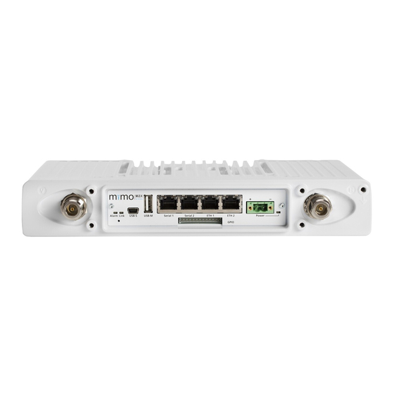
Page 38: Connectors
Each Ethernet port has a green and an orange LED. The green LED flashes when the port is receiving data. The orange LED is off when the port is 10 Mbit/s and on when it is 100 Mbit/s. © MiMOMax Wireless Ltd Tornado Product Manual... -
Page 39: Essential Power Requirements
This internal grounding is designed for EMC and transient protection currents. The RU casting is tapped to take a M4 x 8mm screw for grounding purpose. © MiMOMax Wireless Ltd Tornado Product Manual... - Page 40 The supply current should be kept under 1A when using power over Ethernet including accounting for voltage drop over the cable. A 48V AC-DC power supply suitable for use with the MiMOMax implementation of PoE is available.
- Page 41 PoE Splitter Sealed PoE Splitter © MiMOMax Wireless Ltd Tornado Product Manual...
-
Page 42: Electrical Characteristics
Input Low Threshold Temperature ambient = Input High Threshold Temperature ambient = 5VPC Output Current GPIO Input voltage Input -0.3 Current Sinking Output driving low Capability Input Impedance kOhms Alarm Input current (max) © MiMOMax Wireless Ltd Tornado Product Manual... - Page 43 VBus Output Current Input voltage Voltage on Dm and Dp -0.3 5.25 pins USB Device Input voltage Voltage on Dm and Dp 5.25 pins Vbus Voltage on VBus pin Table 3: Electrical characteristics © MiMOMax Wireless Ltd Tornado Product Manual...
-
Page 44: Interface Ports
MDI-X, auto negotiation, half & full duplex operation and flow control. These parameters can be configured in the network section of CCMS. 8.2.5.2 Asynchronous Serial (RS232) The Tornado RS232 pin out is as per the EIA/TIA – 561 standards. Note: this is different to older MiMOMax products. Signal Name Pin number Direction... - Page 45 The GPIO pins provide an open collector output, which can be used to drive a relay or generate a level. The current can be up to 100 mA. GPIO Output Circuit Signal Name Pin number Colour on MiMOMax cable Not Connected Ext Ref n Brown Ext Ref p...
-
Page 46: Rf Specification
320/480/640 kbps Full-duplex Rate (16/64/256 QAM) 25 kHz 160/240/320kbps Full-duplex 12.5kHz 80/120/160kbps Full-duplex Receiver Modulation QPSK/16/64/256QAM Number of MIMO Receivers Symbol Rate 50 kHz 240k symbols/sec 25 kHz 2x20k symbols/sec 12.5 2x10k symbols/sec © MiMOMax Wireless Ltd Tornado Product Manual... - Page 47 Resolution Frequency Range 400 to 470 MHz, 757 to 758 and 787 to 788 MHz, 806 to 960 MHz, 136 to 174 MHz Frequency Accuracy and Better than +/-1 ppm Stability Transmitter (continued) © MiMOMax Wireless Ltd Tornado Product Manual...
- Page 48 Lightning protection Lightning protection is important to ensure the protection of the tower, antenna and the radio equipment hardware. Below shows the point earthing concept recommended. © MiMOMax Wireless Ltd Tornado Product Manual...
- Page 49 The transmitting variant is the larger. It is very important that these variants are not confused because the lower discharge potential rating for the receiver unit will be triggered by transmitting voltages. This will cause a high VSWR and poor performance. © MiMOMax Wireless Ltd Tornado Product Manual...
-
Page 50: Installation
Regardless of the mounting configuration used, the appropriate site engineering must be undertaken. Site engineering must consider safety aspects such as grounding and lightening protection but also needs to take performance parameters such as antenna location, antenna separation and other RF sources. Please contact MiMOMax if more information in these areas is required. -
Page 51: Compliances
IEC 60950-1: 2005, Am 1:2009 RF Bands 806 to 960 MHz Radio Performance FCC 47CFR part 101 IC Canada (RSS-119) FCC47CFR part 15 Safety IEC 60950-1: 2005, Am 1: 2009 Table 6: Compliances © MiMOMax Wireless Ltd Tornado Product Manual...
Need help?
Do you have a question about the TORNADO and is the answer not in the manual?
Questions and answers