Midea V4 Plus R Series Instruction Manual
Hide thumbs
Also See for V4 Plus R Series:
- Service manual (165 pages) ,
- Technical & service manual (225 pages)
Advertisement
Quick Links
Control System
2.6 V4 Plus R Series: KJR-120B
Wired controller specifications
Performance features
1. Operating mode: cool, heat, dry, fan and auto.
2. Set the mode through buttons.
3. Indoor setting temperature range: 17°C ~30°C.
4. LCD (Liquid Crystal Display).
5. Auto mode for V4 plus R series.
2.6.1 Functions summary
The controller has functions as follows:
1) Can compatible with the V4 plus heat recycling 3-pipe system and V4 plus 2-pipe system.
2) Clock and Timer function;
3) Auto-restart function;
4) Query function;
5) Indoor unit error display function
6) Auto mode and air filter cleaning reminding function
7) Can
switch Fahrenheit degree and Centigrade
67
Model
Power Supply Voltage
Ambient Temperature Range
Ambient Humidity Range
KJR-120B
KJR-120B/BKP-E
DC 5.0 V
-5°C~+43°C
RH40%~RH90%
degree.
Control System
Advertisement

Related Manuals for Midea V4 Plus R Series


Summary of Contents for Midea V4 Plus R Series
- Page 1 2. Set the mode through buttons. 3. Indoor setting temperature range: 17°C ~30°C. 4. LCD (Liquid Crystal Display). 5. Auto mode for V4 plus R series. 2.6.1 Functions summary The controller has functions as follows: 1) Can compatible with the V4 plus heat recycling 3-pipe system and V4 plus 2-pipe system.
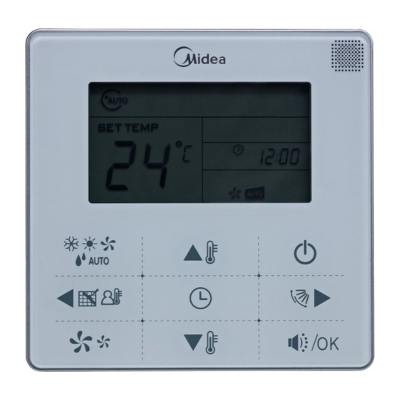
- Page 2 Control System 2.6.2 Appearance Operating Mode Locking Icon Transmitting Icon Function Icon Timer/Clock Setting Display Area Temperature Operating Fan Speed Operating Ico n Swing Icon ON/OFF MODE Button Button Left Button Right Button FAN SPEE D Silent/OK Button Button Temp. Setting Button Timer/Clock Setting Button (2) ON/OFF button Press the On/Off button to control the indoor unit on and off state.
- Page 3 Control System (3) Clock setting First power on or reset the wired controller, the clock will display 12:00. Long pressing the Timer/CLOCK button for 2 seconds can enter to the clock setting state. At this time, the minute position will be flashed; press button can adjust the minute.
- Page 4 Control System The setting temperature cannot be adjusted under the FAN mode. (7) Swing function Press the swing button to activate the swing function when the fan of indoor unit is turned on, and the swing icon will be lighted up. Press this button again can turn off the swing function, and the swing icon lights off.
-
Page 5: Codes Description
Control System 2) The wired controller will set the unit to operate on heating mode when Ts minus the Tf difference value is over than ΔT, and changeover to cooling mode when Ts minus the Tf difference value is less than -ΔT. The minimum operating mode switching interval is 15 minutes. -
Page 6: Installation
Control System ② The value of this first code "X" is "0", press the temperature setting button to adjust the second code value; ③ After setting the second code value, press Silent/Ok button to switch the first code to the next value;... - Page 7 Control System ※ Preparation before Installation: Make sure the following pasts has been prepared. Name QTY. Remarks Wired Controller Wood mounting screw M4×20(For mounting on the wall) mounting screw M4×25(For mounting on the electrical switch box) Installation manual Owner's manual Plastic screw bar For fixing on the 86 electrician box Switching wires for...
- Page 8 Control System Notes: 1) This wired controller is compatible with the indoor unit of V4 plus heat recycling 3-pipe system and V4+ 2-pipe system. 2) Please do not connect the wired controller and a CCM. to the same X, Y ,E port, otherwise it will lead to conflict.
- Page 9 Control System 5) Wiring figure A. Wiring, three outlet positions Top side Upper left wire outlet wire outlet Left middle side wire outlet Cutting place of top Cutting place of upper Cutting place of left side wire outlet left wire outlet middle side wire outlet Fig.5...
Need help?
Do you have a question about the V4 Plus R Series and is the answer not in the manual?
Questions and answers