
Subscribe to Our Youtube Channel
Related Manuals for Shin-Nippon SLM-5000


Summary of Contents for Shin-Nippon SLM-5000
- Page 1 Auto Lensmeter SLM-5000 Operations Manual <Important> Read this manual thoroughly before use. Keep this manual on hand at all times. RB-473-B02M...
- Page 2 INTRODUCTION This manual provides you information on correct handling and operational procedures as well as safety considerations pertinent to the SLM-5000. Before carrying out any measurements, read the instructions thoroughly so that effective operation is ensured. As this continues an important reference and user guide, be sure to keep it on hand at all times.
- Page 3 SAFETY CONSIDERATION General Precautions SLM-5000 is NOT a medical device. Fingerprints or dust on the optical parts such as lenses may affect the measurement accuracy. Always avoid touching such parts with fingers and keep away from dust getting on them.
- Page 4 The dirty terminal may cause malfucntion or fire. Always use SLM-5000 with the rated powe voltage. Using the instrument out of the rated voltage range may cause malfunction or fire. ...
-
Page 5: Table Of Contents
Contents Parts Identification........................5 1.1. Overview ..........................5 1.2. Accessories ...........................6 Installation Environment......................7 Safeguard Summary ......................... 8 Measurement Screen........................ 9 4.1. Switch Function........................9 4.2. Each Setting ........................10 4.2.1. Set up Screen ......................10 4.2.2. ID Screen ........................11 4.2.3. RS 232C Screen......................12 4.2.4. -
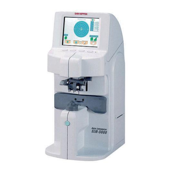
Page 6: Parts Identification
1. Parts Identification 1.1. Overview Color LCD monitor Operation switches Indicator Lens holder Marking lever Lens stand Lens plate Memory/Add switch Rating nameplate RS-232C terminal Power inlet Power switch Printer RB-473-B02M... -
Page 7: Accessories
1.2. Accessories When you unpack the box, please check the followings are all packed without any damages. Contact your distributor if any accessories are missing or damaged. Power cord Contact lens stand Rolls of printer paper Printer shaft ... -
Page 8: Installation Environment
2. Installation Environment Do not expose the optic parts, i.e. lens stand, directly to sunlight or bright light from other sources. Strong light or glare to the instrument may cause the failure of measurement. Do not install the instrument in places where either dust or rubbish may accumulate. -
Page 9: Safeguard Summary
At no time use organic solvents which will damage the water based paint finish of the instrument. SLM-5000 is a precision optical instrument. Handle with care at all times, making sure not to accidentally drop it. If the instrument is not to be used for any length of time, remove the power cord from the outlet. -
Page 10: Measurement Screen
4. Measurement Screen Operation mode display area Axis angle marks Measuring Spherical value 0.00 0.00 Cylindrical value Axis angle Measurement area I 0.00 Prism value: X direction U 0.00 Prism value: Y direction Abbe number Abbe Step Measurement increment ± Marking OK Alignment status/ Cylindrical sign... -
Page 11: Each Setting
4.2. Each Setting 4.2.1. Set up Screen You can set each measurement condition in the Set up screen. Set up Set up Step 0.25 0.12 0.01 Prism(mm) S/R/L Lens Switch Abbe H Cont S Cont Lens Normal Auto Memory Stand by 5Min 10Min 3Min... -
Page 12: Id Screen
4.2.2. ID Screen This screen allows you to create the data that would Screen (1) always appear on the printout such as a store name or messages: Screen (1): for writing the information Screen (2): for changing and erasing the information B C D E F GH I J K L MNO PQR S T U V W X Y Z... -
Page 13: Rs 232C Screen
Connect each connector of the serial interface as shown below. Connection shall be made to a CE-mark approved instrument. [Connection sample 1] D-Sub 9pin(female) D-Sub 9pin(female) PC SLM-5000 Connection 5 4 3 2 1 ... -
Page 14: Date/Time Screen
4.2.4. Date/Time Screen Screen (1) This is the screen to set date and time shown on the Date/Time printout. Date Form Y/M/D D/M/Y M/D/Y Select the item you wish to change using Date 02 / 01 / 18 Tim e 10 : 08 : 28 , and set the detail with Date Form: Y/M/D: year, month, date... -
Page 15: How To Operate The Lensmeter
5. How to operate the lensmeter 5.1. Lens holder (1) Raise the lever to the operational direction until (1) Operational it is unlocked. direction (2) Lower the lens holder slowly and fix the lens. Great care shall be taken to avoid giving a strong impact to the lens when lowering the lens holder. -
Page 16: Marking Lever
5.3. Marking lever 5.3.1. How to operate (1) Turn and press the marking lever. marking lever (2) With it turned and pressed, lower the marking lever slowly until the tips of marking pens touch the lens surface softly. note : Do no repeat marking at the same point. The marking pen may be damaged early, which requires replacement. -
Page 17: Replacement Of Marking Pen
: A central marking pen is black and is shorter than pens on both sides. Marking pen Black Use the marking pen exclusively designed for SLM-5000 only. Avoid touching the pen tip when replacing. The tip may be damaged. ... -
Page 18: Printer
Lens data for left eye ADD: +3.00 P : O 0.00 D 3.50 SHIN-NIPPON SLM-5000 Line feed <<Print out sample when a single focal lens is measured>> 2 0 0 2 0 8 2 5 1 0 : 2 5... -
Page 19: Setting And Replacement Of Printer Paper
(3) Hook the tabs of the cover to the tabs of the unit. Take out the end of the paper a little and close the cover. Printer cover Printer paper Tabs Use the printer paper exclusive to SLM-5000 only. Never lose the printer shaft since it is the part of the printer unit. RB-473-B02M... -
Page 20: Measurement
6. Measurement 6.1. Check before Measurement Check that the lens stand is set properly. Check that the lens under the lens stand is clean. A lens under the lens stand A lens stand removed (If it is dirty, clean it with a soft cloth.) ... -
Page 21: Single Lens
6.2. Single Lens M e a s u r i n g (1) Place a lens on a lens stand. Lower the lens holder -2.00 softly on the lens. 0.00 The screen as shown on the right will appear. O 0.75 D 0.50 A b b e C y l... - Page 22 (4) Press Memory/Add switch to store Mea s u rin g the measurement values of S, C, A -2.00 0.00 and prism in memory. The measurement values will be shown O 0.00 in red at this time. Then, the values will be fixed. D 0.00 To erase the data in the memory, Ab be...
-
Page 23: Frame Lens
6.3. Frame Lens (1) Push "PUSH" mark of a lens plate. The lens plate will come to the front. Place a lens on a lens stand so that the bottom of the frame touches the lens plate. (2) Press of the operation switches to specify Me asu r ing ... -
Page 24: Multifocal Lens
6.4. Multifocal Lens (1) Place a lens on a lens stand and lower the lens M ea s u r in g holder gently. -2.00 0.00 (2) Measure the far point and press Memory/Add I 0.00 switch. When Memory/Add switch is pressed, the U 0.00 0.00 values of S, C, A and prism are stored in memory. -
Page 25: Progressive Lens
6.5. Progressive Lens (1) Set up the items for progressive lens measurement Set up in the Menu screen. Press MENU switch and set Step 0.25 0.12 0.01 Prog Auto and ADD Measure. S/R/L Lens Switch H Cont S C ont Lens Normal Prog Auto:... - Page 26 (3) How to measure the progressive lens (when ADD Measure is set for N.AT) 1) Detection of the progressive area ( 1 ) P r o g r e s s i v e First move the lens slowly to the right and left, and back + 2 .
- Page 27 Pressing Memory/Add switch after the measurement ( 5 ) P r o g r e s s i v e allows you to store the Add value (Ad2) at any given + 2 . 7 5 position aside from the Add value already stored in + 1 .
-
Page 28: Auto Memory Function
6.6. Auto memory function SLM-5000 has a function to automatically store the measurement values in memory when alignment reaches the OK range during measurement of a single focal lens, a multifocal lens and a contact lens. 【How to operate】 Set up ... -
Page 29: Contact Lens
6.8. Contact lens 6.8.1. Preparation Set up (1) To measure a hard contact lens, select 'H.Cont' in Step the Menu screen. For a soft contact lens, select 0.25 0.12 0.01 S/R/L Lens Switch 'S.Cont'. Normal H Cont S C ont Lens Auto Memory Prog Auto... -
Page 30: Marking
7. Marking Refer to '5.3 Marking lever' for the lever operation. 7.1. Lens without Astigmatism M e a s u r i n g + 2 . 0 0 (1) Move a lens until a cross cursor matches with the 0 . -
Page 31: Marking Of Prism Lens
7.3. Marking of prism Lens Prescription expressed in X-Y M e a s u r i n g (1) Select "X-Y" from "Prism" in the Menu screen. + 2 . 0 0 + 1 . 0 0 (2) Move the lens so that the prism values displayed on 0 . -
Page 32: Error Messages
8. Error Messages 8.1. Descriptions Message Status Description When the power is turned, values are not initialized Measure Error (values are not zero (0)). Paper Empty No papers are set in the printer. Abnormality Printer Cover Open The printer cover is open. of the Printer Heat Over The printer is overheated. -
Page 33: Specification
9. Specification Sphere -25D ~ +25D (0.01/0.12/0.25 step) Cylinder 0 ~ ±10D (0.01/0.12/0.25 step) Measurement Range Axis 0 ~ 180° (1°) Addition 0 ~ +10D (0.01/0.12/0.25 step) Prism (0.01/0.12/0.25 step) 0 ~ 10 Measurement wavelength 650nm Unprocessed lens (diameter: 100mm) Single lens, multifocal lens, Measurable lens progressive lens... - Page 34 Exclusive Distributor AJINOMOTO TRADING, INC. SHIN- NIPPON Medic al & Ophthalm ic Instrum ents Dept. EAST WING 7F, TFT BUILDING, 3-1-22 ARIAKE, KOTO-KU, TOKYO 135-8071, JAPAN TEL: 813-3528-4416 FAX: 813-3528-4426 h t t p : / / w w w. s h i n - n i p p o n . j p h t t p : / / w w w.
Need help?
Do you have a question about the SLM-5000 and is the answer not in the manual?
Questions and answers