
Related Manuals for Trane FWDP Series


Summary of Contents for Trane FWDP Series
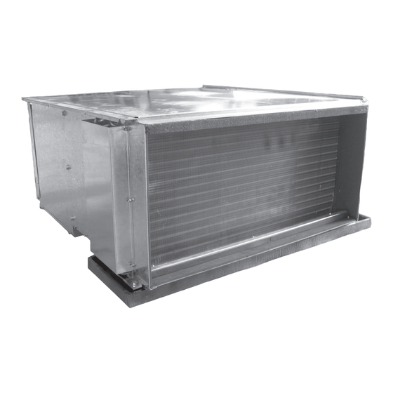
- Page 1 TRANE Installation Operation Maintenance Commercial Chilled Water Blower Coil Unit, FWDP Models FWDP 008 FWDP 024 FWDP 014 FWDP 028 FWDP 018 FWDP 032 FWDP-SVX01A-E4 (June 08)
- Page 2 TRANE ®...
-
Page 3: General Information
This manual covers the installation, operation and maintenance of the to be met in connection with Trane FWDD Chilled Water Blower Coil installation. Should further information units. These new air handler models be desired or should particular... -
Page 4: Table Of Contents
TRANE ® Content General Information Model Nomenclature General Data Dimensional Data Unit Installation Wiring Diagrams Unit Installation... -
Page 5: Model Nomenclature
® TRANE FWDP MODEL NOMENCLATURE... -
Page 6: General Data
TRANE ® General Data FWDP, 008, 014, 018, 024, 028, 032 FWDP008 FWDP014 FWDP018 FWDP024 FWDP028 FWDP032 Cooling coil unit Tube size, OD Face area 0.26 0.26 0.33 0.46 0.62 0.67 1” (25mm) BSPT Male THD Water in/out size 3/4" (19mm) BSPT Male THD... -
Page 7: Dimensional Data
® TRANE Dimensional Data FWDP 008/014/018/024/028/032 Table 1: - Fan Coil Dimensions MODEL 008/014 669.5 703.5 847.5 881.5 1148 1182.5 1216.5 1524 1558.5 1592.5 1651 1685.5 1719.5 MODEL 4 ROWS 3 ROWS 6 ROWS 008/014 Note: - Dimensions are in mm. -
Page 8: Unit Installation
TRANE ® Unit Installation Figure 1 WARNING: WARNING: OPEN AND ON SITE LOCK UNIT DISCONNECT TO LIFTING EQUIPMENT MUST PREVENT INJURY OR DEATH BE CAPABLE OF LIFTING THE FROM ELECTRIC SHOCK OR WEIGHT OF THE UNIT WITH CONTACT WITH MOVING... - Page 9 ® TRANE Unit Installation The unit should be installed for Figure 2 horizontal application only. Suspend the Drain Pan Trapping for unit under unit using the factory-provided threaded Prositive Pressure mounting holes on top of the unit. This is usually accomplished through the use of spring or rubber isolators, which are to be furnished by the installer.
- Page 10 TRANE ® Unit Installation 1.Verify that the unit electrical power is disconnected. 2.Inspect all field wiring connections. All connections should be clean and tight. 3.Inspect unit suspension arrangement(s). Ground must comply with all applicable codes. 4.Inspect unit suspension arrangement (if used). Unit position must be secure.
-
Page 11: Wiring Diagrams
® TRANE Wiring Diagram... -
Page 12: Unit Installation
TRANE ® Unit Installation Maintenance Contract Training It is strongly recommended that you The equipment described in this sign a maintenance contract with your manual is the result of many years of local Service Agency. This contract research continuous provides regular maintenance of your developement. - Page 13 Stocking Location Malaysia Trane has a policy of continuous product and product data improvement and reserves the right to For more information, contact your local district office change design and specifications without notice. Only qualified technicians should perform the installation...
Need help?
Do you have a question about the FWDP Series and is the answer not in the manual?
Questions and answers