Table of Contents
Advertisement
Quick Links
Chipsmall Limited consists of a professional team with an average of over 10 year of expertise in the distribution
of electronic components. Based in Hongkong, we have already established firm and mutual-benefit business
relationships with customers from,Europe,America and south Asia,supplying obsolete and hard-to-find components
to meet their specific needs.
With the principle of "Quality Parts,Customers Priority,Honest Operation,and Considerate Service",our business
mainly focus on the distribution of electronic components. Line cards we deal with include
Microchip,ALPS,ROHM,Xilinx,Pulse,ON,Everlight and Freescale. Main products comprise
IC,Modules,Potentiometer,IC Socket,Relay,Connector.Our parts cover such applications as commercial,industrial,
and automotives areas.
We are looking forward to setting up business relationship with you and hope to provide you with the best service
and solution. Let us make a better world for our industry!
Contact us
Tel: +86-755-8981 8866 Fax: +86-755-8427 6832
Email & Skype: info@chipsmall.com Web: www.chipsmall.com
Address: A1208, Overseas Decoration Building, #122 Zhenhua RD., Futian, Shenzhen, China
Advertisement
Table of Contents

Related Manuals for VTI SCA3000 DEMO KIT

Summary of Contents for VTI SCA3000 DEMO KIT
- Page 1 Chipsmall Limited consists of a professional team with an average of over 10 year of expertise in the distribution of electronic components. Based in Hongkong, we have already established firm and mutual-benefit business relationships with customers from,Europe,America and south Asia,supplying obsolete and hard-to-find components to meet their specific needs.
- Page 2 Doc.Nr. 8259300.11 SCA3000 DEMO KIT User Manual...
-
Page 3: Table Of Contents
SCA3000 DEMO KIT User Manual TABLE OF CONTENTS 1 Introduction .........................3 2 Quick start for using the SCA3000 DEMO KIT ..............3 3 Hardware..........................4 4 GUI software ........................4 Resetting GUI and µC ......................11 Uninstalling the GUI and USB driver..................11 5 Advanced data logging.....................11 6 SCA3000 current consumption measurement with DEMO KIT ........13... -
Page 4: Introduction
NOTICE, if you have already installed the SCP1000 demo to your computer, please check that the latency timer parameter is 5 ms. In case the latency timer value is greater than 5 ms, the SCA3000 DEMO KIT GUI will not work (more detailed instructions in section 9) 4. -
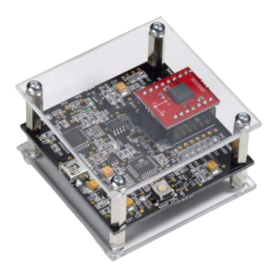
Page 5: Hardware
SCA3000 DEMO KIT User Manual Hardware The SCA3000 DEMO KIT USB interface board (black PWB) and SCA3000 PWB (red PWB) are shown in Figure 1. The USB interface card converts the USB interface to SPI or I C interface. SCA3000 sensor is soldered on PWB which is connected to interface board. - Page 6 SCA3000 DEMO KIT User Manual Screen capture of the GUI is presented in Figure 2. Figure 2. SCA3000 DEMO KIT Graphical User Interface Table 1. The numbered items in Figure 2. Item Description Temperature display, if temperature information is available for the sensor.
- Page 7 SCA3000 DEMO KIT User Manual If more than one USB serial port devices are connected to PC, user must select the correct USB SERIAL PORT from pop-up window (Figure 3). If user does not know the correct USB serial port number, please...
- Page 8 SCA3000 DEMO KIT User Manual The red led in the lower left corner in Figure 6 indicates the detected motion. By pressing the red led the interrupt is cleared by reading the INT_STATUS register. The INT_STATUS register contains the information of the interrupt cause. In Figure 6 Y- and Z-axis acceleration triggered the motion detector in previous time.
- Page 9 SCA3000 DEMO KIT User Manual 3D, 3 dimensional display with projections of each axis acceleration, see Figure 8. The minimum and maximum resultant accelerations as well as the current resultant acceleration are displayed on the right side of the graph. Minimum and maximum displays can be cleared by pressing the "Reset"...
- Page 10 SCA3000 DEMO KIT User Manual REGISTER CONFIG display offers user access in to SCA3000 sensor internal registers. Registers can be read and written. The written data format can be changed between binary and hexadecimal by pressing the "Bits / Hex" button.
- Page 11 This information is needed if the SCA3000 DEMO KIT is used without the GUI software, see further details from section 5. In this example the SCA3000 DEMO KIT uses COM4 serial port. Figure 12. Setup display. RESET DEMO initialises the GUI software.
-
Page 12: Resetting Gui And Μc
“Transfer” pull down menu → “Capture Text…” → “Stop” Macro language is used to control the SCA3000 DEMO KIT. It can be also used to configure the SCA3000 sensor. For more detailed information of macro language, please refer to “SCA3000 DEMO KIT macro language description 8259200”. - Page 13 If the pre-configured HyperTerminal connection is not available (the CD-ROM), the HyperTerminal connection can be opened also from: → Start → Programs → Accessories → Communications → HyperTerminal The communication settings are presented in Table 2 below Table 2. SCA3000 DEMO KIT serial communication settings. Parameter Value Bits per second...
-
Page 14: Sca3000 Current Consumption Measurement With Demo Kit
The offset current consumption of the DEMO KIT hardware depends on used serial communication (SPI vs. I C). The offset current consumption according to serial communication type is presented in Table 3 below. Table 3. Offset current consumption of the SCA3000 DEMO KIT HW. Serial interface Offset current consumption ~950 µA (V... -
Page 15: Usb Interface Board Circuit Diagram
SCA3000 DEMO KIT User Manual USB interface board circuit diagram SCA3000 demo USB interface board circuit diagram is presented in following pages. Figure 16. SCA3000 DEMO KIT USB interface board circuit diagram (sheet USB). VTI Technologies Oy 14/21 www.vti.fi Doc.Nr. 8259300.11... - Page 16 SCA3000 DEMO KIT User Manual Figure 17. SCA3000 DEMO KIT USB interface board circuit diagram (sheet µC). VTI Technologies Oy 15/21 www.vti.fi Doc.Nr. 8259300.11 Rev.0.11...
- Page 17 SCA3000 DEMO KIT User Manual Figure 18. SCA3000 DEMO KIT USB interface board circuit diagram (sheet power). VTI Technologies Oy 16/21 www.vti.fi Doc.Nr. 8259300.11 Rev.0.11...
-
Page 18: Usb Interface Board Pwb Layout
SCA3000 DEMO KIT User Manual USB interface board PWB layout SCA3000 DEMO KIT USB interface board PWB layout and silkscreen is presented below. Figure 19. SCA3000 DEMO KIT USB interface board PWB layout. Figure 20. SCA3000 DEMO KIT USB interface board silkscreen. -
Page 19: Troubleshooting
DELL laptops (Latitude D600, D610, D410) and desktop PCs with Win2000 and WinXP operating system. If the SCA3000 DEMO KIT does not work properly or it’s operation is limited, the following items may help to sort the problems out: •... - Page 20 SCA3000 DEMO KIT User Manual VTI Technologies Oy 19/21 www.vti.fi Doc.Nr. 8259300.11 Rev.0.11...
-
Page 21: Known Issues
SCA3000 DEMO KIT User Manual 9.1 Known Issues 9.1.1 Floating SCA3000 CLK-pin With MCU software version 0.9.95 the CLK-pin of SCA3000 (pin #4) is configured to floating instead of GND. SCA3000 will operate normally, but floating the CLK-pin may cause bigger current consumption values for SCA3000 than normally. -
Page 22: Document Revision History
SCA3000 DEMO KIT User Manual 10 Document Revision History Version Date Change Description 0.06 19.04.2006 Updated: - document template, minor language corrections 0.07 12.05.2006 Updated: - USB interface board updated (VTI29393B0), minor changes Current consumption measurement (section 6) 0.08 15.06.2006 GUI software version updated from version 0.16.4 to version 1.0 (visual update)
Need help?
Do you have a question about the SCA3000 DEMO KIT and is the answer not in the manual?
Questions and answers