Table of Contents
Advertisement
Quick Links
Advertisement
Table of Contents

Subscribe to Our Youtube Channel
Related Manuals for RCT Power Power Sensor 50

Summary of Contents for RCT Power Power Sensor 50
- Page 1 MANUAL Power Sensor 50 / 100...
- Page 2 Copyright © 2022 RCT Power GmbH. All rights reserved. This user manual may only be reprinted or copied in whole or in part with the express, written approval of RCT Power GmbH. Any type of reproduction, distribution, translated, or transmitted in any form or by any means, electronic or mechanical, including photocopying, recording, or storing in any information storage and retrieval system, without an authorized by RCT Power GmbH represents a violation of the applicable copyright laws and will be prosecuted.
-
Page 3: Table Of Contents
Table of contents ABOUT THIS DOCUMENT............................. 1 SAFETY INSTRUCTIONS ................FEHLER! TEXTMARKE NICHT DEFINIERT. PRODUCT INTRODUCTION ..........................3 CONNECTION OF POWER SENSOR ........................6 TROUBLESHOOTING ............................10 DISCONNECT THE SYSTEM FROM THE POWER SUPPLY ..................10 DISPOSAL ................................11 DISCLAIMER ..............................11 TECHNICAL DATA .............................. -
Page 4: About This Document
This document is valid for Power Sensor 50 / 100. Power Sensor 50 / 100 will be referred to as “current sensor”, “device” or “product” hereinafter unless specified otherwise. This setup manual contains a general instruction required for installing, wiring, commissioning and operating the Power Sensor 50 / 100. -
Page 5: Safety Instructions
They know and use the appropriate personal protective equipment. Safety precautions The Power Sensor 50 / 100 has been designed and tested strictly according to the international safety regulations. All safety instructions related to the electrical and electronic device must be complied with during installation, operation and maintenance. -
Page 6: Product Introduction
Intended usage The Power Sensor 50 / 100 is used to detect the grid power feed-in or grid power consumption, at the same time the household power is determined. The split core sensors allow easy use and installation without the separation of the current circuit. - Page 7 Inspect the Power Sensor unit for visible damages. Contact your supplier if the delivery is incomplete or damaged. Do not install, connect and operate the Power Sensor, if any damage was detected. Fig. 3-2.1 Delivery contents of Power Sensor 50 / 100 Item Description...
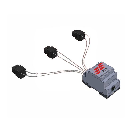
- Page 8 Product appearance Power Sensor 50 / 100 Item Description Current loop – interface, communication to the Power Storage. Split core – interface. Split core current sensors 50A[Power sensor 50], 200A[Power sensor 100].. 3.2.3 Name plate Item Description Serial number Technical data...
-
Page 9: Connection Of Power Sensor
4 Connection of Power Sensor Following tasks to start the Power Sensor • 4.1 Disconnecting from voltage • 4.2 Power Sensor mounting • 4.3 Split core sensors installation • 4.4 Connection to Power Storage DC • 4.5 Connection to Power Storage AC •... - Page 10 Power Sensor mounting Place the Power Sensor on a top-hat rail in the service entrance box. Split core sensors installation Click the three current sensors around the L1, L2 and L3 wires in the service entrance box (the order and direction of the current sensors installation is not important).
- Page 11 Connection to Power Storage DC 4.0 – 6.0 Unscrew and remove cover of inverter. Open cable gland and feed cables trough the holes next to the battery inputs. Connect the Power Sensor to the interface “C” on BPM board of the Power Storage via patch cable, as shown: At last close the cover of the inverter.
- Page 12 Should it be necessary to rearrange the power sensor for some reason (rewiring or similar), please proceed as follows: Sensor Configuration in operation mode: Step Description Start „RCT Power App“ and connect to the device. Continue with Device → Settings → Device settings (scroll down) → Power Sensor tuning (scroll down) Remove the hook at „Current sensors are tuned“...
-
Page 13: Troubleshooting
5 Troubleshooting Possible errors that occur can be read out via the existing display or also the RCT Power App. A detailed list of errors and possible remedies can be found in the user manual. Remote access is also possible via the RCT portal. The software version of your unit is also shown on the display or in the RCT Power App. -
Page 14: Disposal
RCT Power GmbH. RCT Power GmbH does not accept any guarantee for damage due to faulty or lost data, due to incorrect operation or malfunction of the inverter, the software, additional devices or PCs. -
Page 15: Technical Data
9 Technical Data Power Sensor Order Number 310-0001 310-0002 GENERAL Maximum current 3 x 50A 3 x 100A Accuracy 1,5 % Dimensions evaluation unit (height x width x depth) 91 x 72 x 44 mm Dimensions current sensors (height x width x depth) 41 x 26 x 26 mm 67 x 51 x 41 mm Current sensor cable length Max. - Page 16 RCT Power GmbH 1/2022 Line Eid Str. 1 78467 Constance, Germany Tel.: +49 (0)7531 996 77-0 Mail: info[at]rct-power.com Internet: www.rct-power.com...
Need help?
Do you have a question about the Power Sensor 50 and is the answer not in the manual?
Questions and answers