Table of Contents
Advertisement
Preface
Thank you for purchasing VD520 Series Inverters!
VD520 is a high-performance vector control inverter developed by VicRuns. Adopting advanced
vector control algorithm, it is widely used for asynchronous motor speed control. Through its
integrated EMC design and with optimized PWM control technique to meet users' demand on
environmental requirement such as low-noise in application places and low EMI. It has perfect
anti-tripping control and good adaptive ability to bad power grid, temperature, humidity and dust, in
order to satisfy various sophisticated requirement under high precision drive applications, thus to
satisfy users expectation of higher reliability and stronger adaptability to environment of their
equipment, achieving industry specialization and personalized motor drive and control system
solution.
VD520 series high performance vector control inverter has following outstanding features:
1. Various control method
Supporting control method: SVC, V/F control.
2. Leading vector control algorithm
Optimized sensorless vector control has better low speed stability, stronger low frequency load
capacity, supporting speed control and torque control.
3. Support multi-function I/O extension and multi-function MFI extension port
Multi-function I/O extension card, multi-function MFI extension port can connect related extension
function unit defined by manufacturer.
This manual provides the related issues: user installing and site wiring, quick debug, parameters
setting, failure diagnose and eliminate and daily maintenance and correlation matters. Please read
this manual to make sure you can install, use and maintain the inverter correctly, then play their
superior performance.
Please send this manual to the user or maintainer of this inverter, and properly kept.
Unpacking and Inspection:
Every inverter has been inspected rigorously before shipping.
Please confirm carefully when unpacking the packing carton:
● Check if any damage signs of the product and its package.
● Check if the model and inverter rated values on the nameplate are the same as stated on your order
and user manual.
● The box contains the inverter, manufacturer certificate, user manual.
If the product is damaged during transportation, or there is any omission or damage, please contact
our company or your local supplier immediately.
First time use suggests:
The users who use this product for the first time shall read this manual carefully. For any doubt on
certain functions and performances, please contact the technical support personnel of our company
for help, so as to use this product properly. With commitment to the constant improvement of the
inverter products, our company may change the information provided without additional notice.
VD520 series inverter is confirmed to below international standard, has passed the CE certification.
IEC/EN 61800-5-1: 2003 adjustable speed electric drive system safety regulation requirements;
IEC/EN 61800-3: 2004 adjustable speed electric drive system: part 3: product EMC standard and its
specific test method;
IEC/EN61000-2-1, 2-2, 3-2, 3-3, 4-2, 4-3, 4-4, 4-5, 4-6; EMC international and EU standard .
Advertisement
Table of Contents

Related Manuals for Vicruns VD520 Series


Summary of Contents for Vicruns VD520 Series
- Page 1 With commitment to the constant improvement of the inverter products, our company may change the information provided without additional notice. VD520 series inverter is confirmed to below international standard, has passed the CE certification. IEC/EN 61800-5-1: 2003 adjustable speed electric drive system safety regulation requirements;...
-
Page 3: Table Of Contents
Contents Chapter 1 Safety and Precautions ......................- 1 - 1.1 Safety Definition ........................... - 1 - 1.2 Safety Precautions ..........................- 1 - 1.3 General Precautions ..........................- 3 - Chapter 2 Product Information ........................- 6 - 2.1 Designation Rules ..........................- 6 - 2.2 Nameplate ............................. - Page 4 Chapter 7 EMC Guide ..........................- 190 - 7.1 Definition............................- 190 - 7.2 EMC Standard Introduction ......................- 190 - 7.3 EMC Guide ............................- 190 - Chapter 8 Fault Shooting and Solutions ....................- 192 - 8.1 Fault Alarm and Countermeasures ....................- 192 - 8.2 Common Faults and Solutions......................
-
Page 5: Chapter 1 Safety And Precautions
VD520 Series Inverter User Manual Safety and Precautions Chapter 1 Safety and Precautions 1.1 Safety Definition During the installation, commissioning and maintenance of the system, please make sure to follow the safety and precautions of this chapter. In case of a result of illegal operations, caused any harm and losses is nothing to do with the manufacturer. - Page 6 Safety and Precautions VD520 Series Inverter User Manual ● When two inverters are installed in the same cabinet, arrange the installation positions properly to ensure normal cooling effect, keep the cabinet with good ventilation. 1.2.3 At Wiring DANGER ● Wiring must be performed only by qualified personnel under instructions described in this manual.
-
Page 7: General Precautions
VD520 Series Inverter User Manual Safety and Precautions 1.2.6 During Operation DANGER ● Do not touch the cooling fan or braking resistor etc, otherwise may cause personal injury! ● Do not do inspection while inverter run, except for professional technician, otherwise may cause inverter damaged or personal injury. - Page 8 Safety and Precautions VD520 Series Inverter User Manual 1.3.5 Regarding Motor Heating and Noise Inverter output voltage is PWM wave, with some higher harmonic, so motor temperature rising, noise and vibration should increase a little comparing with power frequency, which is normal.
- Page 9 VD520 Series Inverter User Manual Safety and Precautions damage or performance reduce. - 5 -...
-
Page 10: Chapter 2 Product Information
Product Information VD520 Series Inverter User Manual Chapter 2 Product Information 2.1 Designation Rules VD520-4T-11GB/15PB Vicruns series Voltage level 220V Adaptable moter power Brake unit G type 11kW moter B: Including brake unit 220V None P type 15kW moter 380V Fig 2.1-1 Designation Rules... - Page 11 VD520 Series Inverter User Manual Product Information Three-phase Power supply:380V, 50/60Hz VD520-4T-0.7GB 0.75 VD520-4T-1.5GB VD520-4T-2.2GB VD520-4T-3.7GB 10.5 VD520-4T-5.5GB VD520-4T-5.5PB 14.6 13.0 VD520-4T-7.5GB VD520-4T-7.5PB 11.0 20.5 17.0 VD520-4T-11GB VD520-4T-11PB 17.0 26.0 25.0 11.0 VD520-4T-15GB VD520-4T-15PB 21.0 35.0 32.0 15.0 VD520-4T-18.5G VD520-4T-18.5PB 24.0...
-
Page 12: Product Specifications
Product Information VD520 Series Inverter User Manual 2.4 Product Specifications Table 2-2 Product technical specification Item Specifications Grade of rated voltage is 220V or 380V: voltage continued Rated input fluctuation±10%, brief fluctuation:-15~+10%, voltage voltage imbalance rated<3%, aberration rate meet IEC61800-2 requirements. - Page 13 VD520 Series Inverter User Manual Product Information Jogging frequency range: 0.00Hz~max output frequency, Jogging control jog Acceleration/down time 0.0s~3600.0s. Easy PLC, Via built-in PLC or control terminal can realize max 16 multi-stage speed stage speed run. Built-in PID Can realize process control conveniently.
-
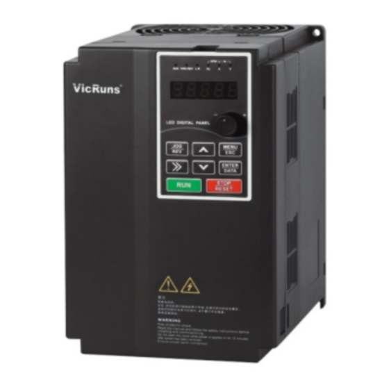
Page 14: Physical Appearance And Main Structure Diagram
Product Information VD520 Series Inverter User Manual LED display Can display 5 parameters Display and Motor short-circuit detection at power-on, input/output Keypad Protection phase loss protection, overcurrent protection, Operation function overvoltage protection, undervoltage protection, overheat protection and overload protection etc. -
Page 15: Product Appearance And Installation Dimension
VD520 Series Inverter User Manual Product Information 2.6 Product Appearance and Installation Dimension Fig 2.6-1Schematic Diagram for Physical Dimensions and Mounting Dimensions (below 7.5kW) Fig 2.6-2 Schematic Diagram for Physical Dimensions and Mounting Dimensions (11kW~110kW) Fig 2.6-3 Schematic Diagram for Physical Dimensions and Mounting Dimensions (up 132 kW) - Page 16 Product Information VD520 Series Inverter User Manual Diameter Weight Mounting Physical Dimensions ( mm) Mounting Hole (mm) Model Hole (mm) Single-phase 220V, 50/60Hz VD520-2S-0.7GB VD520-2S-1.5GB 106.5 VD520-2S-2.2GB VD520-2S-3.7GB VD520-2S-5.5GB Three-phase 380V, 50/60Hz VD520-4T-0.7GB VD520-4T-1.5GB 106.5 VD520-4T-2.2GB VD520-4T-3.7GB/5.5PB VD520-4T-5.5GB/7.5PB VD520-4T-7.5GB/11PB VD520-4T-11GB/15PB VD520-4T-15GB/18.5PB...
-
Page 17: Physical Dimensions Of External Keyboard
VD520 Series Inverter User Manual Product Information VD520-4T-220G/250P VD520-4T-250G/280P 1000 1450 VD520-4T-280G/315P VD520-4T-315G/355P VD520-4T-355G/400P VD520-4T-400G/450P 1300 1270 1240 1750 VD520-4T-450G/500P VD520-4T-500G/560P 2.7 Physical Dimensions of External Keyboard 2-M4 Physical Dimensions of Keyboard Physical Dimensions of Keyboard holder Fig 2.7-1 External keyboard and holder dimension 78.5... -
Page 18: Braking Unit Model Selection Guide
Product Information VD520 Series Inverter User Manual J3 J4 485+ 485- 5/10V HDI1 OPEN +24V T1/A T1/B T1/C COM HDO1 T2/A T2/C ● This inverter keyboard can be directly connected. ● A holder can be added to keyboard, but need to order separately. - Page 19 VD520 Series Inverter User Manual Product Information ≥65Ω VD520-4T-7.5GB/11PB 500W ≥43Ω VD520-4T-11GB/15PB 800W No special Internal instructions ≥32Ω VD520-4T-15GB/18.5PB 1000W ≥25Ω VD520-4T-18.5G/22P 1300W ≥26.5Ω VD520-4T-22G/30P 4.4kW ≥19.4Ω VD520-4T-30G/37P External VDBU-4T-70G ≥15.8Ω VD520-4T-37G/45P 7.4kW ≥13Ω VD520-4T-45G/55P ≥10.6Ω VD520-4T-55G/75P 11kW External VDBU-4T-110G ≥7.8Ω...
-
Page 20: Routine Repair And Maintenance Of Inverter
Product Information VD520 Series Inverter User Manual 2.9 Routine Repair and Maintenance of Inverter The influence of the ambient temperature, humidity, dust and vibration will cause the aging of the devices in the inverter, which may cause potential fault of the inverter or reduce the service life of the inverter. -
Page 21: Warranty Introduction
VD520 Series Inverter User Manual Product Information WARNING ● In general condition the inverter cooling fan need to replace for every 2-3 years. ● In general condition the big capacity electrolytic capacitor of inverter need to replace for every 4-5 years. -
Page 22: Chapter 3 Mechanical And Electrical Installation
Mechanical and Electrical Installation VD520 Series Inverter User Manual Chapter 3 Mechanical and Electrical Installation 3.1 Installation Environment The ambient temperature exerts great influences on the service life of the inverter and is not allowed to exceed the allowable temperature range (-10 ℃ Celsius to 40℃ Celsius). -
Page 23: Removing And Mounting The Cover Plate And Keyboard
VD520 Series Inverter User Manual Mechanical and Electrical Installation 3.3 Removing and Mounting the Cover Plate and Keyboard Fig 3.3-1 Removing and mounting the keyboard diagram Disassembly of control panel: put the middle finger on upper part of control panel, lightly press the upper clip and pull out. -
Page 24: Inverter And External Electrical Parts Connection
Mechanical and Electrical Installation VD520 Series Inverter User Manual Bottom Corver plate Fig 3.3-3 Removing and installing the cover plate of sheet-metal enclosure Disassembly and installation of sheet-metal enclosure: with cross screwdriver to screw off the two screws at the bottom of the undercover plate, then loosen the two screws at the top of the undercover plate, pull-down the undercover plate can be disassemble, reverse order the undercover plate can be install. - Page 25 VD520 Series Inverter User Manual Mechanical and Electrical Installation Table 3-1 the peripheral devices Must install the isolation switch device such as a obvious segmentation between the grid and frequency inverter, and ensure the personal safety when equipment maintenance. Breaker The capacity of breaker is 1.5~2 time of frequency inverter rated...
- Page 26 Mechanical and Electrical Installation VD520 Series Inverter User Manual The memory of the leakage current of inverter, in order to ensure the safety of the inverter and motor must grounding, grounding resistance should be less than 10Ω. The grounding wire should be as short as possible, wire diameter should conform to table 3-3 standard.
- Page 27 VD520 Series Inverter User Manual Mechanical and Electrical Installation VD520-2S-2.2GB VD520-2S-3.7GB VD520-2S-5.5GB Three-phase 380V 50/60Hz VD520-4T-0.7GB VD520-4T-1.5GB VD520-4T-2.2GB VD520-4T-3.7GB/5.5PB VD520-4T-5.5GB/7.5PB VD520-4T-7.5GB/11PB VD520-4T-11GB/15PB VD520-4T-15GB/18.5PB VD520-4T-18.5G/22P VD520-4T-22G/30P VD520-4T-30G/37P VD520-4T-37G/45P VD520-4T-45G/55P VD520-4T-55G/75P VD520-4T-75G/90P VD520-4T-90G/110P VD520-4T-110G/132P VD520-4T-132G/160P VD520-4T-160G/185P VD520-4T-185G/200P VD520-4T-200G/220P 150*2 150*2 VD520-4T-220G/250P 150*2...
- Page 28 Mechanical and Electrical Installation VD520 Series Inverter User Manual Table 3-5 Selection table of input/output AC Reactor, DC reactor Input AC Reactor Output AC Reactor DC Reactor Inverter Capacity(kW) Current Inductance Current Inductance Current Inductance (mH) (mH) (mH) VD520-4T-0.7GB VD520-4T-1.5GB VD520-4T-2.2GB...
-
Page 29: Standard Wiring Diagram
VD520 Series Inverter User Manual Mechanical and Electrical Installation 3.5 Standard Wiring Diagram 3.5.1 Standard Wiring Diagram for Single-phase 220V Inverter Brake unit VicRuns Collector output FWD/Stop +24V REV/Stop +24V COM HDO1 Free stop High pulse output Fault reset HDI1... - Page 30 Mechanical and Electrical Installation VD520 Series Inverter User Manual 3.5.2 Standard Wiring Diagram for Three-phase and Lower than 15kW Inverter: Brake unit L1/R L2/S L3/T VicRuns Collector output FWD/Stop REV/Stop +24V HDO1 +24V COM Free stop High pulse output Fault reset...
-
Page 31: Main Circuit Terminals
VD520 Series Inverter User Manual Mechanical and Electrical Installation 3.5.3 Standard Wiring Diagram for Three-phase and High than 18.5kW Inverter: Brake unit VDBU L1/R L2/S L3/T VicRuns Collector output FWD/Stop +24V REV/Stop HDO1 +24V COM Free stop High pulse output... - Page 32 Mechanical and Electrical Installation VD520 Series Inverter User Manual PB P+ Three phrase Three phrase Brake unit motor power Fig 3.6-2 Wiring diagram of main circuit of three-phase and lower than 2.2kW inverter 3.6.1.3 Wiring Diagram of Main Circuit of Three-phase 3.7kw-15kw Inverter...
- Page 33 Mechanical and Electrical Installation DANGER ● The voltage class of VD520 series inverter 3phase power has two grades: 220V, 380V, before connecting power, please make sure the power class on inverter nameplate is the same with the accessing power. Otherwise do not connect.
-
Page 34: Control Circuit Terminal
Mechanical and Electrical Installation VD520 Series Inverter User Manual 3.7 Control Circuit Terminal 3.7.1 Control Terminals and Functional J3J4 485+ 485- 5/10V AI2 AO1 HDI1 DI2 OPEN +24V T1/A T1/B T1/C DI5 COM HDO1 DO1 PE GND T2/A T2/C Fig 3.7-1 Diagram of main control board and function extension card connection 3.7.2 Description of Control Circuit Terminal... - Page 35 VD520 Series Inverter User Manual Mechanical and Electrical Installation 1. Connect to 24V by default, J14 jumper on main control board to select +24V or COM connection. External Power Supply OPEN power input 2. When external power is used to drive...
- Page 36 Mechanical and Electrical Installation VD520 Series Inverter User Manual 1. Optical coupling isolation, dual polarity open collector output; Digital output DO1-COM 2. Pull-up voltage range: 5V~24V (pull-up resistance range: 0.48kΩ~10kΩ); 3. Output current range: 2mA~50mA. 1. When used as general digital output, same function as DO1;...
- Page 37 VD520 Series Inverter User Manual Mechanical and Electrical Installation When jump cap plug connect to A, AI2 terminal select A terminal DC0/4mA-20mA current signal output When jump cap plug connect to V, AI2 terminal select DC0V-10V V terminal voltage output...
- Page 38 Mechanical and Electrical Installation VD520 Series Inverter User Manual +24V +24VOPEN COM +24V Fuse Protector OPEN DC24V HDI1、 3.3k DI1~DI5 VicRuns External circuit Internal circuit Fig 3.7-3 Diagram of digital input terminal with external power connection Use external power(power must comply with UL CLASS 2 standard, a 4A fuse protector should be added between power and port), wiring diagram as Fig 3.7-3 showed.(take note to remove the...
- Page 39 VD520 Series Inverter User Manual Mechanical and Electrical Installation Cross in the same director or uind 2 to 3 cotis in the same director AI1、AI2 External analog 0.022uF50V source Ferite magenetic VicRuns ring Internal circuit External control Fig 3.7-6 Schematic diagram of analog input terminal cable jacket ferrite magnetic ring 3.7.5.3 Digital Output Terminal Using Internal Power Supply...
- Page 40 Mechanical and Electrical Installation VD520 Series Inverter User Manual DC 5~24V DO1、HDO1 Flyback Relay Diode VicRuns Internal circuit External control Fig 3.7-9 Schematic diagram of digital output terminal using external power 4.7kΩ HDO1 DC5~24V Digital Frequency VicRuns Internal circuit External control Fig 3.7-10 Schematic diagram of high speed pulse output using external power...
- Page 41 VD520 Series Inverter User Manual Mechanical and Electrical Installation DC0~20mA VicRuns Internal circuit Exteranl control Fig 3.7-12 Schematic diagram of terminal of analog output of current signal 3.7.5.6 Output Terminals of Relay +24V +24V Short-Circuit Plate or Wire T1/A Halt Indicate...
-
Page 42: Chapter 4 Operation And Display
Operation and Display VD520 Series Inverter User Manual Chapter 4 Operation and Display 4.1 Introduction to Operation and Display Interface With the operation panel, it can perform such operations on the inverter as function parameter modification, inverter working status monitoring and inverter run control (startup and stop). - Page 43 VD520 Series Inverter User Manual Operation and Display This key is used to operate on the inverter in key Run key operation mode This key is used to stop in running state and it is limited Stop/Reset key by function code F7-01...
-
Page 44: Motor Parameter Self-Learning
Select vector control mode, before inverter operation, must input the parameter from the nameplate of the motor, VD520 series inverter will match standard motor parameter according to this message. Vector control mode is highly dependent on motor parameter, so to acquire good control performance, it needs correct motor parameter. -
Page 45: Password Setting
After self-learning, the function code recover to 0. 4.3 Password Setting The VD520 series inverter provides user password protection function. When FF-00 is set to non-zero value, it indicates the user password, and the password protection turns enabled after exiting the function code editing status. -
Page 46: Chapter 5 Function Parameter Table
Function Parameter Table VD520 Series Inverter User Manual Chapter 5 Function Parameter Table The symbols in the function table are described as follows: ○——It indicates that the parameter setup value can be modified when the inverter is in run state;... - Page 47 VD520 Series Inverter User Manual Function Parameter Table Auxiliary Frequency Same as F0-02(Main Frequency ◎ F0-04 Source A Source A Selection) Selection Unit’s digit: frequency source selection 0: Main frequency source A 1: Main auxiliary operation result(operational relationship is determined by ten Bits)
- Page 48 Function Parameter Table VD520 Series Inverter User Manual Frequency Upper ○ F0-13 0.00Hz~max frequency F0-10 0.00Hz Limit Offset Frequency Lower ○ F0-14 0.00Hz~frequency upper limit F0-12 0.00Hz Limit Frequency ● F0-15 Command 2: 0.01Hz Resolution Frequency Command 0: Running frequency ◎...
- Page 49 VD520 Series Inverter User Manual Function Parameter Table command binding frequency source selection, same as above Communication ● F0-23 0: Modbus Protocol Selection 0: Motor 1 ◎ F0-24 Motor Selection 1: Motor 2 1: G type (constant torque load model) ◎...
- Page 50 Function Parameter Table VD520 Series Inverter User Manual Voltage Rise Rate ○ F1-07 of Rotation Speed 0~1000 Tracking 0: Decelerate to stop ○ F1-08 Stop Mode 1: Coast to stop Initial Frequency of ○ F1-09 0.00Hz~max frequency 0.00Hz Stop DC Braking Waiting Time of ○...
- Page 51 VD520 Series Inverter User Manual Function Parameter Table 0: The whole is valid 1: Only overpressure stall enable effectively Over-excitation ◎ F1-24 Effective Range 2: Only deceleration process effectively 3: The whole is invalid Over-excitation ○ F1-25 0~200 Gain Over-excitation ○...
- Page 52 Function Parameter Table VD520 Series Inverter User Manual Model Rated Motor ◎ F2-05 1RPM~65535RPM Rotation Speed dependent 0.001Ω~65.535Ω (Inverter Asynchronous power≤55kW) Tune ◎ F2-06 Motor Stator 0.0001Ω~6.5535Ω (Inverter parameter Resistance power>55kW) 0.001Ω~65.535Ω (Inverter Asynchronous power≤55kW) Tune ◎ F2-07 Motor Rotor 0.0001Ω~6.5535Ω...
- Page 53 VD520 Series Inverter User Manual Function Parameter Table Vector Control Slip ○ F3-06 20%~200% 100% Gain Speed Loop Filter ○ F3-07 0.000s~0.100s 0.000s Time Constant 0: Encode F3-10 setting 1: AI1 2: AI2 3: AI3 Motor Torque 4: PULSE setting ○...
- Page 54 Function Parameter Table VD520 Series Inverter User Manual Max Weak ○ F3-20 1%~300% Magnetic Current Weak Magnetic ○ F3-21 Automatic Gain 10%~500% 100% Adjustment Weak Magnetic ○ F3-22 2~10 Integral Multiples Torque Boost ○ F3-23 0.0%~60.0% 10.0% Coefficient Torque Boost ○...
- Page 55 VD520 Series Inverter User Manual Function Parameter Table MS VF Frequency ◎ F4-06 F4-04~F4-07 0.00Hz Point 2 MS VF Voltage ◎ F4-07 0.0%~100.0% 0.0% Point 2 MS VF Frequency F4-05~Rated motor frequency ◎ F4-08 0.00Hz Point 3 (F2-04) MS VF Voltage ◎...
- Page 56 Function Parameter Table VD520 Series Inverter User Manual F5 Input Terminal Factory Function Parameter Name Setting Range Default Property Code Value 0: Two-line mode 1 1: Two-line mode 2 2: Three-line mode 1 Terminal ◎ F5-00 Command Mode 3: Three-line mode 2...
- Page 57 VD520 Series Inverter User Manual Function Parameter Table 27: Deceleration DC braking 28: External stop terminal 1 (Only effective for keypad control) 29: External stop terminal 2 (According to the deceleration time 4) 30: Emergency stop 31: PID pause 32: PID integral pause...
- Page 58 Function Parameter Table VD520 Series Inverter User Manual Unit’s digit: HDI1 0: High level effective DI1 Terminal Mode 1: Low level effective ◎ F5-11 Selection 2 0x0000 Ten’s digit: reserved Effectively Hundred’s digit: reserved Thousand’s digit: reserved ○ F5-12 DI Filter Time 0.000s~1.000s...
- Page 59 VD520 Series Inverter User Manual Function Parameter Table Corresponding ○ F5-23 Setting of AI Curve -100.0%~+100.0% 0.0% 1 Min Input AI Curve 1 Max ○ F5-24 F5-22~+10.00V 10.00V Input Corresponding ○ F5-25 Setting of AI Curve -100.0%~+100.0% 100.0% 1 Max Input ○...
- Page 60 Function Parameter Table VD520 Series Inverter User Manual F6 Output Terminal Factory Function Parameter Setting Range Default Property Code Name Value HDO1 0: HS Pulse output Terminals ○ F6-00 Output Mode 1: Switch signal output Selection HDO1 0: No output...
- Page 61 VD520 Series Inverter User Manual Function Parameter Table reached 31: Accumulative power-on time reached 32: Timing reached output 33: PLC circulation output 34: Frequency limit 35: Torque limit 36: Reverse running 37: AI1 input limit 38: AI1>AI2 39: Communication setting...
- Page 62 Function Parameter Table VD520 Series Inverter User Manual 9: Reserved 10: Length 11: Count value 12: Communication setting 13: Motor rotate speed 14: Output current (when≤55kW, 100.0% corresponding 100.00A; when>55kW, 100.0% corresponding 1000.00A) 15: Output voltage (100.0% corresponding 1000.00A) 16: Reserved HDO1 Output ○...
- Page 63 VD520 Series Inverter User Manual Function Parameter Table AO2 Output ○ F6-25 0.00s~10.00s 0.00s Filter Time HDO1 ○ F6-28 Disconnect 0.0s~3600.0s 0.0s Delay T1 Disconnect ○ F6-29 0.0s~3600.0s 0.0s Delay T2 Disconnect ○ F6-30 0.0s~3600.0s 0.0s Delay DO1 Disconnect ○...
- Page 64 Function Parameter Table VD520 Series Inverter User Manual Bit13: Length value Bit14: Load speed display BIT15: PID setting 0000~0xFFFF Bit00: PID feedback Bit01: PLC stage Bit02: PULSE input frequency (kHz) Bit03: Running frequency 2 (Hz) Bit04: Set torque (0.%) Bit05: Voltage before AI1 correction...
- Page 65 VD520 Series Inverter User Manual Function Parameter Table Display Parameters Load Speed ○ F7-07 Display 0.000s~6.5000 1.0000 Coefficient 0: 0 bit decimal place Load Speed 1: 1 bit decimal place ○ F7-08 Display Decimal 2: 2 bit decimal place Places...
- Page 66 Function Parameter Table VD520 Series Inverter User Manual Over current 0: Disabled ○ F8-10 Stall Proportion 1~1000 Gain Over current ○ F8-11 Stall Integral 0~1000 Gain Over current ○ F8-12 Stall Protection 100%~200% 160% Current Quick Start Over current ○...
- Page 67 VD520 Series Inverter User Manual Function Parameter Table Maximum 0: No limit Change of V/F ○ F8-28 Over Voltage 1~30000 Stall F9 Fault Record and Setting Factory Function Parameter Setting Range Default Property Code Name Value Fault Types for 0: No fault ●...
- Page 68 Function Parameter Table VD520 Series Inverter User Manual 36: User-defined fault 2 37: Offload 38: Fast current-limiting timeout 39: Switch motor in running 40~42: Reserved 43: Manufacturer defined fault Frequency Upon the Third ● F9-03 Time (Last Time) Fault Current Upon the Third Time ●...
- Page 69 VD520 Series Inverter User Manual Function Parameter Table Input Terminal State Upon the ● F9-16 Second Time Fault Output Terminal State Upon the ● F9-17 Second Time Fault Inverter State Upon the ● F9-18 Second Time Fault Power on Time Upon the ●...
- Page 70 Function Parameter Table VD520 Series Inverter User Manual Time Fault DO Action Selection 0: No action ○ F9-35 During the Fault 1: Action Automatic Reset Unit’s digit: motor overload (11) 0: Coast to stop 1: Stop according to stop mode 2: Continue to run Ten’s digit: input phase loss (13)
- Page 71 VD520 Series Inverter User Manual Function Parameter Table 2: Continue to run Ten’s digit: user-defined fault 1 (36) 0: Coast to stop 1: Stop according to stop mode 2: Continue to run Hundred’s digit: power on time reached (28) 0: Coast to stop...
- Page 72 Function Parameter Table VD520 Series Inverter User Manual Source 1: AI1 2: AI2 3: Reserved 4: PULSE setting 5: Communication setting 6: Multi-reference setting 7: Keypad potentiometer PID Digital ○ FA-01 0.0%~100.0% 50.0% Giving 0: A1 1: AI2 2: Reserved...
- Page 73 VD520 Series Inverter User Manual Function Parameter Table Proportion Gain ○ FA-15 0.0~100.0 20.0 Integral Time ○ FA-16 0.01s~10.00s 2.00s Differential Time ○ FA-17 0.000s~10.000s 0.000s 0: No switching PID Parameters 1: Switching through DI terminal ○ FA-18 Switching 2: Automatic switching according to...
- Page 74 Function Parameter Table VD520 Series Inverter User Manual 0: No operation when stop PID Stop ○ FA-29 Operation 1: Operation when stop The Lower Limit 0.0%: No limit Value of ○ FA-30 0.0.% Feedback when 0.1%~100.0% PID Action Fb Enhance Function Group...
- Page 75 VD520 Series Inverter User Manual Function Parameter Table Hopping ○ Fb-14 Frequency 0.01Hz~max frequency 0.01Hz Range Hopping Frequency 0: Disabled Whether Valid in ○ Fb-15 the Process of 1: Enabled Acceleration / deceleration Frequency ○ Fb-16 Detection Value 0.00Hz~max frequency 50.00Hz...
- Page 76 Function Parameter Table VD520 Series Inverter User Manual 0.0% (no detection) Output Current ○ Fb-27 200.0% Limit Exceed 0.1%~300.0% (rated motor current) Output Current Limit Exceed ○ Fb-28 0.00s~600.00s 0.00s Detection Delay Time Any Current ○ Fb-29 0.0%~300.0% (rated motor current) 100.0%...
- Page 77 VD520 Series Inverter User Manual Function Parameter Table Wakeup Dormancy frequency (Fb-44)~max ○ Fb-42 0.00Hz Frequency frequency (F0-10) Wakeup Delay ○ Fb-43 0.0s~6500.0s 0.0s Time Dormancy ○ Fb-44 0.00Hz~wakeup frequency (Fb-42) 0.00Hz Frequency Dormancy ○ Fb-45 0.0s~6500.0s 0.0s Delay Time Timing Braking ○...
- Page 78 Function Parameter Table VD520 Series Inverter User Manual Multi-reference ○ FC-01 -100.0%~100.0% 0.0% Multi-reference ○ FC-02 -100.0%~100.0% 0.0% Multi-reference ○ FC-03 -100.0%~100.0% 0.0% Multi-reference ○ FC-04 -100.0%~100.0% 0.0% Multi-reference ○ FC-05 -100.0%~100.0% 0.0% Multi-reference ○ FC-06 -100.0%~100.0% 0.0% Multi-reference ○...
- Page 79 VD520 Series Inverter User Manual Function Parameter Table Run Time of ○ FC-18 Simple PLC 0.0s (h)~6553.5s (h) 0.0s (h) Reference 0 Acceleration / Deceleration ○ FC-19 Time Selection of Simple PLC Reference 0 Run Time of ○ FC-20 Simple PLC 0.0s (h)~6553.5s (h)
- Page 80 Function Parameter Table VD520 Series Inverter User Manual Run Time of ○ FC-30 Simple PLC 0.0s (h)~6553.5s (h) 0.0s (h) Reference 6 Acceleration / Deceleration ○ FC-31 Time Selection of Simple PLC Reference 6 Run Time of ○ FC-32 Simple PLC 0.0s (h)~6553.5s (h)
- Page 81 VD520 Series Inverter User Manual Function Parameter Table Run Time of ○ FC-42 Simple PLC 0.0s (h)~6553.5s (h) 0.0s (h) Reference 12 Acceleration / Deceleration ○ FC-43 Time Selection of Simple PLC Reference 12 Run Time of ○ FC-44 Simple PLC 0.0s (h)~6553.5s (h)
- Page 82 Function Parameter Table VD520 Series Inverter User Manual Fd MODBUS Communication Factory Function Parameter Setting Range Default Property Code Name Value 0: 300BPS 1: 600BPS 2: 1200BPS 3: 2400BPS 4: 4800BPS ○ Fd-00 Baud Rate 5: 9600BPS 6: 19200BPS 7: 38400BPS...
- Page 83 VD520 Series Inverter User Manual Function Parameter Table Unit’s digit: 0: Not display A group Function Code 1: Display A group ○ FF-03 Display 0x11 Ten’s digit: Selection 0: Not display b group 1: Display b group 0: Can modify Function Code ○...
- Page 84 Function Parameter Table VD520 Series Inverter User Manual A0 Motor 1 Torque Control . Factory Function Parameter Setting Range Default Property Code Name Value Speed/Torque 0: Speed control ◎ A0-00 Control Mode 1: Torque control Selection 0: Digital setting (A0-02)
- Page 85 VD520 Series Inverter User Manual Function Parameter Table Max Frequency Digital Setting ○ A0-06 under the 0.00Hz~max frequency 50.00Hz Torque Control Reverse Torque Control ○ A0-07 Acceleration 0.00s~650.00s 0.00s Time Torque Control ○ A0-08 deceleration 0.00s~650.00s 0.00s Time Starting Torque ○...
- Page 86 Function Parameter Table VD520 Series Inverter User Manual Rotational Inertia ○ A0-17 0.00~10.00 0.00 Compensation Coefficient Rotational Inertia ○ A0-18 0.0%~50.0% 5.0% Compensation Upper Limit Rotational Inertia ○ A0-19 Compensation 0.00Hz~max frequency 10.00Hz Starting Frequency Lowest Resolution 0.00: Not limit ○...
- Page 87 VD520 Series Inverter User Manual Function Parameter Table 0: Random PWM invalid Random PWM ○ A1-05 1~10: PWM carrier frequency random Depth depth 0: Disabled Rapid Current ○ A1-06 Limiting Enable 1: Enabled Current ○ A1-07 Detection 0~100 Compensation 0: Not optimize SVC Optimize ○...
- Page 88 Function Parameter Table VD520 Series Inverter User Manual 0.001Ω~65.535Ω (Inverter Asynchronous power≤55kW) Tune ◎ A2-06 Motor Stator 0.0001Ω~6.5535Ω (Inverter parameter Resistance power>55kW) 0.001Ω~65.535Ω (Inverter Asynchronous power≤55kW) Tune ◎ A2-07 Motor Rotor 0.0001Ω~6.5535Ω (Inverter parameter Resistance power>55kW) 0.01mH~655.35mH (Inverter Asynchronous power≤55kW)
- Page 89 VD520 Series Inverter User Manual Function Parameter Table Speed Loop ○ A3-07 Filter Time 0.000s~0.100s 0.000s Constant 0: Encode F3-10 setting 1: AI1 2: AI2 3: AI3 Motor Torque 4: PULSE setting ○ A3-09 Upper Limit 5: Communication setting Source...
- Page 90 Function Parameter Table VD520 Series Inverter User Manual Max Weak ○ A3-20 Magnetic 1%~300% Current Weak Magnetic Automatic ○ A3-21 10%~500% 100% Adjustment Gain Weak Magnetic ○ A3-22 2~10 Integral Multiple Torque Boost ○ A3-23 0.0%~60.0% 10.0% Coefficient Torque Boost ○...
- Page 91 VD520 Series Inverter User Manual Function Parameter Table MS VF ◎ A4-04 Frequency Point 0.00Hz~F4-05 0.00Hz MS VF Voltage ◎ A4-05 0.0%~100.0% 0.0% Point 1 MS VF ◎ A4-06 Frequency Point F4-04~F4-07 0.00Hz MS VF Voltage ◎ A4-07 0.0%~100.0% 0.0%...
- Page 92 Function Parameter Table VD520 Series Inverter User Manual 0.0s~1000.0s VF Separation ○ A4-17 Voltage Fall 5.0s Remark: Indication the time that rated Time motor voltage drop to 0V b0 User Customize Function Code Factory Function Parameter Setting Range Default Property...
- Page 93 VD520 Series Inverter User Manual Function Parameter Table ○ b0-26 User Code 26 FF-06 ○ b0-27 User Code 27 FF-06 ○ b0-28 User Code 28 FF-06 ○ b0-29 User Code 29 FF-06 ○ b0-30 User Code 30 FF-06 ○ b0-31...
- Page 94 Function Parameter Table VD520 Series Inverter User Manual Unit’s digit: virtual VDI1 0: Disabled 1: Enabled Ten’s digit: virtual VDI2, same as Virtual VDI above ◎ b1-06 Terminal state 0x00000 Hundred’s digit: virtual VDI3, same as setting above Thousand’s digit: virtual VDI4, same as above Ten thousand’s digit: virtual VDI5,...
- Page 95 VD520 Series Inverter User Manual Function Parameter Table VDO4 Closing ○ b1-19 0.0s~3600.0s 0.0s Delay VDO5 Closing ○ b1-20 0.0s~3600.0s 0.0s Delay Unit’s digit: VDO1 0: Positive logic 1: Anti-logic VDO Output Ten’s digit: VDO2, same as above Terminal ○...
- Page 96 Function Parameter Table VD520 Series Inverter User Manual Corresponding Setting of AI ○ b2-03 Curve 4 -100.0%~+100.0% 30.0% Inflection Point 1 Input AI Curve 4 ○ b2-04 Inflection Point b2-00~b2-06 6.00V 2 Input Corresponding Setting of AI ○ b2-05 Curve 4 -100.0%~+100.0%...
- Page 97 VD520 Series Inverter User Manual Function Parameter Table AI1 Setting ○ b2-16 -100.0%~100.0% 0.0% Jump Point AI1 Setting ○ b2-17 0.0%~100.0% 0.5% Jump Range AI2 Setting ○ b2-18 -100.0%~100.0% 0.0% Jump Point AI2 Setting ○ b2-19 0.0%~100.0% 0.5% Jump Range...
- Page 98 Function Parameter Table VD520 Series Inverter User Manual AO1 Measured Factory ○ b3-15 6.000V~9.999V Voltage 2 Correction Target Voltage 1 Factory ○ b3-16 0.500V~4.000V Of AO2 Correction AO2 Measured Factory ○ b3-17 0.500V~4.000V Voltage 1 Correction AO2 Target Factory ○...
- Page 99 VD520 Series Inverter User Manual Function Parameter Table ● U0-17 PLC Stage Input PULSE ● U0-18 Frequency 0.01 kHz (kHz) Feedback ● U0-19 0.1Hz Speed (0.1Hz) ● U0-20 Setting Torque 0.1% AI1 Voltage ● U0-21 before 0.001V Correction AI2 Voltage ●...
- Page 100 Function Parameter Table VD520 Series Inverter User Manual VF Separation ● U0-40 Output Voltage Visual Display ● U0-41 DI Input State Visual Display ● U0-42 DO Input State Visual Display DI Function ● U0-43 State 1 (Function 01~40) Visual Display DI Function ●...
-
Page 101: Chapter 6 Parameter Description
VD520 Series Inverter User Manual Parameter Description Chapter 6 Parameter Description F0 Basic Function Led unit’s digit: motor 1 0: V/F control 1: SVC ◎ F0-00 Motor Control Mode 0x00 Led ten’s digit: motor 2 0: V/F control 1: SVC... - Page 102 Parameter Description VD520 Series Inverter User Manual 0: Digital setting(F0-09, UP/DOWN can be modified, no memory when power failure) 1: Digital setting(F0-09, UP/DOWN can be modified, memory when power failure) 2: AI1 3: AI2 Main Frequency 4: Reserved ◎ F0-02...
- Page 103 VD520 Series Inverter User Manual Parameter Description 100.0%, is refers to the relative maximum frequency F0-10 percentage. 6: MS reference Select MS reference operation mode, need through the digital quantity input DI terminal state of different combination, corresponding to different set frequency values. VD520 can set up more than 4 MS reference terminal, the 16 kinds of sate of 4 terminals by FC group function code corresponding to the arbitrary 16 “MS reference”, “MS reference”...
- Page 104 Parameter Description VD520 Series Inverter User Manual Unit’s digit: frequency source selection 0: Main frequency source A 1: Main auxiliary operation result(operational relationship is determined by ten Bits) 2: Main frequency source A switching with auxiliary frequency source B Frequency Source 3: Main frequency source A switching with ○...
- Page 105 VD520 Series Inverter User Manual Parameter Description In addition, when the frequency source selection for the main and auxiliary operation, can be set the offset frequency through F0-08, superimposed offset frequency on the main and auxiliary operation result in a flexible response to all kinds of needs.
- Page 106 Parameter Description VD520 Series Inverter User Manual Frequency Upper Frequency lower limit F0-14~max frequency ○ F0-12 50.00Hz Limit F0-10 Frequency Upper ○ F0-13 0.00Hz~max frequency F0-10 0.00Hz Limit Offset When the frequency upper limit for analog or PULSE setting, F0-13 as the offset of set value, the offset frequency and F0-11 set frequency upper limit value superposition, as the final frequency upper limit set value.
- Page 107 VD520 Series Inverter User Manual Parameter Description Deceleration time refers to the time required that frequency inverter from deceleration/deceleration reference frequency (F0-21) deceleration to zero frequency, as show in figure 6-1 in the t2. Output frequency(Hz) Acceleration/deceleration reference frequency Set frequency...
- Page 108 Parameter Description VD520 Series Inverter User Manual Unit’s digit: Operation panel command binding frequency source selection 0: No binding 1: Digital setting frequency 2: AI1 3: AI2 4: Reserved 5: PULSE setting Command Source 6: MS reference ○ F0-22 Bound Frequency...
-
Page 109: F1 Start/Stop Control Group
VD520 Series Inverter User Manual Parameter Description F1 Start/Stop Control Group 0: Direct start 1: Speed tracking restart ○ F1-00 Start Mode 2: Pre excitation start (AC asynchronous ) 0: Direct start If start dc braking time is set to 0, the frequency inverter starting run from start frequency. - Page 110 Parameter Description VD520 Series Inverter User Manual Starting DC Braking ◎ F1-03 Current/ Pre-excitation 0%~100% Current Starting DC Braking ◎ F1-04 Current/ Pre-excitation 0.0s~100.0s 0.0s Current Start the dc braking, generally used to make the running motor restart after stop. Pre excitation is used to make the asynchronous motor build magnetic field first then restart, improve the response speed.
- Page 111 VD520 Series Inverter User Manual Parameter Description Initial Frequency of Stop ○ F1-09 0.00Hz~max frequency 0.00Hz DC Braking Waiting Time of Stop DC ○ F1-10 0.0s~100.0s 0.0s Braking ○ F1-11 Stop DC Braking Current 0%~100% ○ F1-12 Stop DC Braking Time 0.0s~100.0s...
- Page 112 Parameter Description VD520 Series Inverter User Manual 0: Enabled Restart Selection Upon ○ F1-15 Power Failure 1: Disabled Waiting Time of Restart ○ F1-16 0.0s~60.0s 0.0s Upon Power Failure Used to run command source is terminal control. Enabled: when terminal run command has maintained, inverter will autostart after power on self-inspection normal and delay the time of F1-16.
- Page 113 VD520 Series Inverter User Manual Parameter Description Output frequency(Hz) Forward Reverse Dead-zone time Fig 6-3 Schematic diagram of forward/reverse dead-zoen time 0: Disabled Dynamic Braking ○ F1-22 Enable 1: Enabled ○ F1-23 Braking Usage Rate 0%~100% 100% Only be effective for the inverter that built-in braking unit.
- Page 114 Parameter Description VD520 Series Inverter User Manual Output frequency increase or decrease according to the S curve. S curve is used in the pace with gentle start or stop demand, such as elevator, conveyor belt, etc. Function code F1-28 and F1-29 respectively defined the time scale of inertial stage and finish stage of S curve acceleration/deceleration.
- Page 115 VD520 Series Inverter User Manual Parameter Description Output frequency(Hz) Set frequency(f) Rated frequency(f Time(t) S curve acceleration/deceleration B diagram Fig 6-4 S curve acceleration/deceleration diagram - 111 -...
-
Page 116: F2 Motor 1 Parameter
Parameter Description VD520 Series Inverter User Manual F2 Motor 1 Parameter 0: Ordinary asynchronous motor ◎ F2-00 Motor Type Selection 1: Frequency conversion asynchronous motor Model ◎ F2-01 Rated Motor Power 0.1kW~1000.0kW dependent Model ◎ F2-02 Rated Motor Voltage 1V~2000V dependent 0.01A~655.35A (Inverter... - Page 117 VD520 Series Inverter User Manual Parameter Description series motor parameters. If the site can’t tuned for asynchronous motor, can according to the parameters given by motor manufacturer, input the above corresponding function code. 0: No operation ◎ F2-26 Tune Selection...
-
Page 118: F3 Motor 1 Vector Control Parameter
Parameter Description VD520 Series Inverter User Manual F3 Motor 1 Vector Control Parameter 01~100 Speed Loop ○ F3-00 Proportional Gain 1 Speed Loop Integral ○ F3-01 0.01s~10.00s 0.50s Time 1 ○ F3-02 Switch Frequency 1 0.00~F3-05 5.00Hz Speed Loop ○... - Page 119 VD520 Series Inverter User Manual Parameter Description Speed Loop Filter Time ○ F3-07 0.000s~0.100s 0.000s Constant Under the vector control mode, the output of the speed loop controller for torque current instruction, the parameter is used for filtering for torque instruction. Generally do not need to adjust the parameters, it can be appropriately increase the filtering time when speed is volatile;...
- Page 120 Parameter Description VD520 Series Inverter User Manual Torque Adjustment ○ F3-16 0~60000 1300 Integral Gain Vector control current loop PI regulation parameter, the parameter will automatically receive after in the asynchronous motor complete tuning, generally do not need to be modified.
-
Page 121: F4 Motor 1 V/F Control Parameter
VD520 Series Inverter User Manual Parameter Description F4 Motor 1 V/F Control Parameter This function code is only effective for V/F control, is invalid for vector control. V/F control is suitable for general load such as fan, water pump, or one inverter with more motor, or inverter power and motor power different applications. - Page 122 Parameter Description VD520 Series Inverter User Manual Output voltage Output frequency V1: manual torque boost voltage Vb: max output voltage V1:Manual torque boost voltage Vb:Max output voltage f1: manual torque boost cutoff frequency fb: rated running frequency f1:Manual torque boost cutoff frequency fb:Rated running frequency...
- Page 123 VD520 Series Inverter User Manual Parameter Description VF Slip Compensation ◎ F4-10 0.0%~200.0% 20.0% Gain This parameter is only effective for asynchronous motor. V/F slip compensation gain: can compensate asynchronous motor caused motor speed deviation when the load increases, to make the speed of the motor can basically remained stable when the load changes.
- Page 124 Parameter Description VD520 Series Inverter User Manual The voltage set directly by the F4-15. 1: AI1, 2, AI2 Voltage by the analog inputs to determined. 4: PULSE setting (DI5) Voltage is given by the terminal pulse. Pulse given signal specifications: voltage range: 9V~30V, frequency range: 0kHz~100kHz.
-
Page 125: F5 Input Terminal Group
VD520 Series Inverter User Manual Parameter Description F5 Input Terminal Group VD520 series inverter with six multi-function digital input terminals (including HDI1 can be used as a high speed pulse input terminal), two analog input terminals. 0: Two-line mode 1... - Page 126 Parameter Description VD520 Series Inverter User Manual Terminal Set Value Description Running (FWD/REV) Three-line control mode 1 (1) When need to run, must be closed DIn terminals first, implemented by DIx or DIy pulse rising to realize the motor forward or reverse control;...
- Page 127 VD520 Series Inverter User Manual Parameter Description Terminal Set Value Description Forward, stop Reverse, stop Alternative control mode Din terminal must be closed before operating, the initial pulse rising by DI x DIy to control motor forward or reverse rotating, the second pulse rising to control stop, and such repeat operation to control inverter start/ stop.
- Page 128 Parameter Description VD520 Series Inverter User Manual DI1 Input Terminal ◎ F5-01 Function Selection DI2 Input Terminal ◎ F5-02 Function Selection DI3 Input Terminal ◎ F5-03 Function Selection 0~63, see table blow DI4 Input Terminal ◎ F5-04 Function Selection DI5 Input Terminal ◎...
- Page 129 VD520 Series Inverter User Manual Parameter Description Frequency setting By external terminal pre-set frequency to change frequency increase(UP) up/down command. Setting frequency can be goes up/down Frequency setting when frequency source setting for the digital setting. decrease(DOWN) When frequency preset is digital preset, the terminal can clear...
- Page 130 Parameter Description VD520 Series Inverter User Manual External stop terminal Can use the terminal to make inverter downtime when the 1 (Only effective for keypad control, equivalent to the STOP key function on the keypad control) keypad. In any control mode (panel control, terminal control,...
- Page 131 VD520 Series Inverter User Manual Parameter Description Length reset Reset length. Through four kinds of condition of two terminals, can realize four Motor selection groups of motor parameters switch, the detailed content see terminal table 3. User-defined failure 1 When the user-defined fault 1 and 2 is valid, the inverter respectively alarm Err.
- Page 132 Parameter Description VD520 Series Inverter User Manual ◎ F5-17 DI2 Open Delay Time 0.0s~3600.0s 0.0s ◎ F5-18 DI3 Open Delay Time 0.0s~3600.0s 0.0s Is used to set DI terminal state changes, delay time of the frequency inverter for the change.
- Page 133 VD520 Series Inverter User Manual Parameter Description Corresponding Setting of ○ F5-25 -100.0%~+100.0% 100.0% AI Curve 1 Max Input ○ F5-26 AI 1 Filter Time 0.00s~10.00s 0.10s The above function code is used to set the relationship between the analog input voltage and the setting value of the representative.
- Page 134 Parameter Description VD520 Series Inverter User Manual ○ F5-34 AI Curve 3 Max Input F5-32~+10.00V 10.00V Corresponding Setting of ○ F5-35 -100.0%~+100.0% 100.0% AI Curve 3 Max Input The function and using method of curve 3, please refer to the instructions of curve 1.
-
Page 135: F6 Output Terminal Function Group
VD520 Series Inverter User Manual Parameter Description F6 Output Terminal Function Group 0: HS Pulse output HDO1 Terminals Output ○ F6-00 Mode Selection 1: Switch signal output HDO1 terminal is programmable multiplexing terminal. It can be used as high-speed pulse output terminal, it can also be used as collector open circuit output terminal. - Page 136 Parameter Description VD520 Series Inverter User Manual Frequency 2 reached Please refer to the instruction of function code Fb-23, Fb-24. output Zero speed running When frequency inverter is running and the output frequency is 0, 1 (no output when then output ON signal. When inverter is in a state of downtime, stop) the signal is OFF.
- Page 137 VD520 Series Inverter User Manual Parameter Description Accumulative When frequency inverter accumulative power-on time more than power-on time the setting time of Fb-35, output ON signal. reached Timing reached When timing function selection (Fb-36) is valid, afrer inverter outpu running time reach to set timing time, output ON signal.
- Page 138 Parameter Description VD520 Series Inverter User Manual ○ F6-09 T2 Closing Delay 0.0s~3600.0s 0.0s ○ F6-10 DO1 Closing Delay 0.0s~3600.0s 0.0s ○ F6-11 DO5 Closing Delay 0.0s~3600.0s 0.0s Set the closing delay time of output terminal HDO1, relay 1, relay 2, DO1 and DO5 from the state to change to the actual output changes.
- Page 139 VD520 Series Inverter User Manual Parameter Description HDO1 Output Max ○ F6-15 0.01kHz~100.00kHz 50.00kHz Frequency When selecting HDO1 terminals as pulse output, the function code is used to select the maximum frequency value of the output pulse. AO1 Output Voltage ○...
-
Page 140: F7 Keyboard And Display Function Group
Parameter Description VD520 Series Inverter User Manual F7 Keyboard and Display Function Group 0: Invalid 1: Operation panel command channel switching with remote command channel (terminal command channel or JOG / REV Key Function communication command channel) ◎ F7-00 Selection... - Page 141 VD520 Series Inverter User Manual Parameter Description Bit10: AI2 voltage (V) Bit11: Reserved Bit12: Count value Bit13: Length value Bit14: Load speed display BIT15: PID setting 0000~0xFFFF Bit00: PID feedback Bit01: PLC stage Bit02: PULSE input frequency (kHz) Bit03: Running frequency 2 (Hz) Bit04: Set torque (0.%)
- Page 142 Parameter Description VD520 Series Inverter User Manual DI input state 0x0080 Reserved 0x0080 DO output state 0x0100 Linear velocity 0x0100 Current power on time AI1 voltage (V) 0x0200 0x0200 (Hour) Current running time AI2 voltage (V) 0x0400 0x0400 (Min) PULSE input...
- Page 143 VD520 Series Inverter User Manual Parameter Description Input terminal state 0x0004 Output terminal state 0x0008 PID given value (% flash) 0x0010 PID feedback value (% on) 0x0020 Torque set value (% on) 0x0040 Analog AI1 value (V on) 0x0080 Analog AI2 value (V on)
-
Page 144: F8 Protection Parameters
Parameter Description VD520 Series Inverter User Manual F8 Protection Parameters 0: Disabled Motor 1 Overload ○ F8-00 Protection Selection 1 : Enabled Motor 1 Overload ○ F8-01 0.20~10.00 1.00 Protection Gain F8-00=1: no motor overload protection function, there may be a motor overheating damage risk, suggest adding thermal relay between inverter and motor. - Page 145 VD520 Series Inverter User Manual Parameter Description capability. The biger the value is, the greater the inhibition of overvoltage ability is. On the premise of not occur overvoltage, the gain settings as small as possible. For small inertia load, the gain of the overvoltage stall is small is better, otherwise the system dynamic response is slow.
- Page 146 Parameter Description VD520 Series Inverter User Manual detection levels F8-18 and duration time is greater than the offload detection time F8-19, the inverter output frequency decreased to 7% of the rated frequency automatically. During the offload protection, if the load recovery, then frequency inverter automatic recovery to run according to set ferquency.
- Page 147 VD520 Series Inverter User Manual Parameter Description Instantaneous power voltage Instantaneous pick up judgment time power failure F8-26 judgment voltage Bus voltage F8-25 Instantaneous power failure action judgment voltage F8-27 Running frequency (F8-24=1:deceleration) Time Running frequency Deceleration time 1 Acceleration time 1 (F8-24=2:Decelerate to Stop time)...
-
Page 148: F9 Fault Record And Setting Parameter Group
Parameter Description VD520 Series Inverter User Manual F9 Fault Record and Setting Parameter Group Fault Types for the First ● F9-00 Time Fault Types for the ● F9-01 0~43 Second Time Fault Types for the Third ● F9-02 Time (Last Time) Record recently three failure types of inverter, 0 is no fault. - Page 149 VD520 Series Inverter User Manual Parameter Description Power on Time Upon the ● F9-19 Second Time Fault Running Time Upon the ● F9-20 Second Time Fault Frequency Upon the First ● F9-23 Time Fault Current Upon the First ● F9-24...
- Page 150 Parameter Description VD520 Series Inverter User Manual Ten thousand’s digit: communication abnormal (18) 0: Coast to stop 1: Stop according to stop mode 2: Continue to run Unit’s digit: reserved Ten’s digit: parameter read-write abnormal (21) 0: Coast to stop...
- Page 151 VD520 Series Inverter User Manual Parameter Description Unit’s digit: user-defined fault (22) 0: Coast to stop 1: Stop according to stop mode 2: Continue to run Fault Protection Action 0x000 ○ F9-39 Selection 4 Ten’s digit: reserved Hundred’s digit: reserved Thousand’s digit: reserved...
-
Page 152: Fa Process Pid Parameter Group
Parameter Description VD520 Series Inverter User Manual FA Process PID Parameter Group Process PID closed-loop control is the control mode in the control system using proportion (P), integral (I) and differential (D) controller of three parts, make the diviation between the feedback value and the instruction valueis gradually reduced, suitable for the flow rate, pressure, temperature and other process control. - Page 153 VD520 Series Inverter User Manual Parameter Description The feedback quantity of process PID is also relative value, setting range is 0.0% ~ 100.0%. 0: Positive action ○ FA-03 PID Action Direction 1: Anti-action Positive action: when the feedback signal of PID is less than the quantitative, the output frequency of inverter is increased.
- Page 154 Parameter Description VD520 Series Inverter User Manual generally limit the effect of differential PID in a smaller range, FA - 10 is used to set the PID differential output range ○ FA-11 PID Given Change Time 0.00s~650.00s 0.00s PID given changes time, refers to the PID given value time needed from 0.0% to 100.0%.
- Page 155 VD520 Series Inverter User Manual Parameter Description PID parameter PID parameter 1 FA-05, FA-06, FA-07 PID parameter 2 FA-15, FA-16, FA-17 Deviation FA-19 FA-20 Fig 6-18 Schematic diagram for PID parameters automatically switchover ○ FA-21 PID Initial Value 0.0%~100.0% 0.0% PID Initial Value Hold ○...
- Page 156 Parameter Description VD520 Series Inverter User Manual valid, integral separation is invalid. Whether to stop the integral after output to the limit After the PID operation output reached the maximum or minimum value, can selection whether to stop the integral action. If selection for stop integral, then the PID integral stop calculation, which may help to reduce the overshoot amount of PID.
-
Page 157: Fb Enhance Function Group
VD520 Series Inverter User Manual Parameter Description Fb Enhance Function Group ○ Fb-00 Jog Running Frequency 0.00Hz~max frequency 5.00Hz Model ○ Fb-01 Jog Acceleration Time 0.0s~6500.0s dependent Model ○ Fb-02 Jog Deceleration Time 0.0s~6500.0s dependent Definition the given frequency and acceleration/deceleration time of frequency converter in jog. - Page 158 Parameter Description VD520 Series Inverter User Manual Deceleration Time 1 and ○ Fb-11 time 2 Switching 0.00Hz~max frequency 0.00Hz Frequency Point The function in the motor selection for 1 and not through the DI terminal switch to select the acceleration/deceleration time effectively. Used in the process of inverter running, not through the DI terminal but according to the running frequency range, selection different acceleration/deceleration time.
- Page 159 VD520 Series Inverter User Manual Parameter Description deceleration is valid. When the setting is effective and the running frequency is in the range of hopping frequency, the actual running frequency will skip hopping frequency set boundary. The following diagram is a schematic diagram of the hopping frequency effectively in the process of acceleration and deceleration.
- Page 160 Parameter Description VD520 Series Inverter User Manual Output frequency(Hz) FDT Lagged FDT Electrical value=Fb- level 16*Fb-17 or Fb-18*Fb-19 Time(t) Frequency reaching detection signal (DO relay) Time(t) Fig 6-23 Schematic diagram of FDT electrical level Frequency Reached ○ Fb-20 0.0%~100.0% (max frequency) 0.0%...
- Page 161 VD520 Series Inverter User Manual Parameter Description Any Frequency Reaching ○ Fb-21 0.00Hz~max frequency 50.00Hz Detection Value 1 Any Frequency Reaching ○ Fb-22 0.0%~100.0% (max frequency) 0.0% Detection Amplitude 1 Any Frequency Reaching ○ Fb-23 0.00Hz~max frequency 50.00Hz Detection Value 2 Any Frequency Reaching ○...
- Page 162 Parameter Description VD520 Series Inverter User Manual Output current Zero current detection level Time Fb-25 Zero current detection signal Time Zero current detection time Fb-26 Fig 6-26 Schematic diagram of zero current detection 0.0% (no detection) Output Current Limit ○...
- Page 163 VD520 Series Inverter User Manual Parameter Description ○ Fb-29 Any Current Reaching 1 0.0%~300.0% (rated motor current) 100.0% Any Current Reaching 1 ○ Fb-30 0.0%~300.0% (rated motor current) 0.0% Amplitude ○ Fb-31 Any Current Reaching 2 0.0%~300.0% (rated motor current) 100.0%...
- Page 164 Parameter Description VD520 Series Inverter User Manual 0: Disabled Timing Function ○ Fb-36 Selection 1: Enabled 0: Fb-38 setting 1: AI1 Timing Run Time 2: AI2 ○ Fb-37 Selection 3: Reserved Analog input range corresponding to the Fb-38 ○ Fb-38 Timing Run Time 0.0Min~65000.0Min...
- Page 165 VD520 Series Inverter User Manual Parameter Description Timing Braking ○ Fb-48 0.00Hz~50.00Hz 1.50Hz Frequency ○ Fb-49 Timing Braking Time 0.0s~60.0s 2.0s In the process of stop, when the output frequency is less than the value of Fb-48, DO function 41 (timing brake) closed after output the set time of Fb-49.
- Page 166 Parameter Description VD520 Series Inverter User Manual Fb-53. If selection swing relative to the center frequency (Fb-51=0), jumping frequency is the variable value. If selection swing relative to the maximum frequency (Fb-51=1), jumping frequency is a fixed value. Swing running frequency is constraints by the frequency upper limit and frequency lower limit.
- Page 167 VD520 Series Inverter User Manual Parameter Description ○ Fb-59 Set Count Value 1~65535 1000 ○ Fb-60 Designated Count Value 1~65535 1000 Count value need to be collect by the multi-function digital input terminals. In the application, need to set the corresponding input terminals function to "counter input" (function 44), when the pulse frequency is higher, must use DI5 port.
- Page 168 Parameter Description VD520 Series Inverter User Manual FC Multi-reference and Simple PLC Parameters Group ○ FC-00 Multi-reference 0 -100.0%~100.0% 0.0% ○ FC-01 Multi-reference 1 -100.0%~100.0% 0.0% ○ FC-02 Multi-reference 2 -100.0%~100.0% 0.0% ○ FC-03 Multi-reference 3 -100.0%~100.0% 0.0% ○ FC-04 Multi-reference 4 -100.0%~100.0%...
- Page 169 VD520 Series Inverter User Manual Parameter Description Output frequency Time Time MS terminal 1 Time MS terminal 2 Time MS terminal 3 Time MS terminal 4 Fig 6-32 Multistage speed operation schematic diagram Schedule 2 is function instruction of multi-reference.
- Page 170 Parameter Description VD520 Series Inverter User Manual Multi-reference in addition to as a multistage speed function, also can be a given source of PID, or as a voltage source of V/F separation control etc., to meet the demand of the need of switching between different given values.
- Page 171 VD520 Series Inverter User Manual Parameter Description Unit’s digit: power failure retentive selection 0: Non-retentive at power failure Simple PLC Power 1: Retentive at power failure ○ FC-17 Failure Retentive 0x00 Selection Ten’s digit: stop retentive selection 0: Non-retentive at stop...
- Page 172 Parameter Description VD520 Series Inverter User Manual Acceleration / Deceleration Time ○ FC-29 Selection of Simple PLC Reference 5 Run Time of Simple PLC ○ FC-30 0.0s (h)~6553.5s (h) 0.0s (h) Reference 6 Acceleration / Deceleration Time ○ FC-31 Selection of Simple PLC...
-
Page 173: Fd Modbus Communication Parameter Group
VD520 Series Inverter User Manual Parameter Description Run Time of Simple PLC ○ FC-44 0.0s (h)~6553.5s (h) 0.0s (h) Reference 13 Acceleration / Deceleration Time ○ FC-45 Selection of Simple PLC Reference 13 Run Time of Simple PLC ○ FC-46 0.0s (h)~6553.5s (h) -
Page 174: Ff User Parameters Group
Parameter Description VD520 Series Inverter User Manual FF User Parameters Group ○ FF-00 User Password 0:~65535 FF-00 set any non-zero number, and then the password protection function will be enabled. When enter the menu next time, must input password correctly, otherwise can’t view and modify the function parameters, please keep in mind that the user password is set. - Page 175 VD520 Series Inverter User Manual Parameter Description Unit’s digit: user custom parameter group display selection 0: Not display 1: Display ○ FF-05 Fast Debugging Setting 0x10 Ten’s digit: user change parameter group display selection 0: Not display 1: Display When F7-00 selection for 5 (fast debugging) function, to set open or close the JOG/REV key by FF-05 can switch of three kinds of parameters display.
-
Page 176: Fp Factory Parameter Group
Parameter Description VD520 Series Inverter User Manual Date of Production Factory ● FF-09 0~9999 (Year/Month) Setting Date of Production Factory ● FF-10 0~31 (Date) Setting Product information. Inverter Module ● FF-11 0° C~120° C Radiator Temperature Inverter module temperature. Accumulative Power ●... -
Page 177: A0 Motor 1 Torque Control Parameter Group
VD520 Series Inverter User Manual Parameter Description A0 Motor 1 Torque Control Parameter Group 0: Speed control Speed/Torque Control ◎ A0-00 Mode Selection 1: Torque control Used to select the inverter control mode: speed control or torque control. VD520’s multi-function digital DI terminal, have two function associated with torque control: torque control prohibit (function 40), speed control/torque control switch (function 39). - Page 178 Parameter Description VD520 Series Inverter User Manual 0: Digital setting (A0-06) 1: AI1 2: AI2 Max Frequency Source ◎ A0-05 Selection under the 3: Reserved Torque Control Reverse 4: PULSE 5: Communication setting 6: Keypad potentiometer Max Frequency Digital ○...
- Page 179 VD520 Series Inverter User Manual Parameter Description The related parameters of the torque compensation, torque compensation for low frequency and high frequency, stable output. 0: Internal frequency Rotational Inertia ◎ A0-15 Compensation 1: Feedforward frequency variation Reference 2: Feedforward frequency...
-
Page 180: Ai Optimize Control Parameter Group
Parameter Description VD520 Series Inverter User Manual AI Optimize Control Parameter Group Model ○ A1-00 Carrier Frequency 0.5kHz~16.0kHz dependent This function is used to adjust the carrier frequency of the inverter. By adjusting the carrier frequency can reduce motor noise and avoid the resonance point of mechanical system, reduce the line of floor drain current and reducing interference caused by frequency inverter. - Page 181 VD520 Series Inverter User Manual Parameter Description LED unit’s digit: 0: Asynchronous modulation 1: Synchronous modulation ◎ A1-03 PWM Modulation Mode 0x00 LED ten’s digit: 0: Two phase and three phase modulation 1: Three phase modulation Only valid for V/F control.
-
Page 182: A2, 3, 4 Motor 2 Parameter Function Group
Parameter Description VD520 Series Inverter User Manual 0: Not optimize SVC Optimize Mode ○ A1-08 1: Optimize 1 Selection 2: Optimize 2 Optimize mode 1: used when have higher torque control linearity requirements. Optimize mode 2: used when have high speed stability requirement. -
Page 183: B0 User Customize Function Code
VD520 Series Inverter User Manual Parameter Description b0 User Customize Function Code ○ b0-00 User Code 0 F0-00 ○ b0-01 User Code 1 F0-01 ○ b0-02 User Code 2 F0-02 ○ b0-03 User Code 3 F0-09 ○ b0-04 User Code 4 F0-18 ○... -
Page 184: B1 Virtual Io Parameter Group
Parameter Description VD520 Series Inverter User Manual ○ b0-30 User Code 30 FF-06 ○ b0-31 User Code 31 FF-06 This function code is the users customize parameter group. Users can in all VD520 function code, select the needed parameter summary to b0 group, as the user customization parameters, convenient to view and change such as operation. - Page 185 VD520 Series Inverter User Manual Parameter Description When selection VDI status are setting by the function code, through the binary system of function code b1-06, determine the status of the virtual input terminals respectively. The following illustrates the use method of virtual VDI.
- Page 186 Parameter Description VD520 Series Inverter User Manual AI input voltage DC7V DC3V Time AI terminal state Fig 6-33 AI terminal effective state judgment 0: Short circuit with physical DIX internal Virtual VDO1 Output ○ b1-11 Function Selection 1~43: see the F6 group physical DO...
- Page 187 VD520 Series Inverter User Manual Parameter Description Unit’s digit: VDO1 0: Positive logic 1: Anti-logic Ten’s digit: VDO2, same as above VDO Output Terminal ○ b1-21 0x00000 Hundred’s digit: VDO3, same as Effective State Selection above Thousand’s digit: VDO4, same as above Ten thousand’s digit: reserved...
-
Page 188: B2 Ai Curve Setting Parameter Group
Parameter Description VD520 Series Inverter User Manual b2 AI Curve Setting Parameter Group ○ b2-00 AI Curve 4 Min Input -10.00V~b2-02 0.00V Corresponding Setting of ○ b2-01 -100.0%~+100.0% 0.0% AI Curve 4 Min Input AI Curve 4 Inflection ○ b2-02 b2-00~b2-04 3.00V... - Page 189 VD520 Series Inverter User Manual Parameter Description Analog input corresponding setting 100% AI Max input setting AI curve inflection point 1 corresponding setting AI curve AI input inflection point 2 voltage 0V(0mA) AI curve AI curve inflection point 1 (20mA)...
-
Page 190: B3 Aiao Correction Parameter Group
Parameter Description VD520 Series Inverter User Manual b3 AIAO Correction Parameter Group Factory ○ b3-00 AI1 Measured Voltage 1 0.500V~4.000V Correction Factory ○ b3-01 AI1 Displayed Voltage 1 0.500V~4.000V Correction Factory ○ b3-02 AI1 Measured Voltage 2 6.000V~9.999V Correction Factory ○... - Page 191 VD520 Series Inverter User Manual Parameter Description The group function code, used to correct the analog output AO. The group function parameters has been corrected before factory, when restore the factory, will revert to the values after factory correction. Generally don't need to be corrected at the scene of the application.
-
Page 192: U0 Basic Monitoring Parameters Group
Parameter Description VD520 Series Inverter User Manual U0 Basic Monitoring Parameters Group Code Parameter Name Display Value Display Unit Property ● U0-00 Running Frequency (Hz) 0.01Hz ● U0-01 Set Frequency (Hz) 0.01Hz ● U0-02 Bus Voltage (V) 0.1V ● U0-03 Output Voltage (V) ●... - Page 193 VD520 Series Inverter User Manual Parameter Description Communication Setting ● U0-28 0.01% Value ● U0-29 Reserved Main Frequency A ● U0-30 0.01Hz display Auxiliary Frequency B ● U0-31 0.01Hz Display View Any Memory ● U0-32 Address Value ● U0-33 Reserved ●...
-
Page 194: Chapter 7 Emc Guide
EMC Guide VD520 Series Inverter User Manual Chapter 7 EMC Guide 7.1 Definition Electromagnetic compatibility is the ability of the electric equipment to run in the electromagnetic interference environment and implement its function stably without interferences on the electromagnetic environment. - Page 195 VD520 Series Inverter User Manual EMC Guide placed nearby the inverter or together with the inverter in the same control cabinet, they are easy to suffer interference and thus generate error actions. It is recommended to handle with the following methods: Put in places far away from the interference source;...
-
Page 196: Chapter 8 Fault Shooting And Solutions
Fault Shooting and Solutions VD520 Series Inverter User Manual Chapter 8 Fault Shooting and Solutions 8.1 Fault Alarm and Countermeasures VD520 inverter has warning information and fault protection function. In case of abnormal fault, the inverter error relay contactor will be in action, before user seeking for help, please do self-inspection according to this chapter to analyze causes and find out solution. - Page 197 VD520 Series Inverter User Manual Fault Shooting and Solutions 1. Deceleration time is too 1. Extend deceleration time short Deceleration 2. Add external energy consumption Err.05 overcurrent 2. Load inertia torque is too braking unit (software) 3. Selection inverter with bigger 3.
- Page 198 Fault Shooting and Solutions VD520 Series Inverter User Manual 1. Motor protection 1. Three-phase input power is not parameters F8-01 set normal whether appropriate 2. Drive board abnormal Err.11 Motor overload 2. Whether the load is too 3. Lightning protection plate...
- Page 199 VD520 Series Inverter User Manual Fault Shooting and Solutions 1. The motor parameters not set according to the Motor 1. Correctly set motor parameters nameplate Err.20 self-learning according to the nameplate 2. The parameter abnormal 2. Check the inverter to motor lead...
-
Page 200: Common Faults And Solutions
Fault Shooting and Solutions VD520 Series Inverter User Manual 1. Confirm whether the load is out of 1. The inverter running or F8-16, F8-17 parameter settings Err.37 Offload current is less than F8-16 are consistent with the actual running condition 1. -
Page 201: Chapter 9 Communication Protocol
(PC), industrial control machine or programmable logical controller(PLC) etc., and the slave refers to the VD520 series inverter or other control equipment with the same communication protocol. Master not only visits some slave, but also sends the broadcast information to all the slaves. -
Page 202: Command Code And Communication Data Description
Communication Protocol VD520 Series Inverter User Manual times marks the end of the message. A new message can begin after this interval) The entire message frame must be transmitted as a continuous stream. If a silent interval of more than 1.5 character times occurs before completion of the frame, the receiving device flushes the incomplete message and assumes that the next byte will be the address field of a new message. - Page 203 VD520 Series Inverter User Manual Communication Protocol START T1-T2-T3-T4 ADDR Bit number Output frequency high Bit xx H Output frequency low Bit xx H Setting frequency high Bit xx H Setting frequency low Bit xx H Motor run speed high Bit...
- Page 204 Communication Protocol VD520 Series Inverter User Manual Output frequency low Bit xx H CRC CHK low Bit xx H CRC CHK high Bit xx H T1-T2-T3-T4 9.6.2 Command Code: 06H (0000 0110), write one word Such as: Put 5000(1388H) (namely write-in setting frequency 50.00Hz) write to slave address 01H inverter 3001H (communication set frequency address).
- Page 205 VD520 Series Inverter User Manual Communication Protocol is to Keeping the parity of the data unchanged. Odd parity check: add a Bit of odd parity check before data transmission, to express the number of “1” in the transmission data is odd or even, if the number is odd, check Bit is “0”, otherwise it “1”. This is to Keeping the parity of the data unchanged.
- Page 206 Communication Protocol VD520 Series Inverter User Manual 9.6.4 Communication Data Address Definition This part is the content of the communication, used to control the operation of the inverter, inverter status and related parameters setting. Read and write functional code parameter (some function code which can not be changed, only for...
- Page 207 VD520 Series Inverter User Manual Communication Protocol 1015H Surplus running time 1016H AI1 voltage before correction AI2 voltage before correction 1017H 1018H reserved 1019H Linear speed 101AH Current power on time 101BH current running time 101CH PULSE input pulse frequency, unit 1Hz...
- Page 208 Communication Protocol VD520 Series Inverter User Manual Command Address Command Content 2002H 0~7FFF indicate 0%~100% Pulse output control: (only write) Command Address Command Content 2002H 0~7FFF indicate 0%~100% Inverter fault description: Inverter fault address Inverter fault information 0000H: no fault...
-
Page 209: Fd Modbus Communication
VD520 Series Inverter User Manual Communication Protocol Communication fault address Fault function description 0000: no fault 0001: code erro 0002: command code erro 0003: CRC check erro 8001 0004: invalid address 0005: invalid parameter 0006: parameter change is invalid 0007: system is lock... - Page 210 Communication Protocol VD520 Series Inverter User Manual system parameter set the time, you can monitor the communication status. 0: Non standard MODBUS protocol Data Transfer Format ○ Fd-05 Selection 1: Standard MODBUS protocol Fd - 05 = 1: choose the standard Modbus protocol.
- Page 211 3. If there is any failure or damage to the product, please correctly fill out the Product Warranty Card in detail. 4. The maintenance fee is charged according to the latest Maintenance Price List of Vicruns. 5. The product Warranty Card is not re-issued. Please keep the card and present it to the maintenance personnel when asking for maintenance.
- Page 212 Product Warranty Card Address: Contact Person: Customer Company Name: Information Tel of Email: Postcode: Product Model: Product Serial No: Information Name of supplier who supplied you the unit: Failure Description (eg. Fault code) Maintenance Personnel:...
Need help?
Do you have a question about the VD520 Series and is the answer not in the manual?
Questions and answers