Advertisement
Quick Links
Also Included:
Mounting Bracket
Use the supplied mounting bracket to
secure the transmitter to a suitable
surface using appropriate fixings (not
supplied).
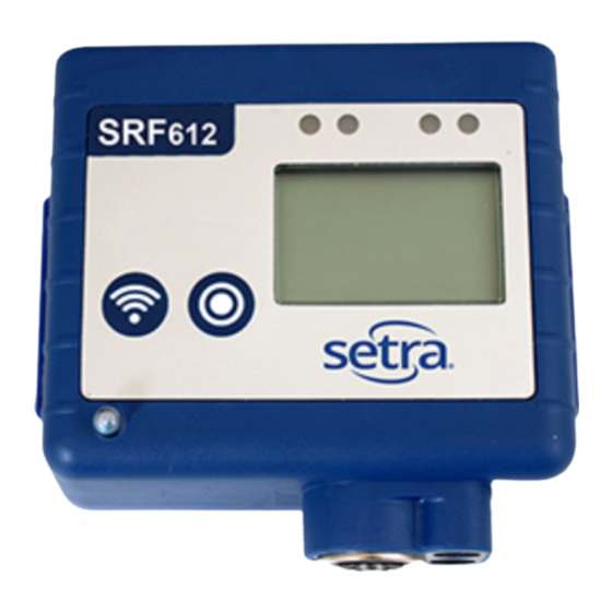
Wifi Button
The Wifi Button has several functions:
1. Press and hold for one second. The Activity (Green) LED will flash
once to acknowledge the button press and you will hear a beep.
The tran smitter will attempt to connect to the SetraEDGE™ and
send any unsent data and/or receive any new tasks. During this
time the lower segment of the WiFi Signal Icon will flash.
2. Press and hold for five seconds. The transmitter will go into
Survey Mode and check the WiFi Signal Strength. To exit press
the WiFi Button again.
3. The LCD will display "SUr" and then switch to display negative
numbers.
Values above -59dB are good to excellent - 4 bars on the LCD
Values in the range -60 to -79 dB are OK - 3 bars on the LCD
Values below -80dB are poor - 2 bars on the LCD
4. Press and hold the WiFi Button and Action Button simultaneously
for five seconds to place the transmitter into Setup Mode. Press
the WiFi Button again to exit Setup Mode.
SRF600 Quick Start Guide
Cable Ties
Use these to tidy and secure
any cables post-installation and
Integral Thermistor Sensor*
prevent cables from pulling out
of their sockets.
(*The internal Channel on SRF614 is inside the Lumberg Plug)
Action Button
The Action Button allows you to navigate between Active Channels.
1. Press once to change the Active Channel that is displayed.
2. Press and hold the Action Button and WiFi Button
simultaneously for five seconds to place the transmitter into
Setup Mode.
Alarm (Red) LED
The Alarm (Red) LED will flash whenever one or more channels is in
an active (unacknowledged) alarm state. It will not flash for High and
Low Warning states, but will flash for High and Low Alarm states.
Activity (Green) LED
Activity (Red) LED
Fault Alert
WiFi Signal
WiFi Button
Action Button
(*Not SRF614)
Action Icons
Door Sensor Alert
Alarm (Green) LED
The Activity (Green) LED will flash briefly every second to indicate that the
transmitter is operating normally. The Activity (Green) LED will also flash
once whenever the WiFi Button has been operated.
Infrared LEDs
The Infrared LEDs are only used during the manufacturing process and
do not display or have any significance in normal operation.
Power and Diagnostic LEDs
These illuminate at various times depending on transmitter interactions.
If both the Red and Yellow LEDs are illuminated, then the Transmitter is
communicating with SetraEDGE.
Infrared LEDs
2-Pin Power Supply Socket
3-Pin Power Sensor Socket
6-Pin Lumberg Probe Socket
1. Green - If the RF520 Mains PSU is plugged in then GREEN LED will
illuminate
2. Yellow - The YELLOW LED indicates that the Transmitter is attempting to
connect to the WiFi
3. Red - When the RED LED illuminates then the Wi-Fi card is active
Scale Selected
Low Battery Indicator
Power and
Diagnostic LEDs
Mounting Plate
Current Active Alert
Alarm Active Alert
High/Low Alarms
Advertisement

Related Manuals for Setra Systems SRF600

Summary of Contents for Setra Systems SRF600
- Page 1 SRF600 Quick Start Guide Activity (Green) LED Infrared LEDs Activity (Red) LED Scale Selected Low Battery Indicator Also Included: Fault Alert Power and WiFi Signal Diagnostic LEDs Mounting Plate WiFi Button Current Active Alert Alarm Active Alert Mounting Bracket Cable Ties...
- Page 2 The transmitter now needs to be configured to connect to the diagnostic LED will show on the side of the transmitter. on whether SRF600 device(s) will connect on the intranet or internet Local WiFi (Wireless) Network and be associated with your active side.
Need help?
Do you have a question about the SRF600 and is the answer not in the manual?
Questions and answers