
Subscribe to Our Youtube Channel
Related Manuals for Bently Nevada 3500/93

Summary of Contents for Bently Nevada 3500/93
- Page 1 Part number 137412-01 Revision E, April 2002 3500/93 SYSTEM DISPLAY OPERATION AND MAINTENANCE MANUAL...
- Page 2 3500/93 SYSTEM DISPLAY © Bently Nevada LLC 2001 Data subject to change without notice All Rights Reserved No part of this publication may be reproduced, transmitted, stored in a retrieval system or translated into any human or computer language, in any form or by any means, electronic, mechanical, magnetic,...
- Page 3 Additional Information Note This manual does not contain all the information required to operate and maintain the Display Interface Module and Display Unit. Refer to the following manuals for other required information. 3500 Monitoring System Rack Installation and Maintenance Manual (129766-01) •...
-
Page 4: Table Of Contents
3.3 Rack Mount 3.4 Panel Mount 3.5 Independent Mount 3.6 Installing External Power Supply 3.6.1 Installing a Bently Nevada External Power Supply 3.6.2 Wiring a User Supplied External Power Supply 4. Configuration Information 4.1 Creating Custom Display Sets 4.2 Defining Display Unit Settings 4.3 Software Switch... - Page 5 7.3 Performing Firmware/LCD Module Upgrades 7.3.1 Display Interface Module Firmware Installation Procedure 7.3.2 Display Unit Firmware/LCD Module Installation Procedure 8. Troubleshooting 8.1 Self-test 8.2 LED Conditions 8.3 System Event List Messages 8.4 Alarm Event List Messages 8.5 Display Unit Busy Flag Checking 9.
- Page 6 3500/93 SYSTEM DISPLAY...
-
Page 7: Receiving And Handling Instructions
1. Receiving and Handling Instructions 1.1 Receiving Inspection Visually inspect the module for obvious shipping damage. If shipping damage is apparent, file a claim with the carrier and submit a copy to Bently Nevada Corporation. 1.2 Handling and Storing Considerations Circuit boards contain devices that are susceptible to damage when exposed to electrostatic charges. -
Page 8: General Information
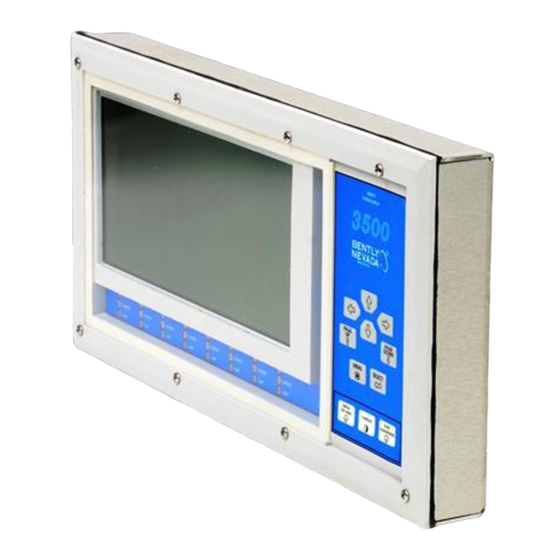
3500/93 SYSTEM DISPLAY General Information The 3500 System Display lets you collect data from all active channels in a 3500 rack and display them on an LCD that can be mounted in a convenient location. A 3500 Monitoring System can have up to two 3500 System Displays. -
Page 9: Display Interface Module And I/O Module
General Information 2.2 Display Interface Module and I/O Module The Display Interface Module and the Display Interface I/O Module are full-height 3500 modules that fit into a 3500 rack and support one Display Unit. The Display Interface Module and the I/O module can be installed in any slot except when a system face mount option is used. -
Page 10: Led Description
3500/93 SYSTEM DISPLAY (or 16 proportional values in text format), two Display Interface Modules can be installed in the same rack to support two Display Units. 2.4 LED Description The LEDs on the front panel of the Display Unit and the Display Interface Module indicate the operating status of the module as shown in the following figures. -
Page 11: Display Interface Module Leds
General Information 2.4.2 Display Interface Module LEDs 1) OK LED Indicates that the Display Interface Module is operating correctly. 2) TX/RX LED Flashes at the rate that messages are received from other 3500 modules. -
Page 12: Installing The Display Unit
Display Unit. In this case the 3500/93 must be installed in slot 15. The 3500/93 System Face Mount option is not compatible with the 3500/05 Mini-rack. -
Page 13: System Face Mount
3.2 System Face Mount 1) Install the Display Unit to the system mount assembly using 10-32x.37 Phillips pan head screws (4 places). The 3500/93 System Face Mount option is not compatible with the 3500/05 A02 Mini-rack. 2) Open the frames of the system mount assembly as shown (2 places). -
Page 14: Rack Mount
3500/93 SYSTEM DISPLAY 3.3 Rack Mount 1) Install the Display Unit to the Rack Mount Adapter using 10-32x.37 Phillips pan head screws (4 places). 2) Install the Rack Mount Adapter to the rail using proper screws and washers (user supplied). -
Page 15: Panel Mount
10-32x1.25 Phillips pan head screws (4 places). The panel mount clamp dimensions are: (WxH) 409.7±1.25 mm (16.13±0.05 in) x 200.15±1.25 mm (7.88±0.05 in) 4) Connect the cables. Mounting Hardware Description Bently Nevada Part Number Quantity 3500 Display Unit Clamp 136977-01 10-32x1.25 Phillips pan head screw... -
Page 16: Independent Mount
Display Unit and the Independent Mount Housing (4 places). Mounting Hardware Description Bently Nevada Part Number Quantity Stainless Steel Independent Mount Housing 137835-01 3500/93 Independent Mount Bracket 137836-01 10-32x0.37 Phillips Pan Head Screw 04344178 10-32x0.75 Phillips Pan Head Screw 04344186 Neoprene Seal Washer 03810112 No. -
Page 17: Installing External Power Supply
Installation of the Display Unit farther than 100 ft. from the rack requires an external power supply to power the Display Unit. This section shows a typical installation of a Bently Nevada external power supply and a user supplied external power supply. -
Page 18: Wiring A User Supplied External Power Supply
3500/93 SYSTEM DISPLAY Mounting Hardware Description Bently Nevada Part Number Quantity Stainless Steel Independent Mount Housing 137835-01 3500/93 Independent Mount Bracket 137836-01 10-32x0.37 Phillips Pan Head Screw 04344178 10-32x0.75 Phillips Pan Head Screw 04344186 Neoprene Seal Washer 03810112 No. 10 Flat Washer 04281412 Conduit Fitting 0.75 NPT... -
Page 19: Configuration Information
Configuration Information Configuration Information The 3500 Display Interface Module supports two types of display units, the 3500 Display Unit or optional third party Modbus displays. For information about configuring the interface module for an optional Modbus® Display, contact Bently Nevada Systems Integration Services through your local sales office. - Page 20 3500/93 SYSTEM DISPLAY To create a custom display set, use the Display Interface Module dialog in the 3500 Configuration Software as follows: 1) Enter a name for the set here. 2) Select a set type - Text or Bargraph. 3) Click on a module.
-
Page 21: Defining Display Unit Settings
Configuration Information The Active Channel list box will display the user defined channel names. The user defined channel names are entered in the monitor channel option screens. If the channel names are not defined, the Active Channel list box will display the coded names with the following meaning: Note The custom display sets that you define may become invalid if monitor channels in the rack... -
Page 22: Software Switch
3500/93 SYSTEM DISPLAY 4.3 Software Switch The only software switch available on the Display Interface Module is the “Configuration Mode” module switch. This switch allows the Display Interface Module to be configured. When a configuration is downloaded from the Rack Configuration Software, the switch will automatically be enabled and disabled by the software. -
Page 23: Module And Channel Statuses
Configuration Information 4.4 Module and Channel Statuses The Display Interface Module returns both module and channel statuses through a verification screen in the 3500 Rack Configuration Software. This section describes the available statuses and where the statuses can be found. Module Status (Display Interface Module Status) Indicates if the Display Interface Module is functioning correctly. -
Page 24: I/O Module Description
3500/93 SYSTEM DISPLAY I/O Module Description The Display Interface I/O Module has an RS422 communication port that is the same as the port on the Display Interface Module. This I/O module lets you connect the communication cable from the Display Unit to the rear of the 3500 rack. -
Page 25: Installing A Display Unit Within 100 Feet Of The I/O Module
RS422 signal lines. The back-lighted Display Unit always requires an external power supply, regardless of distance from the 3500 rack. Display Interface Extension Cable Part Numbers Bently Nevada Cable Part Numbers (Assembled D-Sub Cables): 136634-0010-01 10 ft cable with PVC insulation... -
Page 26: Installing A Display Unit Farther Than 100 Feet From The I/O Module
3500/93 SYSTEM DISPLAY 5.3 Installing a Display Unit farther than 100 feet from the I/O Module Installing the Display Unit farther than 100 feet from the Display Interface I/O Module or installing a back-lighted Display Unit requires an external power supply, adapter, and RS422 extension cable. - Page 27 I/O Module Description Installing the back-lighted Display Unit in the System Mounting configuration (A05) requires an External Power Supply, a back-light Display Interface Module (p.n. 135799-02) and a Power Cable (p.n. 146085-01). The following figures show typical wiring for the external power supply.
-
Page 28: 500 Ft Extension Cable Part Numbers
3500/93 SYSTEM DISPLAY The Display Unit can support input voltage range from +10 Vdc to +18 Vdc. The Display Unit can dissipate 5.6 watt of power, maximum. The back-lighted Display Unit requires +12 Vdc and can dissipate 12 Watts of power maximum. -
Page 29: Operating The Display Unit
Operating the Display Unit Operating the Display Unit This section shows how to use the main menu and the buttons on the keypad to access options and control displays on the Display Unit. Before you can use the Display Unit, you need to •... -
Page 30: Buttons On The Keypad
3500/93 SYSTEM DISPLAY 6.2 Buttons on the Keypad The buttons shown in the following table let you control how data is displayed on the LCD: Display Mode Keypad Button Bargraph, Scan* or Highlight a channel Display the next Display the Channel... - Page 31 Operating the Display Unit The utility function keys let you control the following items: Press this key… to… reset the Display Unit and put the unit into self test. (Upon reset, the Display Unit uploads the rack configuration from the Display Interface Module.) adjust the setting for the contrast of the LCD.
-
Page 32: Ways To Display Data
3500/93 SYSTEM DISPLAY 6.3 Ways to Display Data The 3500 Display Unit lets you display data in 3 formats and lets you scan through data 2 ways - manually using the arrow keys and page keys or automatically using the scan mode. -
Page 33: Scanning Through Data
Operating the Display Unit 6.3.2 Scanning through Data The Display Unit can show data from only a limited number of channels at a time. Scanning lets you display the data from large sets of channels by scrolling through the data manually or automatically. Both methods scroll through data using one of two sequences - the default sequence or a sequence based on custom data sets. -
Page 34: Maintenance
7.3 Performing Firmware/LCD Module Upgrades Occasionally it may be necessary to replace the original firmware that is shipped with the 3500/93 Display Interface Module (DIM). The following instructions describe how to replace the existing DIM firmware, the existing Display Unit (DU) firmware and the DU LCD module. -
Page 35: Display Interface Module Firmware Installation Procedure
Maintenance 7.3.1 Display Interface Module Firmware Installation Procedure The following steps will need to be followed to complete the Display Interface Module firmware upgrade: Ensure that the Module’s configuration is saved using the 3500 Rack Configuration software. Refer to Section 1.2 (Handling and Storing Considerations) before handling the monitor or the upgrade firmware IC. - Page 36 3500/93 SYSTEM DISPLAY Step 2. Move the top shield up and down to work it loose from the two front standoffs. 7.3.1.2 Original Firmware IC Removal Step 1. Insert the small flathead screwdriver under the lip of either end of the firmware IC.
-
Page 37: Display Unit Firmware/Lcd Module Installation Procedure
Maintenance 7.3.1.3 Upgrade Firmware IC Installation 7.3.1.4 Install the upgrade firmware IC into the PWA. Step 1. Install the new firmware chip into the socket on the PWA. Be sure that the notched end of the IC is matched to the notched end of the socket. Ensure that the IC is firmly seated in the socket. - Page 38 3500/93 SYSTEM DISPLAY Remove the case from the DU PWA. Remove the original EPROMs and/or LCD module from the DU PWA. Install the upgrade EPROMs and/or LCD module into the DU PWA. Replace the DU case. Replace the DU back into its mounting.
- Page 39 Maintenance Step 2. Remove the four 10-32 Phillips head screws from the DU backplate and withdraw the DU from the mounting. 7.3.2.2 Remove the case from the DU PWA. Step 1. Place the DU front side up on a flat, static safe surface and remove the eight 6-32 X 1-1/4 Phillips head screws from the front of the DU.
- Page 40 3500/93 SYSTEM DISPLAY Step 2. If you are replacing the LCD module only, and not upgrading the firmware then skip section 7.3.2.3 and 7.3.2.4 and proceed to section 7.3.2.5. Carefully lift up the right (keypad side) of the display approximately 4 inches.
- Page 41 Maintenance 7.3.2.4 Install the upgrade EPROMs into the sockets on the DU PWA. Step 1. Install the U13 upgrade. For Display Unit versions 001.xxx, Place part number 137353-01 into the U13 socket on the PWA. For Display Unit versions 002.xxx, Place part number 145703-01 into the U13 socket on the PWA. Be sure that the notched end of the IC is matched to the notched end of the socket.
- Page 42 3500/93 SYSTEM DISPLAY 7.3.2.5 Display Unit LCD Module Replacement Step1. Remove the LCD module. Use a nutdriver to remove the four 6-32 x ¼ hex nuts from the LCD mounting studs. Carefully lift up the LCD module, about an inch or two, so that you can see the flex connector pigtail. Note how the pigtail(s) is/are routed.
- Page 43 Maintenance 7.3.2.7 Replace the DU back into its mounting. Step 1. Replace the Display Unit back into its mounting by installing the four 10- 32 Phillips head screws. Install the Display Unit pigtail back into its original socket. 7.3.2.8 Run Test Mode and verify correct keypad operation. Step 1.
-
Page 44: Troubleshooting
3500/93 SYSTEM DISPLAY Troubleshooting This section describes how to troubleshoot a problem with the Display Interface Module or the Display Unit by using the information provided by the self-test, the LEDs, System Event List, and the Alarm Event List. 8.1 Self-test To perform the Display Interface Module self-test: 1. -
Page 45: Led Conditions
Troubleshooting 8.2 LED Conditions The following table shows how to use the LEDs to diagnose and correct problems. Display Interface Module: TX/RX Scenario Action 1 Hz 1 Hz Display Interface Module is Reconfigure the module or exit not configured or in Configuration. - Page 46 3500/93 SYSTEM DISPLAY New Alarm Overall Rack Status LEDs Event LED Danger Alert Conditions New alarm event has been detected since the last alarm event acknowledgment. The LED can be turned off by pressing the “Alarm Event Acknowledgment” button. OFF* No new alarm event.
-
Page 47: System Event List Messages
Troubleshooting Channel Status LEDs (8 Sets) Danger Alert Conditions Channel(s) above the LED is OK. OFF* Channel(s) above the LED is Not OK. The channel(s) above the LED is in Danger alarm status. OFF* The channel(s) above the LED is not in Danger alarm status. - Page 48 3500/93 SYSTEM DISPLAY Class Value Classification Severe/Fatal Event Potential Problem Event Typical logged Event Reserved Event Date: The date the event occurred. Event Time: The time the event occurred. Event Specific: Provides additional information for the events that use this field.
- Page 49 Troubleshooting Device Not Communicating Event Number: 32 Event Classification: Potential Problem Action: Check to see if one of the following components is faulty: • the Display Interface Module • the rack backplane Device Is Communicating Event Number: 33 Event Classification: Potential Problem Action: Check to see if one of the following components is faulty: •...
- Page 50 3500/93 SYSTEM DISPLAY Pass Main Board +5V-A (Pass Main Board +5V - upper Power Supply) Event Number: 101 Event Classification: Potential Problem Action: Verify that noise from the power source is not causing the problem. If the problem is not caused by noise, check to see if one of the following components is faulty: •...
- Page 51 Troubleshooting Fail Main Board +17V-A (Fail Main Board +17V - upper Power Supply) Event Number: 152 Event Classification: Potential Problem Action: Verify that noise from the power source is not causing the problem. If the problem is not caused by noise, check to see if one of the following components is faulty: •...
- Page 52 3500/93 SYSTEM DISPLAY Pass Main Board +12V (Pass Main Board +12V - Second stage regulator) Event Number: 157 Event Classification: Severe/Fatal Event Action: Verify that noise from the power source is not causing the problem. If the problem is not caused by noise, check to see if the following component is faulty: •...
- Page 53 Troubleshooting Module Removed from Rack Event Number: 325 Event Classification: Typical Logged Event Action: No action required. Module Inserted in Rack Event Number: 326 Event Classification: Typical Logged Event Action: No action required. Device Events Lost Event Number: 355 Event Classification: Typical Logged Event Action: No action required.
-
Page 54: Alarm Event List Messages
3500/93 SYSTEM DISPLAY 8.4 Alarm Event List Messages The following Alarm Event List Messages are returned by the Display Interface Module and the Display Unit. Alarm Event List Message When the message will occur Entered Not OK module went Not OK... -
Page 55: Ordering Information
The 3500 System Display requires 2.30 or later version of the Rack Configuration Software. Spares / Accessories 3500/93 Display Unit 135785-01 3500/93 Back-lighted Display Unit 135785-02 3500/93 Display Interface Module 135799-01 3500/93 Display Interface Module (A05 thru A08 options) 135799-02 3500/93 Display Interface I/O Module 135813-01... - Page 56 3500/93 SYSTEM DISPLAY 3500/93 System Display Operation & Maintenance Manual 137412-01 10 Foot Cable (PVC) 136634-0010-01 50 Foot Cable (PVC) 136634-0050-01 50 Foot Cable (Teflon®) 136634-0050-02 100 Foot Cable (PVC) 136634-0100-01 100 Foot Cable (Teflon®) 136634-0100-02 500 Foot Extension Cable (PVC) 130121-02-01 500 Foot Extension Cable (Teflon®)
-
Page 57: Specifications
640x200 Dots LCD Displays data in graphical and text format Communication between Hardware: RS422 Interface the Display Unit and the Protocol: Supports Bently Nevada proprietary Display Interface Module protocol and Modbus protocol based on AEG PI-MBUS-300 Rev. E Reference Manual... - Page 58 3500/93 SYSTEM DISPLAY ENVIRONMENTAL LIMITS Display Interface Module & I/O Module Temperature: -30° C to 65° C (-22° F to 149° F) operating -40° C to 85° C (-40° F to 185° F) storage Humidity: 95% noncondensing Display Unit Temperature: -20°...
- Page 59 Specifications PHYSICAL Display Interface Module: Dimensions (Height x Width x 241.3 mm x 24.4 mm x 241.8 mm Depth) (9.50 in x 0.96 in x 9.52 in) Weight: 0.82 kg (1.82 lb) Display Interface I/O Module: Dimensions (Height x Width x 241.3 mm x 24.4 mm x 99.1 mm Depth) (9.50 in x 0.96 in x 3.90 in)
Need help?
Do you have a question about the 3500/93 and is the answer not in the manual?
Questions and answers