
Subscribe to Our Youtube Channel
Related Manuals for Bently Nevada 3300/46

Summary of Contents for Bently Nevada 3300/46
- Page 1 (217) 352-9330 | Click HERE Find the GE / Bently Nevada 3300/46-07-04-00-00 at our website:...
- Page 2 1)014-f = j I 17 • PART NO. 84413-01 3300/46 RAMP DIFFERENTIAL EXPANSION MONITOR • OPERATION MANUAL BENTLY • • • • • • • NEVADA .yi " .a.m.ci c i l s .
- Page 3 NOTICE READ THE FOLLOWING BEFORE INSTALLING OR OPERATING EQUIPMENT Bently Nevada Corporation has attempted to identify areas of risk created by improper installation and/or operation of this product. These areas of information are noted as WARNING or CAUTION for your protection and for the safe and effective operation of this equipment. Read all instructions before installing or operating this product.
- Page 4 • 84414-01 Ramp Differential Expansion Monitor Maintenance 1 12 1 Te s t OK Limits A \ CAUTION Test will exceed alarm setpoint levels causing alarms to activate. This could result in relay contact to change state. See Danger Bypass section 10. A \ WARNING High Voltage present.
- Page 5 ,wwwwim. 8 4 4 1 4 - 0 1 Ramp Differential Expansion Monitor Maintenance 1.11.111\ 12 T e s t OK Limits Cont. • 6. Verify that the OK relay changes state (de- energized). Note : all other channels in the ' l i l t ) , 4 6 rack must be OK or bypassed in order for the 011-FE:ENT I At_...
- Page 6 Ramp Differential Expansion Monitor Maintenance 84414-01 L I id Calibrate Channels C A U T I O N Figure 1 [0.q1113, tways, J r L E i c . . . 1 0 1 Monitoring will be bypassed CINIGUM I 101 automatically during calibration.
- Page 7 84414-01 • Ramp Differential Expansion Monitor Maintenance Calibrate Channels FCont. 1. Disconnect COM and IN wiring from the Channel A terminals on the Signal Input Relay Module. 2. Connect a power supply and a multimeter to COM and IN with polarity as shown in Figure 1 on page 24.
- Page 8 • Ramp Differential Expansion Monitor Maintenance 84414-01 1 13 I C a l i b r a t e Channels [Conti 8. Activate the Channel A gain adjust dip switch (GA) by moving it to the left. The Channel A bargraph will begin t o flash. Measure the voltage at Test point Channel A (TA) using the multimeter.
- Page 9 • 84414-01 Ramp Differential Expansion Monitor Maintenance 1 13 I C a l i b r a t e Channels [Cont] 12. A c t i v a t e the meter adjust dip switch (MA) by moving i t t o t h e left. T h e differential expansion signal will begin to flash on the left LCD display.
- Page 10 Keyphasor® is a registered trademark of Bently Nevada Corporation • Proximitor i s a registered trademark of Bently Nevada Corporation Document No. 84413 . First Printing: May 1989 . Revision NC: May 1989 Copyright() 1 9 8 9 Bently Nevada Corporation...
- Page 11 • Ramp Differential Expansion Monitor Operation Blank Page...
-
Page 12: Table Of Contents
• 84413-01 Ramp Differential Expansion Monitor Operation CONTENTS SECTION TITLE Differential Expansion Monitor System Monitor Options 3. P r o g r a m m a b l e Options 4. M o n i t o r Functions 6. B y p a s s 7. - Page 13 • Ramp Differential Expansion Monitor Operation • Blank Page •...
-
Page 14: Differential Expansion Monitor System
• 84413-01 Ramp Differential Expansion Monitor Operation 1 DIFFERENTIAL EXPANSION MONITOR SYSTEM SIGNAL INPUT RELAY MODULE LOCATION 3300/48 DIFFERENTIAL EXPANSION MONITOR 3300 RACK < 1 : = 1 s — ' 2 1-1 PROXIMITOR ` 4 ( 6 7 4 € L ^ CHANNEL B PROBE <... -
Page 15: Monitor Options
MONITOR PART NUMBER TRANSDUCER AGENCY FULL SCALE RANGE I N P U T A L A R M RELAY APPROVAL 3300/46 01 = 5-0-5mm 01 = 11mm, 00 = NONE 00 = NOT REQUIRED 02 = 0 - 10mm 100 mV/mil 01 = EPDXY 01 = CSA 03 = 0.25-0-0.25 INCHES... - Page 16 • 84413-01 Ramp Differential Expansion Monitor Operation I 3 I PROGRAMMABLE OPTIONS MONITOR FEATURE OPTION MONITOR FEATURE OPTION FIRST OUT DANGER MODE LATCHING * ENABLED * DISABLED NONLATCHING RECORDER OUTPUTS ALARM DELAYS 0.1 SECOND +4 TO +20 mA * 1 SECOND +1 TO +5 Vdc 3 SECOND * 0 TO -10 Vdc...
-
Page 17: Monitor Functions
Ramp Differential Expansion Monitor Operation 84413-01 MONITOR FUNCTIONS RAMP DIFFERENTIAL EXPANSION - The Ramp Differential Expansion Monitor provides continuous monitoring of shaft growth relative to the machine case. Normal expansion direction can be toward or away from the probe A. PROBE GAP VOLTAGE - Probe gap is measured as a negative dc voltage that is directly proportional to the gap distance between the face of a proximity probe and the surface being monitored. - Page 18 • 84413-01 Ramp Differential Expansion Monitor Operation MONITOR FUNCTIONS RECORDER OUTPUT - Depending on the option selected, the recorder output levels proportional to the measured differential expansion signal are 0 to -10Vdc, +1 to +5Vdc, or +4 to +20mA. SELF TEST - The monitor has three categories of self test: Power-up, Cyclic, and User-invoked. Power-up self test is performed automatically each time the monitor power is turned on.
- Page 19 • Ramp Differential Expansion Monitor Operation 84413-01 NOTE: EACH CHANNEL IN THE SYSTEM CONTROLS THE OK RELAY. THEREFORE, EITHER CHANNEL CAN CAUSE A NOT OK RELAY CONDITION (DEENERGIZED RELAY) LED DISPLAY • RELAY DRIVE * CONDITION • • CHANNEL A AND B IN OPERATING RANGE •...
-
Page 20: Bypass
• 84413-01 Ramp Differential Expansion Monitor Operation BYPASS LED DISPLAY CONDITION • LONG S H O R T MONITOR IN DANGER BYPASS MODE • • BYPASS SYSTEM IN POWER-UP MODE USER-INVOKED SELF TEST IN PROGRESS MONITOR BYPASSED CALIBRATION MODE BYPASS MONITOR OVERRANGE DURING CALIBRATION •... -
Page 21: Alert
Ramp Differential Expansion Monitor Operation ALERT LED DISPLAY ALERT CONDITION RELAY DRIVE LONG • ALERT DIFFERENTIAL EXPANSION SIGNAL HAS EXCEEDED THE LONG ALERT LEVEL (SEE SECTION 11) DIFFERENTIAL EXPANSION SIGNAL ALERT • HAS EXCEEDED THE SHORT ALERT • LEVEL (SEE SECTION 11) ALERT FIRST OUT CONDITION FOR DIFFERENTIAL EXPANSION SIGNAL... -
Page 22: Danger
• 84413-01 Ramp Differential Expansion Monitor Operation DANGER • LED DISPLAY DANGER RELAY DRIVE CONDITION LONG • DANGER DIFFERENTIAL EXPANSION SIGNAL HAS EXCEEDED THE LONG DANGER LEVEL (SEE SECTION 11) DIFFERENTIAL EXPANSION SIGNAL DANGER • HAS EXCEEDED THE SHORT DANGER LEVEL (SEE SECTION 11) DANGER FIRST OUT CONDITION FOR... -
Page 23: Read Channel Differential Expansion
84413-01 Ramp Differential Expansion Monitor Operation READ CHANNEL DIFFERENTIAL EXPANSION THE MONITOR CONTINUOUSLY INDICATES THE DIFFERENTIAL EXPANSION SIGNAL MEASURED FROM ZERO POSITION TO THE DIFFERENTIAL EXPANSION SIGNAL VALUE ON THE LEFT METER SCALE. THE DIFFERENTIAL EXPANSION SIGNAL IS A COMPOSITE SIGNAL GENERATED FROM BOTH CHANNEL A AND CHANNEL B PROBE INFORMATION. -
Page 24: Read Gap Voltage
• 84413-01 Ramp Differential Expansion Monitor Operation READ GAP VOLTAGE PRESS GAP SWITCH AND READ GAP VOLTAGE FOR BOTH CHANNEL A AND CHANNEL B ON THE METER USING THE CENTER METER SCALE. • CHANNEL A PROBE SHAFT •... -
Page 25: Read Setpoint Levels
Ramp Differential Expansion Monitor Operation 84413-01 READ SETPOINT LEVELS PRESS ALERT SWITCH AND READ ALERT PRESS DANGER SWITCH AND READ DANGER SETPOINTS ON THE METER SCALE. BOTH SETPOINTS ON THE METER SCALE. BOTH LONG AND SHORT ROTOR SETPOINTS ARE LONG AND SHORT ROTOR SETPOINTS DISPLAYED. - Page 26 • 84413-01 Ramp Differential Expansion Monitor Operation I 1 2 1 SELF TEST THE MONITOR HAS THREE LEVELS OF SELF TESTS: POWER-UP TEST: PERFORMED ONLY WHEN MONITOR IS TURNED ON. CYCLIC TEST: PERFORMED CONTINUOUSLY. USER-INVOKED TEST: PERFORMED ONLY WHEN INITIATED BY USER. IF ERRORS ARE DETECTED DURING CYCLIC SELF TESTS: 1 .
-
Page 27: S E L F Test
• Ramp Differential Expansion Monitor Operation 84413-01 SELF TEST [CONT] INITIATE USER-INVOKED TEST BY SHORTING ACROSS TWO SELF TEST (ST) PINS. CAUTION Machine Protection Will Be Lost For Duration of Test AT COMPLETION OF USER-INVOKED SELF TEST, MONITOR WILL RECALL STORED ERROR CODES, IF ANY. THESE •... - Page 28 • Ramp Differential Expansion Monitor Operation 84413-01 SELF TEST [CONT] DESCRIPTION ERROR CODE ROM CHECKSUM HAS FAILED. * 3 3 o o / . 6 DIFFERENTIAL EEPROM FAILURE NO. 1. * * EXP ANSI O N MONITOR M E M M I I I M M M E W E E P R O M FAILURE NO.
-
Page 29: Index
Ramp Differential Expansion Monitor Operation 84413-01 INDEX Page ALARM ALARM DELAYS ALARM RELAYS ALERT 8, 12 ALERT MODE BUFFERED OUTPUT BYPASS CYCLIC TEST DANGER 9, 12 DANGER BYPASS DANGER MODE ERROR CODES FIRST OUT GAP VOLTAGE METER RESPONSE TIME NOT OK MODE NOT OK MONITOR DEFEAT 4, 6 OK RELAY... - Page 30 • PART NO. 84414-01 3300/46 RAMP DIFFERENTIAL EXPANSION MONITOR MAINTENANCE MANUAL BENTLY r. NEVADA •...
- Page 31 Notice READ THE FOLLOWING BEFORE INSTALLING OR OPERATING EQUIPMENT Bently Nevada Corporation has attempted to identify areas of risk created by improper installation and/or operation of this product. These areas of information are noted as WARNING or CAUTION for your protection and for the safe and effective operation of this equipment. Read all instructions before installing or operating this product.
- Page 32 3300/01 System Monitor, 80175 3300/46 Ramp Differential Expansion Operation, 84413-01 • Keyphasor® is a registered trademark of Bently Nevada Corporation ProximitorS is a registered trademark of Bently Nevada Corporation Document No. 84414 • First Printing: May 1989 • Revision A: December 1989 Copyright©...
- Page 33 84414-01 • Ramp Differential Expansion Monitor Maintenance • Blank Page...
- Page 34 84414-01 • Ramp Differential Expansion Monitor Maintenance Contents SECTION 1. D i f f e r e n t i a l Expansion Monitor System 2. F r o n t Panel Features 3. M o n i t o r Removal 4.
- Page 35 84414-01 Ramp Differential Expansion Monitor Maintenance Blank Page...
-
Page 36: Differential Expansion Monitor System
84414-01 R a m p Differential Expansion Monitor Maintenance Differential Expansion Monitor System S I G N A L I N P U T R E L AY MODULE L O C AT I O N c'T.X 3 3 0 0 / 4 6 DIFFERENTIAL EXP ANSION MONITOR m a i n I P E O... -
Page 37: Front Panel Features
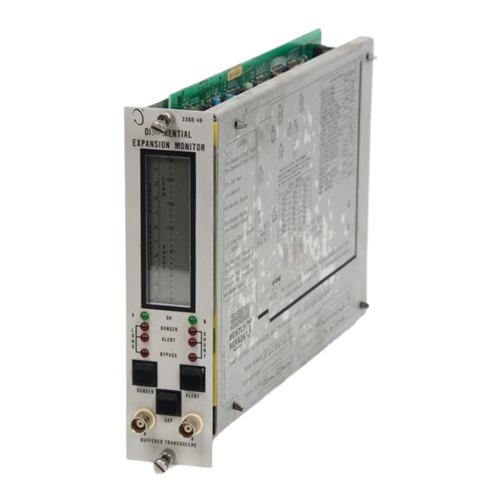
84414-01 • Ramp Differential Expansion Monitor Maintenance Front Panel Features 3 3 0 0 / 4 6 DIFFERENTIAL EXPANSION MONITOR = L-20- Bargraph - Indicates Differential Expansion value Transducer OK LED Danger Alarm LED Alert Alarm LED DAN ; E P Bypass LED RYPAS=, Read Monitor Danger Setpoints... -
Page 38: Monitor Removal
84414-01 • Ramp Differential Expansion Monitor Maintenance Monitor Removal CAUTION The machine i s n o t protected when the monitor is removed from the rack. 1. Loosen two screws. 2. Pull monitor from rack. •... -
Page 39: Monitor Disassembly
84414-01 • Ramp Differential Expansion Monitor Maintenance Monitor Disassembly MAIN C I R C U I T BOARD STANDOFF ( 4 P L A C E S Side Cover Removal Squeeze t h e retaining t i p s o n e a c h standoff, a n d r e m o v e t h e s i d e c o v e r from the monitor. - Page 40 84414-01 • R a m p Differential Expansion Monitor Maintenance Monitor Disassembly [Cont] Front Panel Removal \VASHEC RETA N N C SPR N C c,CRE'Ai S L I D r' //STANDOFF • •...
- Page 41 84414-01 • Ramp Differential Expansion Monitor Maintenance Signal Input Relay Module (Dual Relay) WARNING High Voltage present Could cause shock, burns or death. Do Not touch exposed wires or terminals. The Signal Input Relay Module is on the back o f t h e r a c k .
-
Page 42: S I G N A L Input Relay Module
84414-01 111 0 Ramp Differential Expansion Monitor Maintenance 5 I Signal Input Relay Module (Quad Relay) WARNING High Voltage present Could cause shock, burns • or death. 1 ! I 444. Do Not touch exposed wires or terminals. I C : 2 1 The Signal Input Relay Module is on the It31 back o f t h e r a c k . - Page 43 MONITOR PART NUMBER TRANSDUCER FULL SCALE RANGE I N P U T A L A R M RELAY A P P R O V A L 3300/46 00 = NOT REQUIRED 01 = 5-0-5mm 01 = 11mm, 00 = NONE...
- Page 44 84414-01 • Ramp Differential Expansion Monitor Maintenance Monitor Options [Cont] The Ramp Differential Expansion Monitor has several user-programmable options. The options can be changed by removing and installing jumpers on the printed circuit boards. • 1 1 1 1 1 m c c x u u •...
-
Page 45: Monitor Options
Ramp Differential Expansion Monitor Maintenance 84414-01 i l l Monitor Options [Conti Main Board Option Settings All monitor option jumpers for the Ramp DE Monitor are on the Main Board. Table 1 shows these options and their jumper positions. Table 1 Option Settings on Main Board Jumper Option I n s t a l l... - Page 46 Ramp Differential Expansion Monitor Maintenance 84414-01 • Monitor Options [Cont] Table 1 [continued] Jumper Install R e m o v e Option Setting Toward Probe A * W 1 2 C ' Upscale Direction W12C Away from Probe A * Options shipped from factory Recorder Output Options To set the recorder output, remove all jumpers from headers W1A-E, W2A-E, W3A-D, W5A-C, W6A- C, W8A-D, W9A-D, W14G AND W14H.
- Page 47 Ramp Differential Expansion Monitor Maintenance 84414-01 • Monitor Options [Cont] Transducer Type Options To set the monitor for the correct transducer type, remove all jumpers from headers W21C and D, W22B-D, W4A-F, and W16 and W17. Install jumpers specified in Table 3. Table 3.
- Page 48 84414-01 • Ramp Differential Expansion Monitor Maintenance Monitor Options [Cont] Ramp Angle Options The following table, Table 5, shows the acceptable ramp angle ranges for different meter range and transducer type combinations. I f possible, however, avoid using ramp angle combinations specified in Table 6 since accuracy is reduced.
- Page 49 Ramp Differential Expansion Monitor Maintenance 84414-01 Monitor Options [Cont] • Ramp Angle Options (cont.) To set the monitor for the correct ramp angle, remove jumpers W20A-F. Install jumpers specified in Table 7. Table 7. Ramp Angle Options Ramp Angle Install Jumpers Ramp Angle Install Jumpers W200...
-
Page 50: Meter Scale Replacement
84414-01 Ramp Differential Expansion Monitor Maintenance Meter Scale Replacement The Monitor meter scales can be replaced for operation with different full scale ranges. The replacement meter scales are located in the back of this manual. To replace a meter scale : 1. -
Page 51: Alarm Setpoint Adjust
Ramp Differential Expansion Monitor Maintenance 84414-01 Alarm Setpoint Adjust 1. Open front panel. DIFFERENTIAL EXPANSION IGNITOR 2. Set switch the Setpoint Adjust switch (SA) to the left (ON). 3. Select Short rotor setpoints by setting the Long/Short (US) switch to the right. The left bargraph will start flashing the differential expansion signal. -
Page 52: Monitor Bypass
84414-01 4110 R a m p Differential Expansion Monitor Maintenance Monitor Bypass Set MB (Monitor Bypass) switch to the left (ON). The BYPASS LEDs come on, the OK LEDs go off, and the Differential Expansion signal is clamped to Zero Position. CAUTION Machine Protection will be l o s t while Monitor... - Page 53 Ramp Differential Expansion Monitor Maintenance 84414-01 110 I Danger Bypass • Set DB (Danger Bypass) switch to the left (ON). Both BYPASS LEDs come on. The DANGER alarm LEDs on the front panel can come on but the Danger relay drive will not be activated if a Danger setpoint is exceeded.
- Page 54 84414-01 R a m p Differential Expansion Monitor Maintenance 111 I Te s t Alarms CAUTION ■-1111.111.1= Tests will exceed alarm setpoint P0WOMITOR levels causing alarms t o activate. This could result in relay contact to PROX I O S I TOR change state.
-
Page 55: T E S T Alarms
84414-01 Ramp Differential Expansion Monitor Maintenance Test Alarms [Cont] • DIFFERENTIAL EXPANSION MONITOR 5. Adjust the power supply voltages such that the differential expansion signal o n the monitor just exceeds the Long Alert setpoint level and verify that the Long ALERT LED goes on after the specified delay period has elapsed (Flashing if the first out option is selected). - Page 56 84414-01 R a m p Differential Expansion Monitor Maintenance I 1 1 I Te s t Alarms [Cont] 3300,4. DIFFERENT I AL EXP ANSION MONITOR 10. Press RESET switch on the System Monitor. Verify that Long ALERT and DANGER LEDs remain on and steady.
- Page 57 84414-01 Ramp Differential Expansion Monitor Maintenance 11 2 I Test OK Limits CAUTION .m..Tests will exceed alarm setpoint O R O i o gi T OR levels causing alarms t o activate. This could result in relay contact to change state.
-
Page 58: T E S T Ok Limits
84414-01 Ramp Differential Expansion Monitor Maintenance Test OK Limits [Cont] 6. Verify that the OK relay changes state (deenergized). Note: all other channels in the rack must be OK or bypassed in 3 3 0 0 / 4 6 D I FFERENT I AL order for the relay to change state. -
Page 59: C A L I B R A T E Channels
Ramp Differential Expansion Monitor Maintenance 84414-01 • L i C a l i b r a t e Channels Figure 1 L a e ExPEEES/04 CAUTION I T R I S I B E A R INC LOTO E W E N . , 6 . —.I Monitoring w i l l b e b y p a s s e d CONF M U R AT tOta... - Page 60 84414-01 R a m p Differential Expansion Monitor Maintenance Calibrate Channels [Cont] 1. Disconnect COM and IN wiring from the channel A terminals on the Signal Input Relay Module. 2. Connect a power supply and a multimeter to COM and IN with polarity as shown in Figure 1 on page 24.
- Page 61 84414-01 i l l Ramp Differential Expansion Monitor Maintenance Calibrate Channels [Cont] 8. Activate t h e channel A gain adjust dip switch (GA) b y moving i t t o t h e left. T h e channel A bargraph w i l l b e g i n t o flash. Measure the voltage at Test point channel A (TA) using the multimeter.
- Page 62 R a m p Differential Expansion Monitor Maintenance 84414-01 jCalibrate Channels [Cont] 12. Activate the meter adjust dip switch (MA) by moving it to the left. The differential expansion signal will begin to flash on the left LCD display. 13. Measure the voltage at test point channel A (TA) using the multimeter.
- Page 63 84414-01 Ramp Differential Expansion Monitor Maintenance Calibrate Channels [Cont] • Example: A user has a 25mm probe and a 0.25-0-0.25 inch full scale range. T h e monitor is configured for upscale toward probe A with dual ramp angles of 14 degrees. (1 inch = 1000 mils, 1 V = 1000 mV) TSF = 20mv/mil MR = 0.5 inches...
-
Page 64: Self Test
84414-01 R a m p Differential Expansion Monitor Maintenance Self Test THE MONITOR HAS THREE LEVELS OF SELF TESTS: POWER-UP TEST: PERFORMED ONLY WHEN MONITOR IS TURNED ON. CYCLIC TEST: PERFORMED CONTINUOUSLY. USER-INVOKED TEST: PERFORMED ONLY WHEN INITIATED BY USER. IF ERRORS ARE DETECTED DURING CYCLIC SELF TESTS: MONITORING IS ABORTED UNTIL THE ERROR IS -2 4... - Page 65 84414-01 • Ramp Differential Expansion Monitor Maintenance 14 I Self Test [Cont] INITIATE USER-INVOKED TEST BY SHORTING ACROSS TWO SELF TEST (ST) PINS. CAUTION Machine ProtectionWill B e Lost For Duration of Test AT COMPLETION OF USER-INVOKED SELF TEST, THE MONITOR WILL RECALL STORED ERROR CODES, IF ANY. •...
- Page 66 84414-01 Ramp Differential Expansion Monitor Maintenance Self Test [Cont] ERROR CODE DESCRIPTION ROM CHECKSUM HAS FAILED. * 1 0 e 3 0 0 / 4 6 EEPROM FAILURE NO. 1. * * D I F F E R E N T I A L E X P A N S I O N M O N I T O R EEPROM FAILURE NO.
-
Page 67: F I E L D Wiring Diagrams
Ramp Differential Expansion Monitor Maintenance 84414-01 • 15 F i e l d Wiring Diagram 3300/46 FIELD WIRING f i r _ = 1 , CHANNEL A PROBE C , . IP1 1 Loll /1\3\ C o m a . 3 1 1 CHANNEL. - Page 68 • Ramp Differential Expansion Monitor Maintenance 84414-01 Field Wiring Diagram [Cont] 4. T o minimize ground loop noise problems, a single point earth ground (GND) to system common (COM) connection is recommended. Proximitor case must be electrically isolated from earth ground. Electrical isolation: 500 Vac (RMS) minimum.
-
Page 69: Recommended Spare Parts
84414-01 • Ramp Differential Expansion Monitor Maintenance Recommended Spare Parts Q t y D e s c r i p t i o n P a r t N u m b e r D i f f e r e n t i a l E x p a n s i o n M o n i t o r 3 3 0 0 / 4 6 -1 1 1- 11... -
Page 70: Specifications
• 84414-01 Ramp Differential Expansion Monitor Maintenance Specifications INPUTS Signal Inputs: Two channels proximity input, 10 kohm input impedance. Signal Scale Factors: 100mV/mil (4.0V/mm) - 11 and 14 mm proximity probes. 20mV/mil (0.8V/mm) - 25 and 35 mm proximity probes. 10mV/mil (0.4V/mm) - 50 mm proximity probe. - Page 71 Ramp Differential Expansion Monitor Maintenance 84414-01 Specifications [Cont] RELAY CONTACT RATINGS Dual Relays: 5 A @ 120 Vac 50/60 Hz. 5 A @ 28 Vdc. Quad Relays: 0.6 A @ 120 Vac 50/60 Hz. 2 A @ 30 Vdc. ENVIRONMENTAL Temperature: Operating +32°F to +149°F (0°C to +65°C).
- Page 72 84414-01 R a m p Differential Expansion Monitor Maintenance Page Adjust Alarm Setpoints Alarm Delay Alert ALERT LED Alert Mode Alert Relay Alert Setpoints Bargraph Buffered Transducer Output BYPASS LED Calibrate Channels Calibration Terminology Circuit Board Removal Danger DANGER LED Danger Bypass Danger Mode Danger Relay...
-
Page 73: Index
Ramp Differential Expansion Monitor Maintenance 84414-01 Index • Ramp Option Recorder Output Options Relay Module Relay Module Options Relay Module Removal Side Cover Removal Signal Input Relay Module Spare Parts Specifications Test Alarms Test OK Limits Transducer Type Options Upscale Direction User-programmable options Wiring Recommendations Zero Position Adjustment... -
Page 74: Schematics And Pwa Drawings
• Ramp Differential Expansion Monitor Maintenance 84414-01 Appendix SCHEMATICS AND PWA DRAWINGS • • Appendix... - Page 75 . 0 , 1 A / D I N P U T C I R C U I T • 5 1 / R 2 7 R5.3 N A N M I E N . 1 0 0 5 6 2 0 0 2 I / 2 1 4 1 0 0 K...
- Page 76 • • • .51J 11 6 P P 7 10014 u l g 1 . 11 ' P .>, R . 1 0 1 0 0 4 S 1 0 0 , 1 KIVREF • 5 , 0 ' 1 6 •...
- Page 77 C 5 R ' • • • ' 4 4 5 - P o . • r t 41 3 I 1 D I S C 0 , 5 o t C 1 5 1 , - - C O A 8 1 P A S : _ _ 1 C.H 1 f i .
- Page 78 • E L . / L Y P ! ) . . r.o25 O D DJ 1 1 , 1 P - R A H P ..L E L D 5 1 E H . L H P ot: •...
- Page 79 4 9 9 . 7 7 1 . 7 0 9 0 9 3 1 . 9 0 E12 4 G 1 0 0 P U 3 / 1 2 0 2 0 0 „ K + U 1CO3. 8-"' 9 9 5 0000 I 2 .
- Page 80 • W2)19° ,E,;" 1 Ramp Differential Expansion Monitor Schematic Sheet (6 o f 11)
- Page 81 • 91-1. V e 3 . NO01 i c d e n D 1 0 0 ' • • 0 2 0 . 4 3 2 1 - 0 , 7 - P E 3 4 11 0 L ' r - 1 2 , 1 S r i 1 0 3 3 1 1...
- Page 82 • 9 9 9 .L9 9 9 9 Ramp Differential Expansion Monitor Schematic Sheet (8 of 11)
- Page 83 Fl H. NT I AL Y.PAN':;11..41 11111\11 TRANSDUCER OPT ION ALARM RELAY O FULL S C A L E O P T I O N OPTION DESCRIPTION JUMPERS DESCR OPTION OPTIC"' DESCRIPTION CODE CODE CITPE 6 1 b , W 1 7 , 6 2 1 0 11 m n , 10014V/m1I NONE 5 - 0 - 5 mA...
- Page 84 l i l t I 1 I • C I i • _ 1 _ • Ramp Differential Expansion Monitor Schematic Block Diagram, Sheet (10 of 11)
- Page 85 • ,„ 10.000.0.000.0.00.0.0.0.0.0000000 0.12101-1-0 , 6 £ I d 0 = - 0 s o c a 8 1 i!,;,,_,,,,,, ul 7::411 IFT. - 0 0 - 7 ) L9_i 0 0 1 4 8 E s t I d e l 2 •...
Need help?
Do you have a question about the 3300/46 and is the answer not in the manual?
Questions and answers