
Related Manuals for Ijinus LNU06V3


Summary of Contents for Ijinus LNU06V3
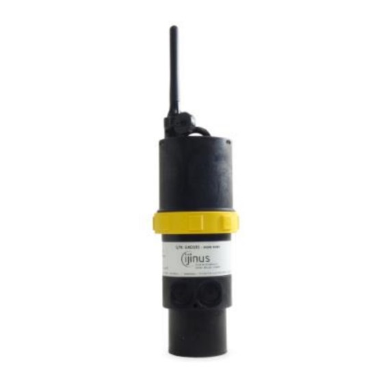
- Page 1 Installation Guide LNU : Battery powered ultrasonic level sensors Measurement of water heights K0J00016-EN-A02 (2019-07-12)
-
Page 2: Table Of Contents
Procedure for inserting the SIM card .......................... 27 Procedure for inserting the SIM card .......................... 28 Instructions concerning ATEX devices ......................... 29 Document History ................................ 30 IJINUS – 25 ZA de Kervidanou 3 – 29300 MELLAC – FRANCE - www.ijinus.com - sales@ijinus.com... -
Page 3: Introduction
LNU sensor : Installation & programming Installation Guide K0J00016-EN-A02 Introduction This solution is an Ijinus product grouping water height measurement by aerial ultrasonic, with automatic measurement cycle changes depending on thresholds, flow rate transformation through conversion tables. Some sensors are equipped with connectors for coupling with an overflow detector or to control water sampler. -
Page 4: Equipment (4 Configuration Examples)
It has internal logger and data can be retrieved on-site (by radio using the programming kit : Wiji). Ultrasonic sensor Lithium battery Programming kit Water sampler cable Overflow detector Fixations: Bracket, fixations either with single or double metal plate with bracket IJINUS – 25 ZA de Kervidanou 3 – 29300 MELLAC – FRANCE - www.ijinus.com - sales@ijinus.com... -
Page 5: Permanent Installation Of A Unique Level Sensor (Continuous Monitoring Or Self-Monitoring Of Water Networks)
(LOG V3) retrieve the data of the level sensors or others and send them by GSM/GPRS. Data logger as a radio/3G access point Other configurations. Actually, the communication protocols available for the Ijinus devices are the following: IJINUS – 25 ZA de Kervidanou 3 – 29300 MELLAC – FRANCE - www.ijinus.com - sales@ijinus.com... -
Page 6: Quick Configuration With The Software Avelour
- The material is considered to be directly functional, the battery can be use directly - All indications contained in this document correspond to programming with Avelour in version 6.04 mini IJINUS – 25 ZA de Kervidanou 3 – 29300 MELLAC – FRANCE - www.ijinus.com - sales@ijinus.com... -
Page 7: First Step : Run Avelour And Connect To The Sensor To Configure
The firmware update can last a moment so it is advised to do it while in your office. On-site prefer the best radio connection (so not if the metal cover of a man hole is closed). IJINUS – 25 ZA de Kervidanou 3 – 29300 MELLAC – FRANCE - www.ijinus.com - sales@ijinus.com... -
Page 8: Third Step : Configuration Of Measures Part
This part is the most important, it allows you to configure your sensor. First of all, and the simplest click on the button “Add”, then choose “Water height”. IJINUS – 25 ZA de Kervidanou 3 – 29300 MELLAC – FRANCE - www.ijinus.com - sales@ijinus.com... - Page 9 Calibration of the water height After clicking the calibration button the bellow windows appears: It is difficult to establish rules but globally 3 cases may arise: IJINUS – 25 ZA de Kervidanou 3 – 29300 MELLAC – FRANCE - www.ijinus.com - sales@ijinus.com...
- Page 10 A calibration in advanced mode will be possible. First check that the sensor is well fronting and perpendicular to the water. positioned, IJINUS – 25 ZA de Kervidanou 3 – 29300 MELLAC – FRANCE - www.ijinus.com - sales@ijinus.com...
-
Page 11: Calibration Of The Sensor Case N°1 (Ideal)
While the measure is temperature compensated, you should calibrate a sensor when temperature are too high and then asking it to measure on a different environment (typical case of 15°C under a IJINUS – 25 ZA de Kervidanou 3 – 29300 MELLAC – FRANCE - www.ijinus.com - sales@ijinus.com... -
Page 12: Calibration Of The Sensor Case N°2 (Classic Example Of A Manhole With An Invert)
The manipulation consists in increasing the value of the pink zone so it covers the different peaks for distances close to the probe, IJINUS – 25 ZA de Kervidanou 3 – 29300 MELLAC – FRANCE - www.ijinus.com - sales@ijinus.com... - Page 13 (3 by default). The average option does an average of those shoots. Most of the time the maximum option is to be chosen to get reliable measurements (and especially in presence of condensation) but also depends of the power setting of the sensor. IJINUS – 25 ZA de Kervidanou 3 – 29300 MELLAC – FRANCE - www.ijinus.com - sales@ijinus.com...
-
Page 14: Calibration Of The Sensor Case N°3 (Complex) - Expert Mode
You can log the temperature thank to the internal T probe used to compensate the level measurement with ultrasonic. For information, the sound speed in the air at 10°C is 337,6m/s. IJINUS – 25 ZA de Kervidanou 3 – 29300 MELLAC – FRANCE - www.ijinus.com - sales@ijinus.com... - Page 15 In the field of ultrasonic, a loss of echoes is reflected by the absence of peaks (or a very weak peaks not detected as an obstacle) on echoes that materialize by a maximal height, the Z you define during the calibration. This function is used IJINUS – 25 ZA de Kervidanou 3 – 29300 MELLAC – FRANCE - www.ijinus.com - sales@ijinus.com...
- Page 16 (here for 1500 mm) with the possibility to integrate mud height, this for a scale every 5 mm). Only the yellow cells have to be filled, conversion is done automatically. IJINUS – 25 ZA de Kervidanou 3 – 29300 MELLAC – FRANCE - www.ijinus.com - sales@ijinus.com...
- Page 17 After the saving operation is done please check that you have at the top right corner the two green sign showing that the sensor working and recording, and also sending data. You can stop them both by pressing the red Stop icon, if needed. IJINUS – 25 ZA de Kervidanou 3 – 29300 MELLAC – FRANCE - www.ijinus.com - sales@ijinus.com...
-
Page 18: Fourth Step : Data Reading In Real Time
“View broadcast measures” (Main menu > Windows > View broadcast measures) View broadcast measures: this option opens a window showing the measures received by radio from Ijinus sensors and loggers nearby. Now you can also press the “Test measure” button for a direct reading f. -
Page 19: Sixth Step: Data Export
Then you need to click the Refresh button to run the test. Simply tick the boxes corresponding to the devices you want to associate. IJINUS – 25 ZA de Kervidanou 3 – 29300 MELLAC – FRANCE - www.ijinus.com - sales@ijinus.com... -
Page 20: Eighth Step : Data Sending
Finally you should run a test by clicking the Launch button to check if the data are sent to our website if your account is created and the sensor already configured. IJINUS – 25 ZA de Kervidanou 3 – 29300 MELLAC – FRANCE - www.ijinus.com - sales@ijinus.com... - Page 21 + icon. Depending on your configuration you may need to choose a minimum delay between 2 anticipated data sending. IJINUS – 25 ZA de Kervidanou 3 – 29300 MELLAC – FRANCE - www.ijinus.com - sales@ijinus.com...
- Page 22 IJINUS – 25 ZA de Kervidanou 3 – 29300 MELLAC – FRANCE - www.ijinus.com - sales@ijinus.com...
- Page 23 Your server administrator can provide to you those information. After completing this chapter please press the Program the devise button, the configuration will be sent by radio to the sensor. IJINUS – 25 ZA de Kervidanou 3 – 29300 MELLAC – FRANCE - www.ijinus.com - sales@ijinus.com...
-
Page 24: Elements For Good Practice And Installation Examples
Finally, below are some photos of sensors installed in different environments: Venturi type channels: Measurement in collectors: IJINUS – 25 ZA de Kervidanou 3 – 29300 MELLAC – FRANCE - www.ijinus.com - sales@ijinus.com... - Page 25 LNU sensor : Installation & programming Installation Guide K0J00016-EN-A02 CSO, SSO applications: Angle adaptor fixation : Install in river: IJINUS – 25 ZA de Kervidanou 3 – 29300 MELLAC – FRANCE - www.ijinus.com - sales@ijinus.com...
- Page 26 Positioning of a Sigfox antenna Positioning of a Sigfox antenna 1 Insertion of GSM / GPRS antenna in the concrete when sensor install under a manhole cover IJINUS – 25 ZA de Kervidanou 3 – 29300 MELLAC – FRANCE - www.ijinus.com - sales@ijinus.com...
-
Page 27: Procedure For Inserting The Sim Card
- Place the lid back (mind the notch) on the threads and screw back the ring to the end. IJINUS – 25 ZA de Kervidanou 3 – 29300 MELLAC – FRANCE - www.ijinus.com - sales@ijinus.com... -
Page 28: Procedure For Inserting The Sim Card
To do so launch the software Avelour, connect to the sensor or logger. Then go to the general menu, > Action > Notify battery changed IJINUS – 25 ZA de Kervidanou 3 – 29300 MELLAC – FRANCE - www.ijinus.com - sales@ijinus.com... -
Page 29: Instructions Concerning Atex Devices
Instructions concerning ATEX devices a. Conformity The sensor type LNU06V3-EX-82-3G can be used in hazardous area for IIB group gases and T4 temperature class for an ambient temperature range from -20°C to +60°C. The device category is 2 and can be used in zone 1 and 2. -
Page 30: Document History
Installation Guide K0J00016-EN-A02 Document History Date Revision Writer(s) Changes 2018-11-09 Creation with document identification from existing user manual 2019-07-12 Adding procedure and image modifications IJINUS – 25 ZA de Kervidanou 3 – 29300 MELLAC – FRANCE - www.ijinus.com - sales@ijinus.com...
Need help?
Do you have a question about the LNU06V3 and is the answer not in the manual?
Questions and answers