
Related Manuals for OHM CORA Series

Summary of Contents for OHM CORA Series
- Page 1 Manchester - England IN K CORA Series Rigging Manual Version 7.0 01/02/2019...
-
Page 2: Table Of Contents
Manchester - England Contents 1. Introduction to CORA ..................2. Safety ......................2.1. General safety ............... 2.2. Load capacity ............... 2.3. Wind load................2.4. Operation ................2.5. pro-A-sync simulation software .......... 3. CORA Array Frame ..................3.1. Introduction ................3.2. Array frame hardware ............3.3. -
Page 3: Introduction To Cora
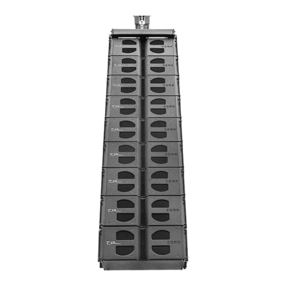
With a dispersion of 100° x 12° and up to 100° x 90° in an array confi guration of 9 boxes, it is capable of 158 dB peak SPL. CORA hardware and its associated components should only be used in conjunction with Ohm CORA line array and CORA-S subwoofer loudspeakers as described in this manual. -
Page 4: Safety
Manchester - England 2. Safety 2.1. General Safety Installation and setup of CORA arrays should be carried out by an Ohm qualifi ed technician. The technician responsible should ensure that all fl ying points and suspensions are suitable for their intended use and pass rigging inspection and safety tests. -
Page 5: Operation
Ohm line arrays must be designed using Ohm’s pro-A-sync simulation software. For optimal alignment, deployment and safety we recommend all users attend one of Ohm’s regularly hosted line array training seminars. Details of Ohm’s training seminars can be found on the Ohm website at www.ohm.co.uk pro-A-sync software is available as a standalone software package for both macOS and Windows based operating systems. -
Page 6: Cora Array Frame
Manchester - England 3. CORA Array Frame 3.1. Introduction The CORA array frame (C-AF) is designed to suspend or ground stack arrays consisting of: CORA line array: CORA-A active line array: CORA-S: A mix of CORA-S and CORA/CORA-A line array. Rear splay link (ground stacking Front link... -
Page 7: Array Frame Hardware
Manchester - England 3.2. Array Frame Hardware The array frame is equipped with all the necessary attachments to allow fl ying or ground stacking of CORA/CORA-A. No additional hardware is required to build fl own array hangs of either CORA/CORA-A or CORA-S. On either side of the frame a front link and a splay link are built into the frame for ease of ground stacking. -
Page 8: Suspension Of The Array Frame
(single or dual pickpoint operation). To determine the correct pickpoint it is recommended to use Ohm’s pro-A-sync simulation software. Failure to do so could result in a fl own array that is not safe, incorrectly aligned for the venue or space you are working in, or acoustically incoherent. -
Page 9: Single Pickpoint Operation
When using a ‘single pickpoint’ the position of the pickpoint is determined by using Ohm’s pro-A-sync simulation software. A one tonne shackle must be used in conjunction with a half metre wire sling to ensure that the chain bag of the hoist being used does not foul on the top of the array frame. -
Page 10: Dual Pickpoint Operation
Pickpoint hole 1 and 13 are used in dual pickpoint operation and the angle of the array calculated using Ohm pro-A-sync. For optimum array vertical alignment an inclinometer should be attached to the frame and the measuring device operated from fl... -
Page 11: Secondary Safety Points
Manchester - England 3.6. Secondary Safety Four x 45° steel tabs at the front and back corners of the array frame allow for a secondary point of safety. The secondary rigging point should be independent of the main rigging point and must be capable of supporting the entire load. From each safety point on the frame one tonne shackles must be used attached to wire slings to form an equilateral triangle maintaining the maximum sling angle of 60°. -
Page 12: Cora Array Setup
Manchester - England 4. CORA Array Setup 4.1. Preparation Before you fl y or ground stack the array you must design the array using Ohm’s pro-A-sync simulation software. This ensures correct acoustical and mechanical deployment of the array. PDF’s can be generated from within the software and printouts made to assist the riggers with the suspension points, chain hoists and pick/pin points. -
Page 13: Cora Array Rigging Mechanism
The splay links on the rear of the cabinet at the top by default are in the storage position. Removal of the pins here allows the splay links to rotate upwards to be connected to the correct alignment hole in the cabinet above according to Ohm’s pro- A-sync software. - Page 14 Manchester - England CORA-S CORA-S utilises separate steel sub links to connect the subwoofer to the array frame or one CORA-S to another CORA-S. Inserting a steel sub link in each corner of the subwoofer allows the connection of the frame on the top or bottom of the cabinet. For mixed arrays of CORA/CORA-A array and CORA-S, two array frames must be used where CORA/CORA-A array cabinets are fl...
-
Page 15: Flown Arrays
Manchester - England 4.3. Flown Arrays Flown arrays are suspended using the C-AF (CORA Array Frame) Once you have chosen the correct type of suspension for your application (single or dual pickpoint) attach the rigging to the frame (as described in chapter 3.4. – 3.5. single/dual pickpoint). -
Page 16: Cora/Cora Active
fl ying link holes on the frame and insert the locking pins of the frame on each side. Using the data from Ohm’s pro-A-sync software rotate up the rear splay links of the cabinet and align them with the correct pin points on the frame. Insert the locking pins on each side of the frame. - Page 17 Manchester - England 6° 4° 2° 0° - 2° - 4° - 6° Once positioned in to the correct GROUNDS TACK FRONT LINK LOCK 6° STORAGE 4° hole as predicted via the pro-A-sync GROUNDS TACK SPLAY LINK 2° 0° STORAGE - 2°...
-
Page 18: Cora-S
Manchester - England 4.5. CORA-S Prepare the fi rst cabinets rigging hardware (as described in chapter 4.2. CORA Array Rigging Mechanism). Lower the frame onto the cabinet until the front and rear sub steel links line up with the fl ying link holes on the frame and insert the locking pins from the cabinet on each side. - Page 19 Manchester - England Add additional subs as follows Position the frame and CORA-S using the hoist over the additional CORA-S. Remove the pins from the top of the sub links on the lower CORA-S if not Y LI G RO O RA already done so.
-
Page 20: Flying A Mixed Cora Array
Manchester - England 4.6. Flying a Mixed CORA Array If CORA-S are to be fl own in a mixed array these must always be positioned at the top of the array column. For a mixed setup two fl ying frames are required, one frame is used for the suspension, the second frame is used beneath the subs to attach CORA/CORA-A array cabinets. -
Page 21: Ground Stacking The Cora Array
Manchester - England 4.7. Ground Stacking the CORA Array Some safety limitations must be considered when ground stacking the array. When using the frame as a ground support a maximum of 8 x CORA/CORA-A array cabinets are allowed to be set up as a ground stack. When using CORA-S as a ground support a combination of 8 x top/sub cabinets as a maximum are allowed to be used as a ground stack. - Page 22 Manchester - England Y LI W eig th e d in Y FR tu re uf ac re d 6° 4° 2° 0° - 2° - 4° - 6° T LI Mixed CORA or CORA-A and CORA-S cabinets in ground stack format.
-
Page 23: Cora Flightcases
Manchester - England 4.8. CORA Flightcases Flightcases for CORA/CORA-A array are available to purchase from Ohm which allows for rapid deployment of the array. Each fl ightcase contains three CORA/ CORA-A Array loudspeakers. With the lid removed from the case, the fl ying frame (once attached to a hoist) can be lowered onto the top of CORA/CORA-A and all three cabinets can be raised at once. -
Page 24: Safety Checks
Manchester - England 5. Safety Checks Before the array is hoisted to its fi nal trim height some safety checks should be made. These checks apply to either fl own or ground stack confi gurations. 5.1. Mechanical Safety Check the attachment of the hoist to the frame. Ensure shackles are tightened correctly. -
Page 25: Flying The Array
Manchester - England 6. Flying the array 6.1. Hoisting the Array Before the array is hoisted always pay attention to the following: The hoists in use must be able to carry the total weight of the array. When hoisting the array be aware of others in the vicinity of the load that are not directly involved in the hoisting process. -
Page 26: Care And Maintenance
Manchester - England 8. Care and Maintenance 8.1. Visual Inspection To eliminate the potential risk of accident due to malfunction, inspection checks must done on all components regularly. Cabinets: Visual inspection of all cabinet hardware for signs of obvious damage, cracks or corrosion. -
Page 27: Technical Specifi Cations
Passive - 1.15 kHz with dispersion control Impedance phase response 2 x 8 Ohm, minimum 7 ohms @ 321Hz LF / 7.5 Active - * LPF - 1 kHz LF ohms @ 600Hz HF HPF - 1.15 kHz HF /60 Hz Full... - Page 28 Manchester - England CORA Array Cabinet Drawing Front Side Back 632mm 576mm 300mm Bottom Version 7.0 01/02/2019...
-
Page 29: Cora-A Array
C-AF CORA array frame Ohm DSP solutions Additional Descriptive Data Input connection Birch plywood construction, with durable Balanced XLR input, 10 K ohm Impedance with scratch resistant black polyurea paint fi nish parallel link output with Ohm logo. Protection Recommended fi lter settings are available on Internal multiband peak and RMS limiter, the website ohm.co.uk/downloads... - Page 30 Manchester - England CORA-A Array Cabinet Drawing Front Side Back 632mm 576mm 300mm Bottom Version 7.0 01/02/2019...
-
Page 31: Cora-S
Manchester - England 9.3. CORA-S Cabinet Design HPF - 29 Hz 1 x 15” Subwoofer, refl ex loaded subwoofer Impedance 8 Ohm, minimum 6.6 @ 146 Hz Connectors Power Handling (AES) 4 x 4 pole speakON connectors ® 850 Watts (continuous) Dimensions (H x W x D mm) Max. - Page 32 Manchester - England CORA-S Cabinet Drawing Front Side Back 630mm 572mm Bottom Version 7.0 01/02/2019...
-
Page 33: Manufacturers Declaration
Manchester - England 10. Manufacturers Declaration Aural Ltd. (Ohm) hereby declare that the equipment described below is designed, built and sold by us in such a way as to comply with the relevant fundamental safety and health criteria of the applicable EC Directive(s). This declaration shall cease to be valid if alterations are made to the equipment without our prior agreement. - Page 34 Manchester - England aural ltd Wellington Close • Parkgate Industrial Estate • Knutsford •Cheshire • WA16 8XL • United Kingdom • Tel: +44 (0)1565 654641 Email: info@ohm.co.uk • Website: www.ohm.co.uk Version 7.0 01/02/2019...
Need help?
Do you have a question about the CORA Series and is the answer not in the manual?
Questions and answers