Advertisement
Available languages
Available languages
Quick Links
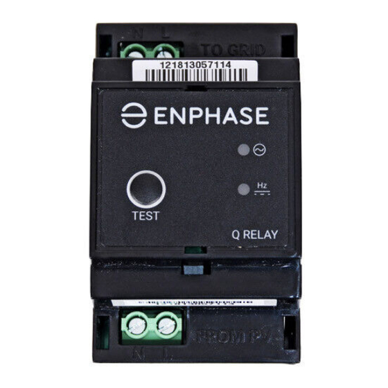
Q R E L A Y ( m u l t i p h a s e ) I N S T A L L A T I O N
SPECIFICATIONS
Over voltage category (EN 61010-1)
III
CAT III
GRID terminal is rated for
measurement category III
Pollution degree (EN 61010-1)
2
Supply range
85 to 265 VAC
Nominal input frequency
50 Hz
Voltage and frequency acquisition
100 ms (5 line cycles @ 50Hz)
time on valid input during normal
operation
Output
4-pole normally open relay (L1, L2,
L3 & N)
Output power rating
6 kVA per phase
Output rating (typical)
240 VAC, 25A
Power consumption
18 VA
Conducted and radiated EMI
IEC 61326, BS EN 50065-1 & 2-2, BS
EN 61326-1&2, BS EN 61000-3-11&12
Operating temperature range
-40 °C to 50 °C
Altitude rating
2000m
IP rating
IP 20 (must be in protected
environment)
Relative humidity
0 to 95 non-condensing
PREPARATION
In Enphase installations, the multiphase Q Relay (network system
relay controller) acts as a galvanic disconnection device. It is designed
for three-phase or multiphase use and has built in contactors. During
specified grid abnormalities, the Q Relay disconnects the Enphase
Microinverters from the AC grid, and when the voltages return to normal
and the grid frequency is in the acceptable range, the Q Relay reconnects
the microinverters to the AC grid. The Q Relay has built in current sensing
that can detect DC current injection required by CEI 0-21 requirements.
The Q Relay works together with the Envoy-S to meet the need to break
lines and neutral per grid requirements.
See full installation instructions for the Enphase Envoy-S and/or En-
phase Microinverters at: enphase.com/support.
It is best practice to install the Q Relay when installing the Envoy-S and
before commissioning the system.
The Q relay is IP-20 rated and supports 25A per phase.
You must mount it in an environmentally protected enclosure. Typically
this is a switchboard.
You must also use 2.5 - 6.0 mm² conductors for relay connections.
INSTALLATION
+
DANGER: Risk of electric shock. Always open or disconnect
circuit from power-distribution system (or service) of building
and PV side before installing or servicing the Q Relay.
A ) Install the Enphase Envoy-S as directed in the Envoy-S Quick Install
Guide.
B ) Install the Q Relay in a protected environment (e.g., switchboard)
on a 35 mm DIN rail near the Envoy-S.
+
DANGER: Risk of electric shock. The Q Relay is intended for
installation in an electrical enclosure (i.e. switchgear) that
prevents Operator access to hazardous live parts.
C ) Connect the Line and Neutral conductors (2.5 - 6.0 mm² ) from
the PV system to the "FROM PV" terminals of the Q Relay so that
the Neutral is on the N terminal and the Lines connect to the L1,
L2, and L3 terminals.
D ) Connect a Neutral conductor (2.5 - 6.0 mm² ) from the "TO GRID"
N terminal of the Q Relay to the Neutral busbar.
© 2021 Enphase Energy. All rights reserved. Enphase, the Enphase logo, Enpower smart switch, Encharge storage system, IQ Envoy, IQ combiner,
IQ microinverter, Installer Toolkit, Enlighten and other trademarks or service names are the trademarks of Enphase Energy, Inc. Data subject to
change. 2021-05-31
E ) Connect the Line conductors (2.5 - 6.0 mm²) from the "TO GRID"
L terminal of the Q Relay to an EN/IEC/AS/NZS 60947-2 approved
circuit breaker, rated for no more than 20A.
*
WARNING: The circuit breaker must be suitably located and
easily reached. It must also be marked as the disconnecting
device for the PV system.
F ) Tighten all relay terminal connections to 0.85 N m.
G ) Energise the circuit.
H ) Upon power up, the LEDs should all turn green to indicate the AC
voltage and frequency are within specification of the grid code.
See the LED states table.
I ) Use the Enphase Installer Toolkit to apply a grid profile to the Q
Relay and microinverters. Do not skip this step.
PROGRAM FOR 1 or 2 PHASE
OPERATION
The 3-phase Q-Relay can also support 2-phase and single-phase
applications. To program the number of phases:
A ) Press and hold the test button. The phase voltage indicators (V1,
V2, V3), will turn red and the relay will click. After approx. 6 sec-
onds the phase voltage LEDs will start flashing red. The number
of red LEDs flashing corresponds to the number of phases. A
sequence of 3, then 2, then 1 flashing LEDs is repeated.
B ) Release the test button when the appropriate number of LEDs
are flashing.
NOTE:
The selected mode will persist through power cycling.
•
The selected number of phases must be connected in sequence
•
starting at L1.
All options must include a Neutral.
•
In some installations the Q-Relay may trip due to DCI during
•
commissioning while it is learning the system size. This may
occur when commissioning on cloudy days and is considered
normal operation.
AUTO TEST
Section A.4.4 of CEI 0-21 : 2019 requires an Autotest to be performed.
This can be initiated by pressing the test button on the Q-Relay for
less than 2 seconds. The results of the test will then be available
via the Enlighten platform for homeowners and installers within 30
minutes of the test being completed. During the test the LEDs can be
observed to cycle Red, and if the test passes, the Q-Relay device will
re-enter service. If the test fails, the Frequency/DCI LED will flash Red
continuously.
NOTE: The unit should have been properly powered up and configured
for greater than 10 minutes before starting the test.
Advertisement

Subscribe to Our Youtube Channel
Related Manuals for enphase Q RELAY


Summary of Contents for enphase Q RELAY
- Page 1 N terminal of the Q Relay to the Neutral busbar. © 2021 Enphase Energy. All rights reserved. Enphase, the Enphase logo, Enpower smart switch, Encharge storage system, IQ Envoy, IQ combiner, IQ microinverter, Installer Toolkit, Enlighten and other trademarks or service names are the trademarks of Enphase Energy, Inc. Data subject to...
- Page 2 DANGER: Risk of electric shock. Risk of fire. Do not attempt to re- pair the Q Relay; it contains no user-serviceable parts. Tampering with or opening the Q Relay will void the warranty. Warranty void if cover removed. If the Q Relay fails, contact Enphase Customer Support for assistance (http://enphase.com/global/contact/).
- Page 3 GRID” del Relè Q alla barra di distribuzione del Neutro. © 2021 Enphase Energy. Tutti i diritti riservati. Enphase, il logo Enphase, l'interruttore intelligente Enpower, il sistema di accumulo Encharge, IQ Envoy, IQ Combiner, IQ Microinverter, Installer Toolkit, Enlighten e altri marchi o nomi di servizi sono marchi di Enphase Energy, Inc.
- Page 4 FV prima di installare o riparare il Q Relay. PERICOLO: Rischio di scosse elettriche. Non utilizzare l'apparec- chiatura Enphase in modo difforme dalle istruzioni del costrut- tore, onde evitare decessi o lesioni a persone oppure danni alla strumentazione.
Need help?
Do you have a question about the Q RELAY and is the answer not in the manual?
Questions and answers