
Subscribe to Our Youtube Channel
Related Manuals for ZOJE ZJ-5780S


Summary of Contents for ZOJE ZJ-5780S
- Page 1 ZOJE ZJ-5780S Computerized Controller for High Speed Buttonhole Machine Owner’s Manual Forewords...
- Page 2 Thanks for using the Computerized Buttonhole Control System. It is appreciated that you do read this manual carefully in order to operate the machine correctly and effectively. If the user operates the machine contrary to regulations, thus cause loss to user or third party, we will not take responsibility.
-
Page 3: Table Of Contents
Contents 1 General Information 1 1.1 General........................1 1.2 Functions and Parameter Index................1 1.3 Standardization......................2 1.4 Operation Method....................2 2 Operating Instruction 2.1 Name and Description of Each Part on SC500.............2 2.2 Buttons used in common on SC500..............3 2.3 Basic Operations....................4 2.4 Operation of Normal Pattern..................5 2.5 Pattern Registration....................8 2.6 Copy a Pattern.......................9 2.7 Name a Pattern....................10... - Page 4 4.5 Edit pattern for cycle stitching................58 4.6 Change the clothes for sewing................59 5 Interface for Cycle Stitching 60 5.1 Instruction on Functions..................60 6 Interface for Continuous Stitching Data Input 6.1 Instruction on Functions..................62 6.2 Select Pattern for Continuous Stitching...............63 6.3 Pattern Edition for Continuous Stitching..............63 7 Interface for Continuous Stitching 66 7.1 Instruction on Functions..................66 8 Communication Function 67...
-
Page 5: General Information
1 General Information 1 General Information 1 General Information 1 General Information 1.1 General SC500 Series Computerized Control System for Sewing Machine is characterized by the advanced technology it adopted. Its main shaft motor features large torque, high efficiency, stable running and low noise by adopting the advanced AC Servo Control Technology;... -
Page 6: Standardization
Input Voltage AC175V~AC265V Motor Minitype AC servo motor 400Wdirect driving Figure measurement Machine tool width 185mm、Height 364mm、Length 630mm Machine head weight 55Kg Machine type specification S:Standard K:Knitting specification Presser Foot 1 Presser Foot 2 Presser Foot 3 Presser Foot 5 Width 3-10mm(Random setting) Length of Sewing... -
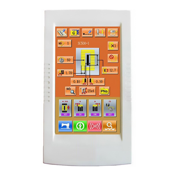
Page 7: Buttons Used In Common On Sc500
Touch Panel • LCD Displayer 1 1 1 1 READY key → Changeover of the data input screen and the sewing screen can be performed. 2 2 2 2 INFORMATION key → Changeover of the data input screen and the information screen can be 3 3 3 3 performed ④... -
Page 8: Basic Operations
Plus Button → Increase the value of data. Reduction Button → Decrease the value of data. Reset Button → Enable the release of error. Numeral Input Button → Display ten keys and enable input of numerals 2.3 Basic Operations ① ① ① ① Turn on the power First, make sure that the set presser type (A) is the same as that of the presser actually mounted . -
Page 9: Operation Of Normal Pattern
③ ③ ③ ③ Set Set machine to sewing possible state to sewing possible state to sewing possible state to sewing possible state Press READY key (C). The back-light of LCD displayer changes to blue color and the machine is ready for sewing. - Page 10 Instruction of Function Keys: : : : Figure Function Remarks Register the Pattern Copy the Pattern Name the Pattern Thread (Lower the presser The needle Can be changed foot ) Winding Select Pattern Enter Pattern Selection Interface Set Needle Thread Tension S52 and S56 will be influenced by the data switch of sewing.
- Page 11 ( ( ( ( 2 2 2 2 ) ) ) ) Interface of Sewing Press to enter the Sewing Interface shown as the figure at right. For detailed functions please take the Instruction of Function Keys for reference. Instruction of Function Key: : : : Figure Function Remarks...
-
Page 12: Pattern Registration
Display Right Width of Knife Groove Display Length of Cloth Cutting Display single stitching/ double stitching Display Numbers of Basting Display the Total Number of stitches Display the Sewing Speed at present Display value of counter :sewing counter :No. of piece counter Set Speed Display of Customer Management 2.5 Pattern Registration... - Page 13 Select the 1st bar-tacking section Select the 1st bar-tacking section shape shape Select the 1st bar-tacking Select the 1st bar-tacking section section shape shape 2 2 2 2 After determined the pattern number, user can press to enter the interface for selecting the 1st bar-tacking shape (as shown in right figure).
-
Page 14: Copy A Pattern
2.6 Copy a Pattern ① ① ① ① select the pattern wanted Press to enter the interface for copying the pattern (as shown in right figure). Among the registered patterns, select the pattern number of the copied one and press ②... -
Page 15: Name A Pattern
2.7 Name a Pattern Press to enter the interface for naming the pattern (as shown in the right figure), 14 figures can be inputted at the most. :Icon Right-moving :Icon Left-moving :Eraser Select the figure wanted, press to end the operation of naming the pattern. -
Page 16: Winding
2.9 Winding ① ① ① ① Set the bobbin Set the bobbin Set the bobbin Set the bobbin Fit a bobbin fully onto the bobbin winder shaft. Then push the bobbin thread guide in the direction of the arrow mark (as shown in the figure in right). -
Page 17: Select The Type Of Presser
2.10 Select the Type of Presser ① ① ① ① Display the data input screen Display the data input screen Display the data input screen Display the data input screen Only in case of the data input screen (orange), the contents of setting can be changed. -
Page 18: Select A Pattern
2.11 Select a Pattern Press to enter the interface of pattern selection (as shown in the right figure), the upper area shows the shape and relevant data of the selected pattern while the lower area shows the registered number the pattern. :Input the number to inquire pattern :Delete the pattern ①... -
Page 19: Selection Of Sewing Shape
2.12 Selection of Sewing Shape 2.12 2.12 2.12 Press to enter the interface of selecting the sewing shape. ① ① ① ① Select the 1 bar-tacking section The five shapes of 1 bar-tacking section are: Square Type, Radial Type, Eyelet Type, Semi-lunar Type and the Round Type. - Page 20 Remark 2 : : : : The patterns of No.27, No.28, No.29 and No.30 are available only when the K04 is set to “30 shapes”. ④ ④ ④ ④ Sewing Shape List 01 Square type 02 Round type 03 Radial square 04 Radial type 05 Radial straight type...
-
Page 21: Set Data For Sewing
2.13 Set Data for Sewing ① ① ① ① Modification of the sewing data Press to enter the interface of setting sewing (as shown in the figure at right). Select the sewing data you wish to modify and then enter the setting status. The data with purple as its background is the parameters of data input type, while those with blue background are the parameters of pattern selection type. - Page 22 Select to enter the interface.(as shown in the right figure) ② ② ② ② Data Table of Sewing The sewing data is related to the selected shape. Different in shapes, the different in sewing data could be set. Meanwhile the initial value of sewing data might be different as well. Under the Mode &...
- Page 23 Over-edging width, left 0.10~5.00 0.05mm This item sets the over-edging width of left parallel section. Ratio of right and left shapes 50~150 This item sets enlargement/reduction ratio of right side shape making the knife position as the center Pitch at parallel section 0.200~2.500 0.025mm This item sets sewing pitch of left and right parallel sections...
- Page 24 Eyelet width 1.0~10.0 0.1mm Remark 1 This item sets crosswise size of the inside of eyelet shape. Actual needle entry point is the dimension to which S04 Knife groove width, left is added. Eyelet length 1.0~10.0 0.1mm Remark 1 This item sets lengthwise size of the inside of eyelet shape. Round type shape length 1.0~5.0 0.1mm...
- Page 25 stitching :Double stitching :Cross stitching Compensation of double stitching width 0.0~2.0 0.1mm Remark 3 This item sets amount to narrow over-edging width of 1st cycle when setting double stitching Number of times of basting 1 次 This item sets number of times of basting :Without Basting :1~9 times Basting pitch...
- Page 26 Sewing together function This item selects the function when performing sewing together first. : Without sewing :With sewing together Together; When "With sewing together" is selected: Sewing is performed in the order of sewing together -> basting -> normal sewing. Width of sewing together 1.0~10.0 0.1mm...
- Page 27 Setting of needle thread tension of basting 0~200 Remarks This item sets needle thread tension of basting. ACT timing adjustment at the start of 1 bar- -5~5 1stitch Remarks tacking This item adjusts needle thread tension output start timing at 1st bar-tacking section. ACT timing adjustment at the start of right over- -5~5 1stitch...
- Page 28 Crosswise compensation of tie stitching at the end 0.0~2.0 0.1mm Remarks of sewing This item sets start position of tie stitching in crosswise direction at the end of sewing. Knife motion This item sets "With/without motion" of normal cloth cutting knife. :Normal knife motion off :Normal knife motion on Knife motion at 1st cycle of double stitching...
-
Page 29: Direct Selection Of Pattern
2.14 Direct Selection of Pattern The user can register the 10 frequently used patterns to the direct keys for selecting directly, press to enter the interface of selecting as shown below. 2.15 Trail Sewing ( ( ( ( 1 1 1 1 ) ) ) ) Display the interface of sewing At data input interface, press , the background of screen will change to blue, and the system enter the interface of sewing. -
Page 30: Set Needle Thread Tension
At the sewing interface, press to enter the interface of trail sewing (as shown in the right figure) . :Return to origin :Backward :Forward :Thread tension at stitch point :Amount of stitches at present/ Total amount :Sewing order key :Thread trimming order key :Jump feed order key :Set thread tension :Drive Knife key... - Page 31 Display the data input screen Display the data input screen Display the data input screen Display the data input screen 1 1 1 1 Only in case of the data input screen (orange) or sewing screen (blue), needle thread tension can be changed.
-
Page 32: Operation Of Counter
Set value on panel In case of the radial eyelet shape, ○ ○ ○ ○ Initial Initial Initial Initial set the bar-tacking value value value value tension first to Purl stitch 1.Parallel Crest is lowered Crest is raised 120 120 120... -
Page 33: Stop In Emergency
Display the counter Display the counter interface interface Display the counter Display the counter interface interface 1 1 1 1 In the sewing interface, press ( ),the interface of counter setting comes out. :sewing counter :No. of pieces counter The user can set the type of counter by choosing , and set the value of counter。... -
Page 34: Interface Of Parameter Setting Mode
Press to release the error. And the interface of single-step motion comes out (shown as the figure at right) The operation is same as the operations in trail sewing. Depress the pedal and sewing starts again. 3 3 3 3 Interface of Parameter Setting Mode Press to shift the interfaces of Data Input and Mode (as shown in the right figure), and detailed... -
Page 35: Instruction On Functions
Mode Setting Level 2 Interface Mode Setting Level 3 Interface 3.1 Instruction on Functions Figure Function Remarks Set parameters in Level 1 Set counters Set type of sewing Set user management items Set P pattern Initialize U disk Inquire software version Keyboard lock Edit sewing data Aging test... -
Page 36: Set Parameter Of Level 1
Brightness adjustment Set parameters in Level 2 3.2 Set Parameter of Level 1 ① ① ① ① Operation of parameter setting Select to enter the interface of Level 1 parameter setting (shown as the figure at right). Select the parameter you wish to modify. The parameters with purple background are the parameters of data input type while the parameters with blue background are the parameters of figure... - Page 37 Parameter Set arrange Unit in Edit Initial set Presser Presser up to Presser Presser up to up to maximum position up to maximum position maximum position maximum position 0~17.0 0.1mm 14.0mm Height of maximum position of pedal operation is set. Presser up to intermediate position 0~14.0 0.1mm...
- Page 38 Soft-start speed setting 3rd stitch 400~4200 100rpm 2000rpm Soft-start speed setting 4th stitch 400~4200 100rpm 3000rpm Soft-start speed setting 5th stitch 400~4200 100rpm 4000rpm Type of presser Type 1 (Type 1,2,3,5) Presser size width (Type 5) 3.0~10.0 0.1mm 3.0mm When type 5 of U14 Kind of presser is set, input the width.
- Page 39 :Ineffective :Effective Selection of presser position at the time of ON of READY key Set presser foot position when READY key is pressed :up :down Selection of presser position at the time of completion of 1-cycle. Set presser foot position when 1-cycle is completed.
-
Page 40: Set Parameter Of Level 2
available U50 Control Panel Voice available U50 Voice of Control Panel and buzzer available U200 Language setting Chinese English and Chinese available. 3.3 Set Parameter of Level 2 ① ① ① ① Operation of parameter setting In the interface of Mode Setting Level 3, press enter the interface for setting parameters of Level 2 (as shown in the right figure). - Page 41 1-pedal (With intermediate : position) Prohibition on selection of Presser type Changes Permitted :prohibit to change :permit to change Selection sewing shape 12 shapes level (12/20/30) registered shapes exceed 12 or 20, then parameter K04 shall not be 12 or 20 Cloth cutting knife power Set output power of cloth cutting knife Selection of machine type...
- Page 42 Without output : Function of origin retrieval each time Origin retrieval is performed after completion of sewing. Without : After the end of sewing : :after the end of cycle Needle up by reverse run Effective When U01 Presser lifter maximum position is set to 14.0 mm or more, motion of needle up by reverse run is automatically performed and the machine stops.
- Page 43 Needle-rocking motor origin -10~10 compensation pulse(0.05mm ) Presser lifter motor origin -100~10 compensation pulse(0.05mm ) Display of direct button Non-displayed :Non-displayed :Displayed Thread trimming on the way in Permission continuous stitching In case of prohibited, jump feed setting becomes invalid, and the registered pattern is sewn at the same position.
- Page 44 Adjustment on sensitivity of button K190 Restore to original parameters K200...
-
Page 45: Counter Setting
3.4 Counter Setting... - Page 46 Press to enter the interface for counter setting(as shown in the right figure) Set the existing value and the set value of 1 1 1 1 counter A is the existing value of the counter. Press that figure to enter the interface for setting existing value of counter.
-
Page 47: Edition Of Sewing Data
:Compensation of bar-tacking width, right; :Setting of needle thread tension at the start of sewing 3.6 Edition of Sewing Data Some sewing data can be set to be opened, press to enter the interface of sewing data edition interface under the Mode Setting Level 2 (as shown in the right figure). -
Page 48: Changing Sewing Mode
3.7 Changing sewing mode Press to enter the interface of sewing type selection (as shown in the right figure). :normal sewing : continuous stitching : cycle stitching After confirming the sewing type, press to end the operation. Press , then the data input interface of the selected sewing type is displayed. -
Page 49: Inspection Mode
10 pattern numbers can be registered to the direct buttons at most. On 10 displayed direct buttons, the user shall press the button he wishes to register, and then enter the pattern select interface. (as shown in the right figure) :Pattern inquiry :Delete the existing registered pattern :confirm the selection... - Page 50 ( ( ( ( 1 1 1 1 ) ) ) ) Adjustment of upper thread trimming ① ① ① ① Adjusting method In the interface of Mode of Inspection, press ( I01 upper thread trimming ) to enter the adjustment interface of upper thread trimming(as shown in the right figure):...
- Page 51 ( ( ( ( 2 2 2 2 ) ) ) ) Adjustment of down thread trimming ① ① ① ① Adjusting method Under the Mode Inspection interface, press (I02 down thread trimming) to enter the adjusting interface of lower thread trimming (as shown in the right figure).
- Page 52 ( ( ( ( 3 3 3 3 ) ) ) ) Testing method of inputted signal Under the interface of Inspection Mode, press (I03 Input Inspection),to enter the interface of input inspection interface (as shown in right). Users can confirm the input status of each switch and sensor.
- Page 53 ( ( ( ( 4 4 4 4 ) ) ) ) Inspection of LCD Display In the interface of Mode Inspection, press (I04 Inspection of LCD Display) to enter the interface of LCD Display Inspection (as shown in right figure). Check whether the LCD fades in that status.
- Page 54 ( ( ( ( 6 6 6 6 ) ) ) ) Methods for Output Inspection In the interface of Mode Inspection, Press (I06 Output Inspection) to enter the interface of Output Inspection (as shown in the right figure). The output status of the solenoid can be checked under that interface.
- Page 55 ( ( ( ( 8 8 8 8 ) ) ) ) Continuous Running ① ① ① ① Display the interface for continuous running In the interface of Mode Inspection, Press (I08 continuous running)to enter the interface of continuous running (as shown in right figure). :Action interval :Gusseting origin inspection :Presser foot Up/Down times...
-
Page 56: Brightness Adjustment
3.10 Brightness Adjustment In the Mode Setting Level 2 interface, press enter the interface for brightness adjustment (as shown in right figure), the brightness value can be adjusted from 0 to 100 by pressing , it also can be adjusted by inputting the value via keyboard and then pressing 3.11 Operation of Keyboard Lock In the Mode Setting Level 2 interface, press... - Page 57 can see there is a figure to show the locking status under the pattern number. Only can the available figures shown under the status of keyboard locking. ③ ③ ③ ③ Scope of locking keyboard 1.Normal sewing data input interface: 1)...
-
Page 58: Initialize U Disk
3.12 Initialize U disk In the Mode Setting Level 2 interface ,press enter the interface of Initialize U disk. Press to delete all datas in U disk. -
Page 59: Data Of Cycle Stitching Input Interface
4 Data of Cycle Stitching 4 Data of Cycle Stitching I I I I nput Interface 4 Data of Cycle Stitching 4 Data of Cycle Stitching nput Interface nput Interface nput Interface This function is to sew the plural sewing pattern data in order in cycle. -
Page 60: Pattern Registration
Select clothes for sewing Modify sewing data 9~12 Key for moving icon key for selecting pattern Key for deleting sub- Delete the sub-pattern selected by the icon pattern Key for deleting all sub- Delete the entire sub-pattern in the existing cycle patterns stitching data Sewing order... -
Page 61: Copy A Pattern
4.3 Copy a Pattern ① ① ① ① Select the pattern wanted Press to enter the interface of Pattern Copy (as shown in right figure). Select the wanted pattern amount the registered ones and then press ② ② ② ② Input the number of the newly registered pattern The upper area shows the copied pattern, select a unregistered number for it. -
Page 62: Select The Patterns For Cycle Stitching
4.4 Select the patterns for cycle stitching Press to enter the interface of selecting the pattern for cycle stitching (as shown in right figure). The operation is same to the operation of normal pattern selection. 4.5 Edit pattern for cycle stitching ①... - Page 63 Modification in sewing data 2 2 2 2 Move the icon to the target pattern, press to enter the interface for sewing data setting (as shown the figure below). Left figure is the modifications on sewing data of The right figure is the edition on the data of normal pattern.
-
Page 64: Change The Clothes For Sewing
4.6 Change the clothes for sewing Press to enter the interface for selecting the clothes for sewing (as shown in right figure).In this section, the user can modify the reference design in the interface of sewing data input. 5 Interface for Cycle Stitching 5 Interface for Cycle Stitching 5 Interface for Cycle Stitching 5 Interface for Cycle Stitching... -
Page 65: Instruction On Functions
5.1 Instruction on Functions Figure Functions Remarks Trail sewing Knife function Shift the Knife function Thread (lower the presser) Winding Pattern number display Needle thread tension setting Display Left Over-edging Width Display Left Width of Knife Groove Display Right Width of Knife Groove Display Length of Cloth Cutting Display single stitching/ double stitching Display Numbers of Basting... -
Page 66: Interface For Continuous Stitching Data Input
Sewing order No. Sewing serial Pattern number display Sewing order 6 Interface for Continuous Stitching Data Input 6 Interface for Continuous Stitching Data Input 6 Interface for Continuous Stitching Data Input 6 Interface for Continuous Stitching Data Input Without lifting the presser it is able to sew up to as many as 6 shapes continuously . -
Page 67: Select Pattern For Continuous Stitching
Select pattern for Continuous stitching Key for deleting all sub-patterns Delete the entire sub-pattern in the existing continuous stitching data Sewing order Clothes Feeding Amount Input Key Sub-pattern Select Key Sewing data edition 6.2 Select Pattern for Continuous Stitching Press to enter the interface for selecting the pattern (as shown in right figure). - Page 68 Figure 2 Figure 1 Select pattern 3 3 3 3 Press to enter the interface for selecting pattern (as shown in right figure).
- Page 69 Select proper pattern, press confirmation and press to delete the present pattern. Modification on sewing data 4 4 4 4 Press to enter the interface for setting sewing data (as shown in the right figure).
- Page 70 7 Interface for Continuous Stitching 7 Interface for Continuous Stitching 7 Interface for Continuous Stitching 7 Interface for Continuous Stitching Press to enter the interface for sewing (as shown in right figure). 7.1 Instruction on Functions Figures Functions Remarks Trail sewing Knife function Shift knife functions Thread (lower the presser)...
-
Page 71: Communication Function
Display Right Width of Knife Groove Display Length of Cloth Cutting Display single stitching/ double stitching Display Numbers of Basting Display the Total Number of stitches Display the Sewing Speed at present Display value of counter :sewing counter :No. of piece counter Speed setting Pattern number inputted into continuous stitching data Sewing shape display... -
Page 72: Take-In Of The Data
8.2 Take-in of the Data ① ① ① ① Display the communication interface Press Communication Key (A) in the data input interface, then the communication interface will be displayed Select the type of data 2 2 2 2 Press data selection key (B), then the interface of data display is shown. - Page 73 ⑤ ⑤ ⑤ ⑤ Operation of writing data from U Disk to panel ( ( ( ( 1 1 1 1 ) ) ) ) Select pattern from U disk Press to enter the interface for selecting pattern from U disk. Select the data file you want to input.
- Page 74 ( ( ( ( 3 3 3 3 ) ) ) ) Start Communication Press Communication Key (L) to begin data communication. After the communication, the system will return to the interface of communication. ⑥ ⑥ ⑥ ⑥ Operation of writing data from panel to U Disk Press to carry out the Operation of writing data from panel to U Disk.
-
Page 75: Instruction For Updating
( ( ( ( 2 2 2 2 ) ) ) ) Start communication Press Communication Key (L) to begin data communication. After the communication, the system will return to the interface of communication. The pattern copied to U Disk will be named as SC- 5xx.EDP or SC-5xx.VDT. -
Page 76: Information Function72
② ② ② ② Select type of updating Press to enter the selecting status of communication, then press , at last press confirmation. :Panel update key Select the update file 3 3 3 3 Press to choose the updating file, press confirm Press to start updating. -
Page 77: Checking The Repair And Inspection Information
well by the function to display the target output and the actual output. 9.1 Checking the Repair and Inspection Information ① ① ① ① Display the information interface Press the information key (A) at switch seal Section in the data input screen, the interface of information will be displayed . -
Page 78: Input The Maintenance And Repair Time
Information on the following three items is displayed in the repair and inspection information screen :Needle replacement (1,000 stitches) : : : : Cleaning time (hour) : : : : Oil replacement time (hour) The interval to inform of the inspection for each item in key (C) is shown at D, and remaining time up to the replacement is displayed at E. - Page 79 ② ② ② ② Display the maintenance and repair interface. Press maintenance and repair key (B)in the information interface. ※ In the interface of maintenance level, there are two keys at the lower side, whose descriptions are as followed: :Warning Record :Running Record ○...
-
Page 80: Method To Release The Warning
Set item for maintenance and repair 4 4 4 4 Set the set value of the maintenance & repair item at 0, the system will stop the function of maintenance and repair. Input the set value of the maintenance and repair item, via the numeral keyboard, and then press for confirmation. - Page 81 Display of production control interface 3 3 3 3 Press the production control interface display key (B) in the information interface to enter the interface of production control (as shown in right figure). There are five items displayed on the interface of production control as below: A:Target value at present A:...
-
Page 82: Information Of Production Control Setting
thread trimming is set as 2, the actual value will be calculated at every two progresses. The rest is done in the same manner. If the number of thread trimming is set as 0, no calculation will be carried out. 9.4.2 Via Sewing Interface 9.4.2 9.4.2... - Page 83 Input value of final target 4 4 4 4 At first, please input the number of production target pieces in the process to which sewing is performed from now on. Press the Final Target Value Key to enter the interface of final target value. Press the numeral keys or the plus button and reduction button to input the figure you want, and then press...
- Page 84 Input the number of thread trimming 6 6 6 6 Then, please input the average number of thread trimming in one process. Press the Number of Thread Trimming Key to enter the interface for inputting number of thread trimming. Press the numeral keys or the plus button and reduction button to input the figure you want, and then press for confirmation.
-
Page 85: Display The Threading Diagram
Clear the counted value 9 9 9 9 When clearing the counted value, make sure the counter is stopped, and then press Clear The present target value and the actual value can be cleared. (Note:The Clear Key can only be displayed at he counter stopping.)... -
Page 86: Warning Record
9.7 Warning Record In the interface of maintenance level, press the inquire the warning records. For example , , EB301 is the problem code,7 is the times of warning. Press to check the details of the warning. 9.8 Running Record In the interface of maintenance level, press to check the running information of the machine. -
Page 87: Operation Of Vdt Pattern
10 Operation of VDT Pattern 10 Operation of VDT Pattern 10 Operation of VDT Pattern 10 Operation of VDT Pattern The patterns in VDT Type can be generated by using the pattern-making software. After the pattern was inputted into the memory from the U Disk, the interfaces of data input and sewing are displayed as below: Press to enter the interface for setting the sewing... - Page 88 Data Table for Sewing VDT Patterns: : : : Items range Unit Initial value Knife groove width, right -2.00~2.00 0.05mm This item sets the clearance between cloth cutting knife and right parallel section. Knife groove width, left -2.00~2.00 0.05mm This item sets the clearance between cloth cutting knife and left parallel section.
-
Page 89: Appendix
Tension reference value 0~200 11 Appendix 11 Appendix 11 Appendix 11 Appendix 11.1 Warning List Warning No. Warning Name of Problem How to recover Display Pedal not at intermediate Position. Self-recovery EB001 Emergency stop EB002 Press Main voltage(300V)too low Turn off the machine EB004 Main voltage(300V)too high Self-recovery... - Page 90 Thread break detector error EB017 Press Knife position error Turn off the machine EB018 Emergency stop switch not at Self-recovery EB019 proper position Confirmation of tilt of machine Turn off the machine EB020 head Panel is connected to the machine Turn off the machine EB024 other than supposed...
- Page 91 Knife can’t return EB037 Press Knife sensor error EB038 Press Non-exist the pattern EP301 Press Pattern file data error EP302 Press No pattern in memory EP303 Press Can’t delete existing pattern EP304 Press Capacity of memory is too low. EP305 Press Delete the last pattern EP306...
- Page 92 Failure to read update file from U EP314 Press Disk Calculation over sewing area EP315 Press Tie stitching presser size error at EP316 Press sewing end Tie stitching presser size error at EP317 Press sewing start Initialization error EP318 Press Prohibit to input EP319 Press...
-
Page 93: Hint List
Presser size error (Left) EP329 Press Presser size error (Left &Right) EP330 Press Eyelet knife length error EP331 Press Eyelet shape length error EP332 Press Calculation error EP333 Press Flow bar-tacking compensation EP334 Press error Failure in software update Turn off the machine EP335 Low battery EP336... -
Page 94: Original Data List
Hint of Copy All the Patterns From U Disk to Panel M004 Hint of Write All the Patterns From Panel to U Disk M005 Hint of Turn-off Need M006 Hint of Over Set Range M007 Hint of All Sub-pattern Deletion M008 Hint of Restore Original Setting M009... - Page 95 Item Unit Sewing shape 1 1 1 1 2 2 2 2 3 3 3 3 4 4 4 4 5 5 5 5 6 6 6 6 7 7 7 7 8 8 8 8 9 9 9 9 10 10 10 10 11 11 11 11 12 12 12 12...
- Page 96 Double stitching < < < < < < < < < < < < < < < - cross selection Compensation double stitching width Number of times of Time basting Speed of basting Rolling length of basting Rolling pitch basting Rolling width basting...
- Page 97 section tension (1st cycle double stitching) Tension at 1st bar- - tacking section Tension at 1st bar- - tacking section Setting of needle - thread tension at the start of sewing Setting of needle - thread tension of basting timing Stitch adjustment at the start of 1st bar-...
- Page 98 Number of stitches Stitch of tie stitching at the end of sewing Lengthwise compensation of tie stitching at the end of sewing Crosswise compensation of tie stitching at the end of sewing Knife motion With With With With With With With With With...
- Page 99 right Compensation of - - - - - - - - - - bar-tacking width, left Flow bar-tacking 0.85 - - - - - - - - - - - - - - offset, left Flow bar-tacking 0.85 - - -...
- Page 100 needle entry basting Compensation - left side position of basting Compensation - right side position of basting Speed setting 2000 2000 2000 2000 2000 2000 2000 2000 2000 2000 2000 2000 2000 2000 - basting Sewing together Without Without Without Without Without Without...
- Page 101 start of right over- edging timing Stitch - - - - adjustment at the start of 2nd bar- tacking Number of stitches Stitch of tie stitching at the start of sewing Sewing pitch of tie stitching at the start of sewing Tie stitching width start sewing...
- Page 102 Width of going 1.40 1.40 1.70 1.70 1.70 1.70 1.70 1.70 1.70 1.70 1.70 - - - - Pitch of returning - - - - Width of returning 0.35 0.35 0.35 0.35 0.35 0.35 0.35 0.35 0.35 0.35 0.35 - -...
Need help?
Do you have a question about the ZJ-5780S and is the answer not in the manual?
Questions and answers