Table of Contents
Advertisement
Workshop manual
A Foreword
B Safety
C Preventive maintenance
0 Complete machine
1 Engine
2 Transmission
3 Driveline/axle
4 Brakes
5 Steering
6 Suspension
7 Load handling
8 Control system
9 Frame, body, cab and accessories
10 Common hydraulics
11 Common electrics
12 Common pneumatics
D Error codes
E Schematics
F Technical data
G Terminology and Index
Advertisement
Chapters
Table of Contents
Troubleshooting

Summary of Contents for Kalmar DCF 90-100
- Page 1 A Foreword B Safety C Preventive maintenance 0 Complete machine 1 Engine Workshop manual 2 Transmission 3 Driveline/axle 4 Brakes 5 Steering 6 Suspension 7 Load handling 8 Control system 9 Frame, body, cab and accessories 10 Common hydraulics 11 Common electrics 12 Common pneumatics D Error codes E Schematics...
-
Page 3: Table Of Contents
Read the operator's manual/maintenance manual ..........6 Optional equipment ................... 6 Function descriptions ..................7 About the documentation ................. 10 Documentation sections .................. 10 Ordering of documentation ................10 Feedback ....................11 Form for copying ..................... 11 Workshop Manual DCF 90-100 VDCF03.01GB... - Page 4 A Foreword Workshop Manual DCF 90-100 VDCF03.01GB...
-
Page 5: Mm Mm Mm Mm Mm Mm
About the Workshop Manual General page – Thank you for choosing Kalmar Industries as your machine supplier. We hope that we'll meet your expectations. Workshop manual contents page – The workshop manual contains information for corrective mainte- nance (replacement of components) and serves to supplement the maintenance manual. -
Page 6: References Between Different Information Types
From Error codes to Diagnostics, to enable fast finding of the right diagnostic menu to troubleshoot component or function in ques- tion. • From Error codes to Function description or Component descrip- tion, to enable fast finding of more information about components or function. Workshop Manual DCF 90-100 VDCF03.01GB... -
Page 7: Function Group Breakdown
– The information in this publication corresponds to the machine's de- sign and appearance at the time of delivery from Kalmar Industries. Due to customizations, there may be variations and/or deviations. Kalmar Industries reserves the right to modify specifications and equipment without prior notice. -
Page 8: Reading Instructions
The symbol to the left is used in the manual to indicate that a function or component is optional equipment. Detailed information on how the machine is equipped is presented by the machine card enclosed with Indicates optional equipment the spare parts catalogue. Workshop Manual DCF 90-100 VDCF03.01GB... -
Page 9: Function Descriptions
In these cases, the conditions are listed above the illustration. Function descriptions use symbols to illustrate components such as valves, sensors, etc. Example of function description Workshop Manual DCF 90-100 VDCF03.01GB... - Page 10 Position number, reference to position in illustration Position number in illustration, reference to row in table Flag pressure check connection (Check point), indicates that there is pressure check connection for checking pressure signal 10. Electric power (solid single line) Workshop Manual DCF 90-100 VDCF03.01GB...
- Page 11 ˚C ˚C 20. Temperature-controlled switch 21. Temperature sensor ˚C 22. Pressure sensor 23. Pressure-controlled switch 24. Hydraulic cylinder 25. Double-acting hydraulic cylinder 26. Spring brake cylinder 27. Valve block 28. Shuttle valve 29. Non-return valve Workshop Manual DCF 90-100 VDCF03.01GB...
-
Page 12: About The Documentation
Supplementary documentation can be ordered for the machine. • Workshop manual. • Supplier documentation for engine, transmission and drive axle. Ordering of documentation page – Documentation is ordered from the dealer. Always specify the publication number when ordering. Workshop Manual DCF 90-100 VDCF03.01GB... -
Page 13: Feedback
Form for copying page – Kalmar Industries’ ambition is that you who work with maintenance of Kalmar machines shall have access to correct information. Your feedback is important to be able to improve the information. Copy this form, write down your views and send it to us. Thank you for... - Page 14 A Foreword – Feedback Workshop Manual DCF 90-100 VDCF03.01GB...
- Page 15 Refrigerant ...................... 14 Air pollution ..................... 14 Tensioned springs ................... 15 Electric motors ....................15 Rotating components and tools ............... 16 Tyre and rim system ..................17 Lifting equipment ..................... 17 Environment ..................... 18 General ......................18 Workshop Manual DCF 90-100 VDCF03.01GB...
- Page 16 B Safety Workshop Manual DCF 90-100 VDCF03.01GB...
-
Page 17: Mm Mm Mm Mm Mm Mm
• use common sense and work carefully. Do not take any risks! Kalmar Industries has in this publication documented and warned for situations and risks that may occur in connection with using as well as service/repairs of the machine during normal circumstances. -
Page 18: Safety Instructions
Machine parked, that is, parking brake applied. • Lifting carriage and attachment in totally lowered position. • Engine off. • Main electric power off (with battery disconnect switch). Machine with lifting carriage and attachment in totally lowered position Workshop Manual DCF 90-100 VDCF03.01GB... -
Page 19: Hydraulic And Brake Systems, Depressurizing
4 Depressurise the brake system by opening the drain valve on the accumulator charging valve. NOTE Keep the drain valve open as long as work is in progress. When closing the drain valve, check that it is fully closed and tighten the lock ring. Workshop Manual DCF 90-100 VDCF03.01GB... -
Page 20: Oils
Always check that plugs seal tight before collection containers are moved. Handle all oil as environmentally hazardous waste. Oils freely released cause damage to the environment and may also cause fires. Waste oils/fluids shall al- ways be handled by an authorized company. Workshop Manual DCF 90-100 VDCF03.01GB... -
Page 21: Fuel System
Always clean the area around components and con- nections before they are loosened. Dirt in the fuel may cause malfunctions and engine stop in undesirable situations as well as increase wear, resulting in sub- sequent material damages. Workshop Manual DCF 90-100 VDCF03.01GB... -
Page 22: Clothing, Etc
Work with wheels or axle suspension, mountings, etc. may result in components on the other side moving and causing damage/injury. Movements performed from the operator's station, e.g., movement of lifting equipment, may cause severe personal injuries. Workshop Manual DCF 90-100 VDCF03.01GB... -
Page 23: Working Under Machine
A component lifted with lifting equipment can start to turn if the equilib- rium is upset. Workshop Manual DCF 90-100 VDCF03.01GB... -
Page 24: Vibrations
Safety precautions Use hearing protection. Make sure that it is tested and protects against the noise level in question. Limit noise with noise-absorbing dividers, for example, noise-absorb- ing materials in roof and on walls. Workshop Manual DCF 90-100 VDCF03.01GB... -
Page 25: Solvents
Fumes from, e.g., gasoline are heavier than air and may "run" down into a sloping plane, or down in a grease pit, where welding flames, grinding sparks or cigarette embers may cause an explosion. Evapo- rated gasoline explodes very forcefully. Workshop Manual DCF 90-100 VDCF03.01GB... -
Page 26: Fluid Or Gas Under Pressure
Gas can stream out through dam- aged valves. Risks There are injury risks in connection with work on: • Hydraulic systems (e.g., working hydraulics and brake system). • Fuel system. • Tyre changes. • Air conditioning. Workshop Manual DCF 90-100 VDCF03.01GB... -
Page 27: Coolant
• Open the filler cap first, to release the excess pressure. Open carefully.Hot steam and coolant can stream out. • If possible, avoid working on the cooling system when the coolant is hot. Workshop Manual DCF 90-100 VDCF03.01GB... -
Page 28: Refrigerant
Can irritate mu- cous membranes producing symptoms similar to asthma and impair- ing lung function. Even brief exposure to high concentrations can give problems with persistent high sensitivity. Workshop Manual DCF 90-100 VDCF03.01GB... -
Page 29: Tensioned Springs
Always turn off the battery disconnector when working on electric mo- tors. Always block the machine’s wheels and make sure that the parking brake is activated and that the gear selector is in neutral position be- fore starting any work on the machine. Workshop Manual DCF 90-100 VDCF03.01GB... -
Page 30: Rotating Components And Tools
• Make sure that clothing is intact and in good condition. • Long hair should be gathered up in a hair-net or similar. • Remove large or loose hanging jewellery from hands, arms and neck. Workshop Manual DCF 90-100 VDCF03.01GB... -
Page 31: Tyre And Rim System
Hydraulic and brake systems, depressurizing page 5. Safety precautions • Do not start work until the carriage is completely lowered. If by na- ture the work requires a raised carriage, this must be secured. Workshop Manual DCF 90-100 VDCF03.01GB... -
Page 32: Environment
Well-thought out recycling of the machine is the cornerstone of ending its life cycle and being able to reuse materials in new products. Ac- cording to calculations by Kalmar Industries, the machine can be recy- cled to more than 90% by weight. - Page 33 The machine contains lead in batteries and electric cabling. Some models have counterweights of cast lead. If the machine is equipped with air conditioning, then refrigerant of the type R134a is used, in an amount between 1-3 kg. Workshop Manual DCF 90-100 VDCF03.01GB...
- Page 34 B Safety – Environment Workshop Manual DCF 90-100 VDCF03.01GB...
- Page 35 C Preventive maintenance C Preventive maintenance C Preventive maintenance mm mm mm mm mm mm Preventive maintenance page – See Maintenance manual DCF 90-100, section C Preventive mainte- nance. Workshop Manual DCF 90-100 VDCF03.01GB...
- Page 36 C Preventive maintenance – C Preventive maintenance Workshop Manual DCF 90-100 VDCF03.01GB...
- Page 37 Complete machine, description ................3 Troubleshooting, general work instructions ............4 Troubleshooting without an error code, example ........... 5 Troubleshooting with error code, example ............. 5 Troubleshooting cable harness ................7 Troubleshooting hydraulic hoses ................8 Workshop Manual DCF 90-100 VDCF03.01GB...
- Page 38 0 Complete machine Workshop Manual DCF 90-100 VDCF03.01GB...
-
Page 39: Mm Mm Mm Mm Mm Mm
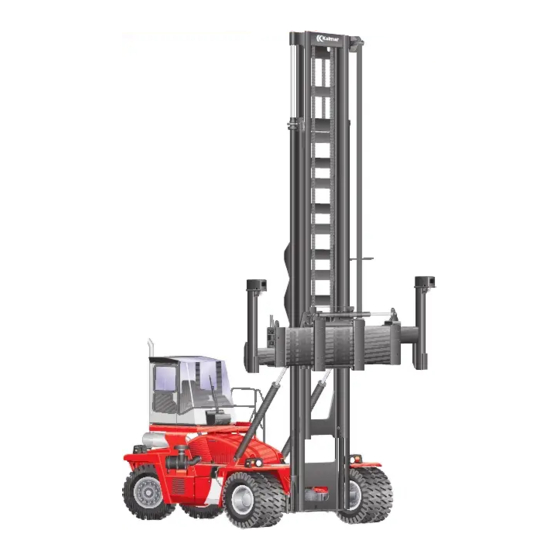
Complete machine, description page – Kalmar DCF90-100 is a forklift truck for handling empty containers. The machine has a lift capacity of up to 9 – 10 metric tons depending on version. The power source is a straight 6-cylinder, 4-stroke turbocharged low- emission diesel engine with unit injectors and air-to-air intercooler. -
Page 40: Troubleshooting, General Work Instructions
In some cases, there is information on what con- ditions are required in order for it to be possible to activate the function. Measurement points are marked with flags (C as in checkpoint for measuring outlet, D for diagnostic menu). Workshop Manual DCF 90-100 VDCF03.01GB... -
Page 41: Troubleshooting Without An Error Code, Example
5 Use the function group to find more information if needed. In section 0–12 there is function description, the function's includ- ed components and their position as well as, in certain cases, work instructions for how components are checked, cleaned or adjusted. Workshop Manual DCF 90-100 VDCF03.01GB... - Page 42 K8:5 - S107, brake control switch, indicates re- released. unit and the compo- K8:13 - S107 leased and applied nent with diagnostic at same time or menu. nothing at all. Check component. Workshop Manual DCF 90-100 VDCF03.01GB...
-
Page 43: Troubleshooting Cable Harness
Unplug the connector at both the control unit and the compo- nent in question. Measure the resistance of one lead at a time. Measure be- tween the lead and a frame-connected part of the machine. The multimeter should show endless resistance. Workshop Manual DCF 90-100 VDCF03.01GB... -
Page 44: Troubleshooting Hydraulic Hoses
4 Inspect the entire hose and splicing points with respect to chafing damage, pinching damage and leaks. Change damaged hoses. When removing a hydraulic hose, change of O-ring is always recommended on the hoses that have these (ORFS). Workshop Manual DCF 90-100 VDCF03.01GB... - Page 45 NO (normally open) switch, coolant level ..........37 1.7.10 Engine heater ..................37 Control system engine ................38 1.9.1 Control unit, engine ................38 1.11 Start/stop ....................39 1.11.1 Starter motor ..................39 1.11.2 Stopping device ................... 39 Workshop Manual DCF 90-100 VDCF03.01GB...
- Page 46 1 Engine Workshop Manual DCF 90-100 VDCF03.01GB...
-
Page 47: Mm Mm Mm Mm Mm Mm
References to component supplier documentation are only provided in exceptional cases. If information about a component is not found, the component supplier documentation should be used. Workshop Manual DCF 90-100 VDCF03.01GB... - Page 48 CAN bus. If the tem, error shown with er- 11.5.3.11 Control unit KIT (D790-2) key is turned to the preheating posi- ror code. tion, then preheating is also sent on the CAN bus. Workshop Manual DCF 90-100 VDCF03.01GB...
- Page 49 The NO switch for coolant level U = 24 V NO (normally open) switch, coolant level page (B759) sends a voltage signal to the engine unit (D794) if the coolant lev- el in the expansion tank is low. Workshop Manual DCF 90-100 VDCF03.01GB...
- Page 50 11.5.3.1 Cab control unit (D790-1) speed limitation, the cab control unit ror code. (D790-1) transmits a reduce engine rpm request on the CAN bus. Control unit engine (D794) restricts Se Engine control unit, general page 38 engine rpm. Workshop Manual DCF 90-100 VDCF03.01GB...
- Page 51 Turbo Fuel filter Filling point engine oil Solenoid valve proportional valve high-pressure fuel (MPROP) Connection cab heat Electrical connection, engine control unit (D794) Alternator Sensor camshaft rpm Fuel pump Oil plug Sensor fuel pressure (rail) Workshop Manual DCF 90-100 VDCF03.01GB...
- Page 52 1 Engine – 1 Engine Volvo TAD760VE, right side (in machine’s direction of travel) Oil plug Sensor crankshaft rpm Starter motor (M654) Thermostat housing Drain point coolant Workshop Manual DCF 90-100 VDCF03.01GB...
- Page 53 2 Attach hoisting equipment to the engine. 3 Disconnect required hoses and cables before separating engine and transmission. NOTE Drain and collect liquids before detaching hoses. 4 Remove the radiator. 5 Use a jack to secure the gearbox. Workshop Manual DCF 90-100 VDCF03.01GB...
- Page 54 11 Withdraw the engine rearwards to separate it from the gearbox. NOTE Beware of balance before the engine is lifted. NOTE If the flex plates are damaged during engine replacement, they must be replaced. 12 Lift the engine away. Workshop Manual DCF 90-100 VDCF03.01GB...
- Page 55 15 Transfer the engine brackets to the new engine; tighten to 169 Nm (oiled screw). 16 Centre a stud on the flywheel so that it aligns with the hole in the flywheel housing. Workshop Manual DCF 90-100 VDCF03.01GB...
- Page 56 Turn the engine for each nut to be installed to the flex plate. 20 Tighten the screws which fix the gearbox and engine. Tighten the gearbox to the gearbox mountings. Refit the cover plate and pro- peller shaft. Workshop Manual DCF 90-100 VDCF03.01GB...
- Page 57 25 Remove the jack from underneath the gearbox. 26 Connect the required hoses and cables for the engine and trans- mission. Check and fill fluids as needed. 27 Bleed air from the engine’s fuel system before start. Workshop Manual DCF 90-100 VDCF03.01GB...
- Page 58 CAN bus. If the tem, error shown with er- 11.5.3.11 Control unit KIT (D790-2) key is turned to the preheating posi- ror code. tion, then preheating is also sent on the CAN bus. Workshop Manual DCF 90-100 VDCF03.01GB...
- Page 59 The NO switch for coolant level U = 24 V NO (normally open) switch, coolant level page (B759) sends a voltage signal to the engine unit (D794) if the coolant lev- el in the expansion tank is low. Workshop Manual DCF 90-100 VDCF03.01GB...
- Page 60 11.5.3.1 Cab control unit (D790-1) speed limitation, the cab control unit ror code. (D790-1) transmits a reduce engine rpm request on the CAN bus. Control unit engine (D794) restricts Se Engine control unit, general page 38 engine rpm. Workshop Manual DCF 90-100 VDCF03.01GB...
- Page 61 Cummins QSB 6.7, left side (in machine’s direction of travel) Hole for flex plate Coolant inlet Flywheel Oil cooler Crankcase ventilation Oil filter Injector drainage Turbo inlet Lifting eye Turbo wastegate Oil filling Exhaust manifold Coolant outlet Starter motor Alternator Flywheel housing Workshop Manual DCF 90-100 VDCF03.01GB...
- Page 62 Fuel rail Fan drive Pressure reducing valve in rail Air inlet Fuel filter Coolant temperature sensor Dipstick Turbo air inlet Electronic control unit (D794) Turbo air outlet Crankshaft speed sensor High-pressure fuel lines Vibration damper (rubber) Workshop Manual DCF 90-100 VDCF03.01GB...
- Page 63 Drain and collect liquids before detaching hoses. 4 Remove the radiator. 5 Use a jack to secure the gearbox. 6 Remove the screws holding the cover plate to the flywheel on the left side of the engine. Workshop Manual DCF 90-100 VDCF03.01GB...
- Page 64 13 Lift the engine away. Assembly 14 Transfer the engine brackets to the new engine; tighten to 330 Nm (oiled screw). 15 Apply lubricating grease to the converter connection - both on the engine and the gearbox. Workshop Manual DCF 90-100 VDCF03.01GB...
- Page 65 Secure the bolt in the socket when installing. 21 Fit the screws that fasten the gearbox and engine and tighten them to 52 Nm (oiled screw). Workshop Manual DCF 90-100 VDCF03.01GB...
- Page 66 25 Remove the hoisting equipment from the engine. 26 Remove the jack from underneath the gearbox. 27 Connect the required hoses and cables for the engine and trans- mission. Check and fill fluids as needed. Workshop Manual DCF 90-100 VDCF03.01GB...
-
Page 67: Controls And Instruments
Conditions for starter motor engagement are that transmis- sion is in neutral position and the engine is not already run- ning. The signal can be checked from the diagnostic menu, see section 8 Control system, group 8.4.6.4 ENGINE, menu 4. Workshop Manual DCF 90-100 VDCF03.01GB... -
Page 68: Accelerator Pedal
7 Calibrate the gas pedal, see the section 8 Control system, group 8.5.2.3 Calibrate DRIVE-TRAIN. 1. Accelerator pedal 2. Brake pedal Accelerator pedal, calibration page – See section 8 Control system, group 8.5.2.3 Calibrate DRIVE-TRAIN. Workshop Manual DCF 90-100 VDCF03.01GB... -
Page 69: Fuel System
– The signal can be checked from the diagnostic menu, see section 8 Control system, group 8.4.3.7 CAB, menu 7. 1. Fuel filling point 2. Fuel tank 3. Fuel level sensor (behind air filter) Workshop Manual DCF 90-100 VDCF03.01GB... -
Page 70: Air Intake And Exhaust Outlet
WARNING Hot exhaust system! Risk of burn injuries! Never touch the turbo or muffler when the machine is running or just after it has been turned off! 1. End pipe 2. Silencer 3. Exhaust pipe Workshop Manual DCF 90-100 VDCF03.01GB... -
Page 71: Intercooler
The charge-air is cooled by an air-air intercooler in the upper part of the cooler unit. Also refer to Cooling system, description page 28. Radiator core 1. Transmission oil cooler 2. Fuel cooler 3. Radiator engine 4. Intercooler 5. Expansion tank 6. Attachment condenser (to AC) Workshop Manual DCF 90-100 VDCF03.01GB... -
Page 72: Cooling System
When the coolant is warmer than the thermostat opening temper- ature it is pumped through the radiator and then back to the cool- ant pump. The expansion tank allows the coolant to expand without escap- ing from the engine. Workshop Manual DCF 90-100 VDCF03.01GB... -
Page 73: Radiator And Expansion Tank
Also refer to Cooling system, description page 28. For more information, see supplier documentation, engine. Radiator core 1. Transmission oil cooler 2. Fuel cooler 3. Radiator engine 4. Intercooler 5. Expansion tank 6. Attachment condenser (to AC) Workshop Manual DCF 90-100 VDCF03.01GB... -
Page 74: Cooling Fan
3 Remove the belt from the coolant pump first. 4 Install the new belt. Let back the belt tensioner and check that the belt is positioned correctly in the grooves, and that it is tensioned correctly. 1. Coolant pump Workshop Manual DCF 90-100 VDCF03.01GB... -
Page 75: Coolant
NOTE Read the safety instructions before starting work with the cooling system, see section B Safety. NOTE Before draining, stop the engine and remove the filler cap. Workshop Manual DCF 90-100 VDCF03.01GB... - Page 76 NOTE Only use cleaning agents approved by the engine manufac- turer. Carefully follow the instructions on the package. Filler orifice 10 When the cooling system is completely free from impurities, close the drain valves. Workshop Manual DCF 90-100 VDCF03.01GB...
- Page 77 Open all heat controls on the heater so that it is bled free from air. 13 Stop the engine after approx. one hour and check the coolant lev- el, top up if needed. Workshop Manual DCF 90-100 VDCF03.01GB...
- Page 78 The system must be filled well to prevent air pocket formation. During filling, air must be vented out from the cooling channels. Wait 2 to 3 minutes to vent the system and then fill it. Workshop Manual DCF 90-100 VDCF03.01GB...
- Page 79 It is very important that the correct concentration and volume of coolant is filled in the system. Mix in a sep- arate clean container prior to filling the cooling sys- tem. Be sure that the fluids mix well. Workshop Manual DCF 90-100 VDCF03.01GB...
- Page 80 It is very important that the correct concentration and volume of coolant is filled in the system. Mix in a sen- parate clean container prior to filling the cooling sys- tem. Be sure that the fluids mix well. Workshop Manual DCF 90-100 VDCF03.01GB...
-
Page 81: Normally Open) Switch, Coolant Level
1.7.10 Engine heater Engine heater, description page – See supplier documentation engine. A start-inhibitor function is available as an option coupled with the en- gine heater. The function is activated when the heater is running. Workshop Manual DCF 90-100 VDCF03.01GB... -
Page 82: Control System Engine
1 Engine – 1.9 Control system engine Control system engine 1.9.1 Control unit, engine Engine control unit, general page – See section 11 Common electrics, group 11.5.3.10 Engine control unit and supplier documentation, engine. Workshop Manual DCF 90-100 VDCF03.01GB... -
Page 83: Start/Stop
Automatic engine shutdown is available as an option. This means that the engine shuts off automatically after 3-10 minutes (depending on customer setting) if the machine is idling without the operator in the seat. Workshop Manual DCF 90-100 VDCF03.01GB... - Page 84 1 Engine – 1.11.2 Stopping device Workshop Manual DCF 90-100 VDCF03.01GB...
- Page 85 Oil filter ....................26 Cooling system ..................27 2.7.3 Oil cooler ....................27 Transmission control system ..............28 2.8.1 Control unit transmission ..............28 2.8.2 Normally closed (NC) switch, disengagement ........28 2.8.3 Transmission cable harness ..............29 Workshop Manual DCF 90-100 VDCF03.01GB...
- Page 86 2 Transmission Workshop Manual DCF 90-100 VDCF03.01GB...
-
Page 87: Mm Mm Mm Mm Mm Mm
References to component supplier documentation are only provided in exceptional cases. If information about a component is not found, the component supplier documentation should be used. Workshop Manual DCF 90-100 VDCF03.01GB... - Page 88 11.5.3.11 Control unit KIT (D790-2) (forward or reverse) on the CAN bus. ror code. The transmission’s oil pump pumps oil when the engine is running. The transmission’s oil filter cleans the oil from impurities. Workshop Manual DCF 90-100 VDCF03.01GB...
- Page 89 D14: Diagnostic menu, see section 8 Control (B758) sends the transmission con- transmission, error system , group 8.4.7.6 TRANSM, menu 6 trol unit (D793) a pulse signal with shown with error code. frequency proportional to output shaft speed. Workshop Manual DCF 90-100 VDCF03.01GB...
- Page 90 , group 8.4.7.1 TRANSM, menu 1 Conn 2, U = 24 V allow drive disengagement. Brake pressure below 0.2 MPa: Conn 1, U = 24 V Conn 2, U = 0 V Workshop Manual DCF 90-100 VDCF03.01GB...
- Page 91 Transmission control unit, general page 28 supplies voltage to valve block trans- transmission, error mission control so that the drive is shown with error code. put in neutral three seconds after the operator leaves the driver’s seat. Workshop Manual DCF 90-100 VDCF03.01GB...
- Page 92 Diagnostic menu, see section 8 Control trols Pressure booster drive forward. system , group 8.4.7.8 TRANSM, menu 8 and 8.4.7.9 TRANSM, menu 9 Pressure booster forward increases the 0-2000 kPa pressure and pressurizes Drive clutch for- ward. Workshop Manual DCF 90-100 VDCF03.01GB...
- Page 93 Drive clutch 3rd gear locks transmission in 0-2000 kPa 3rd gear when the clutch is pressurized. The safety valve leads the oil back to the Opening pressure: 850 sump if the pressure to the torque converter becomes too high. Workshop Manual DCF 90-100 VDCF03.01GB...
- Page 94 The transmission oil cooler cools the oil. The bypass valve torque converter leads Opening pressure: 400 the oil past the torque converter if the pres- sure becomes too high. The oil is distributed to different lubrication points in the transmission. Workshop Manual DCF 90-100 VDCF03.01GB...
- Page 95 Radiator connection (from radiator to sump) Thermostat Temperature monitor torque converter (S221) Breather filter transmission Turbine speed sensor (B751) Sensor, drum rpm (B752) Sensor rpm output shaft (B758) Engine speed and oil temperature sensor (B758/766) Output shaft Sensor oil pressure Workshop Manual DCF 90-100 VDCF03.01GB...
- Page 96 Control unit KIT (D790-2) Control unit, Volvo engine (D794) Control unit KID (D795) Control unit, Cummins engine (D794) Control unit cab (D790-1) Frame control unit (D797-1) Sensor operator in seat (S230) Switch (NC), disengagement (S220-2) Workshop Manual DCF 90-100 VDCF03.01GB...
- Page 97 1 Machine in service position, see section B Safety. 2 Remove the propeller shaft from the transmission. 3 Detach relevant hoses and cables before separating the engine and gearbox. NOTE Drain and collect liquids before detaching hoses. Workshop Manual DCF 90-100 VDCF03.01GB...
- Page 98 7 Support the engine from underneath with a jack NOTE Secure the engine so that it does not tip over when the gearbox is removed. 8 Remove the screws holding the gearbox to the gearbox mount- ing. Workshop Manual DCF 90-100 VDCF03.01GB...
- Page 99 NOTE If the flex plates are damaged during gearbox replacement, they must be replaced. 11 Remove the gearbox. Assembly 12 Apply lubricating grease to the converter connection - both on the engine and the gearbox. Workshop Manual DCF 90-100 VDCF03.01GB...
- Page 100 17 Install the screws which fix the gearbox and engine, but do not tighten the screws fully. Leave about a millimetre between the en- gine and gearbox to facilitate installation of the nuts for the flex plate/flywheel. Workshop Manual DCF 90-100 VDCF03.01GB...
- Page 101 22 Remove the hoisting equipment from the gearbox. 23 Remove the jack from underneath the engine. 24 Attach relevant hoses and cables to the engine. Check fluid lev- els and top up as necessary. 25 Calibrate the transmission; see Transmission, calibration page Workshop Manual DCF 90-100 VDCF03.01GB...
-
Page 102: Controls And Instruments
The switch is supplied voltage by and sends signals to the KIT control unit (D790-2). The signal can be checked from the diagnostic menu, see section 8 Control system , group 8.4.7.2 TRANSM, menu 2. Workshop Manual DCF 90-100 VDCF03.01GB... -
Page 103: Torque Converter/Clutch System
1 Machine in service position, see section B Safety. 2 Remove the gearbox; see Gearbox, replacement page 13. 3 Remove the bolts holding the flex plate to the transmission. Fastening the flex plate (TE17312 gearbox with Volvo TAD760VE engine) Workshop Manual DCF 90-100 VDCF03.01GB... - Page 104 5 Reinstall the gearbox; see Gearbox, replacement page 13. 6 Before the machine is put into operation, the transmission must be calibrated; see Transmission, calibration page 28. Fastening the flex plate (other gearbox and engine al- ternatives) Workshop Manual DCF 90-100 VDCF03.01GB...
-
Page 105: Lubrication System
4 If the oil filter must be changed, see Transmission oil filter, chang- ing page 26. 5 When the transmission oil has drained, fit the drain plug. Make sure that the washer for the oil plug is included. Draining transmission oil Workshop Manual DCF 90-100 VDCF03.01GB... - Page 106 11 Allow the engine to idle. Check the transmission oil level (see Transmission oil level check page 23) and top up to the max. oil level mark. Operating menu oil temperature a. Transmission oil temperature b. Hydraulic oil temperature Workshop Manual DCF 90-100 VDCF03.01GB...
- Page 107 Work carefully when filling transmission oil to prevent other fluids or particles from contaminating the oil, which means risk of transmission damage. A. Position of oil filling point and level check B. Oil filling point and oil dipstick Workshop Manual DCF 90-100 VDCF03.01GB...
-
Page 108: Oil Cooler
This means that the oil reaches normal working temperature more quickly. For more detailed information, see supplier documentation, transmis- sion. Radiator core 1. Transmission oil cooler 2. Fuel cooler 3. Radiator engine 4. Intercooler 5. Expansion tank 6. Attachment condenser (to AC) Workshop Manual DCF 90-100 VDCF03.01GB... - Page 109 6 Fill with transmission oil; see Transmission oil, changing page 21. 7 Start the engine and check for leaks. 8 Check the transmission oil level; see Transmission oil level check page 23. Workshop Manual DCF 90-100 VDCF03.01GB...
-
Page 110: Oil Filter
If the transmission oil is to be changed - change the trans- mission oil before starting the engine. 6 Check for leaks at the transmission oil filter. Oil filter transmission 7 Check the transmission oil level, see Transmission oil level check page 23. Workshop Manual DCF 90-100 VDCF03.01GB... -
Page 111: Cooling System
2 Transmission – 2.7 Cooling system Cooling system 2.7.3 Oil cooler Oil cooler, description page – See Oil cooler, description page 24. Workshop Manual DCF 90-100 VDCF03.01GB... -
Page 112: Transmission Control System
5. Brake cylinder connection, to wheel brake 6. Brake pressure connection, from brake valve 7. Switch (NC), declutch (S220) 8. NO switch, brake lights (S216) 9. Measurement connection, brake pressure 10. Measuring outlet, brake cooling back pressure Workshop Manual DCF 90-100 VDCF03.01GB... -
Page 113: Transmission Cable Harness
2 Transmission – 2.8.3 Transmission cable harness 2.8.3 Transmission cable harness Transmission cable harness, description page – See section E Schematics. Workshop Manual DCF 90-100 VDCF03.01GB... - Page 114 2 Transmission – 2.8.3 Transmission cable harness Workshop Manual DCF 90-100 VDCF03.01GB...
- Page 115 3 Driveline/Axle 3 Driveline/Axle Table of Contents 3 Driveline/Axle mm mm mm mm mm mm Driveline/axle ....................3 Propeller shaft .................... 3 Drive axle ....................4 Workshop Manual DCF 90-100 VDCF03.01Gb...
- Page 116 3 Driveline/Axle Workshop Manual DCF 90-100 VDCF03.01Gb...
- Page 117 2 Clean the contact surfaces (cross-toothed) on the drive axle and gearbox. 3 Fit the propeller shaft in position with the coupling upward. 4 Fit the propeller shaft attaching bolts. Tightening torque 98 Nm (oiled screw). Retighten the attaching bolts after 50 hours of operation. Workshop Manual DCF 90-100 VDCF03.01Gb...
- Page 118 2 Park the machine with blocks behind the steering wheels. 3 Depressurize the hydraulic systems, See section B Safety. 4 Turn the start key to position 0 and turn off the main electric pow- Workshop Manual DCF 90-100 VDCF03.01Gb...
- Page 119 NOTE Plug all unions at once to protect the hydraulic system from contamination. 1. Hydraulic hoses 2. Cables 7 Remove the casing (position 3) on the parking brake. 3. Casing parking brake Workshop Manual DCF 90-100 VDCF03.01Gb...
- Page 120 13 Block up the drive axle under the hubs. CAUTION The drive axle may start to roll. Crushing injury! Make sure that the drive axle does not roll away when not under control. Lifting machine Workshop Manual DCF 90-100 VDCF03.01Gb...
- Page 121 Attaching bolts drive axle 16 Undo the hydraulic hoses on the drive axle. NOTE Plug all unions at once to protect the hydraulic system from contamination. 17 Transfer the couplings from the old axle to the new axle. Workshop Manual DCF 90-100 VDCF03.01Gb...
- Page 122 23 Lift the drive axle into place under the frame. CAUTION The drive axle may start to roll. Crushing injury! Make sure that the drive axle does not roll away when not under control. 24 Lower the frame towards the drive axle. Workshop Manual DCF 90-100 VDCF03.01Gb...
- Page 123 30 Connect the propeller shaft to the drive axle; see Propeller shaft, replacement page 3. 31 Check the oil level in the drive axle. 32 Start the machine and bleed the brakes, see section 4 Brakes, group 4.3.9 Wheel brake. 33 Check for leaks. Workshop Manual DCF 90-100 VDCF03.01Gb...
- Page 124 3 Driveline/Axle – 3.3 Drive axle Workshop Manual DCF 90-100 VDCF03.01Gb...
- Page 125 Cooling fan ................... 39 4.8.10 Sensor hydraulic oil temperature ............39 4.8.11 Breather filter hydraulic oil tank ............39 4.8.12 Oil filter ....................39 4.8.13 Pipes and hoses .................. 39 4.8.14 Hydraulic oil ..................40 Workshop Manual DCF 90-100 VDCF03.01GB...
- Page 126 4 Brakes Workshop Manual DCF 90-100 VDCF03.01GB...
-
Page 127: Mm Mm Mm Mm Mm Mm
5 Check that the rubber pad on the brake pedal is intact and that the pattern is not worn away. Replace as necessary. 6 Check the brake valve; see Brake valve, checking page 20. Lubrication points, brake pedal. (The illustration shows a loose brake pedal). Workshop Manual DCF 90-100 VDCF03.01GB... - Page 128 Fit the pedal and fit the pedal’s attaching bolts. 11 Connect the steering valve to the brake pedal. 12 Connect the brake valve to the brake pedal. 13 Fit the clutch pedal to the brake pedal. Workshop Manual DCF 90-100 VDCF03.01GB...
- Page 129 14 Close the drain valve on the accumulator charging valve. NOTE Check that the accumulator drain valve is fully closed and tighten the lock ring. 15 Grease and adjust the brake pedal, see Brake pedal, checking and adjusting page 3. Workshop Manual DCF 90-100 VDCF03.01GB...
-
Page 130: Power-Assisted Brake System
The brake cylinders compress the See pressure plate on left Wheel brake, description page 27 discs in the brake unit. frame beam. Workshop Manual DCF 90-100 VDCF03.01GB... - Page 131 Controlled by control system, Section 11 Common electrics , group Warning light brake pressure. error shown with error code. 11.5.3.11 KIT control unit (D790-2) Hydraulic diagram, see section E Schematics group 10 Common hy- draulics, Basic machine Workshop Manual DCF 90-100 VDCF03.01GB...
- Page 132 NC switch, brake pressure (S204) Control unit KIT (D790-2) Distribution block drive axle Brake valve NO switch, brake lights (S216) Frame control unit (D797-1) Oil filter Wheel brake Hydraulic oil pump Accumulator charging valve Accumulators Workshop Manual DCF 90-100 VDCF03.01GB...
-
Page 133: Hydraulic Oil Pump
3 Depressurize the hydraulic systems, See section B Safety. 4 Connect a pressure gauge (0–25 MPa) to the pump pressure measuring outlet on the accumulator charging valve. 5 Start the engine and run it at idling speed. Measuring outlet, pump pressure Workshop Manual DCF 90-100 VDCF03.01GB... - Page 134 12 Depressurize the hydraulic systems, See section B Safety. 13 Connect a pressure gauge (0–25 MPa) to the measuring outlet for accumulator pressure on the accumulator charging valve. 14 Start the engine and run it at idling speed. Measuring outlet, accumulator pressure Workshop Manual DCF 90-100 VDCF03.01GB...
-
Page 135: Oil Filter
See the section 10 Common hydraulics, group 10.4.1 Gear pump with fixed displace- ment. 4.3.2 Oil filter Hydraulic oil filter, general page – See Hydraulic oil filter, description page 39. Workshop Manual DCF 90-100 VDCF03.01GB... -
Page 136: Accumulator Charging Valve
7. NC switch, parking brake (GHB) (S260) 8. Connection, accumulators (ACC) 9. NC switch, brake pressure (LB) (S204) 10. Connection, parking brake calliper (HB) 11. Drain valve 12. Main valve charging 13. Pressure limiting valve Workshop Manual DCF 90-100 VDCF03.01GB... - Page 137 Close the valves and check the max. pressure again. 5 Repeat steps 3 and 4 until the pressure is correct. Adjusting screw accumulator charging pressure Workshop Manual DCF 90-100 VDCF03.01GB...
- Page 138 13 Turn on the main electric power and start the engine. Check that the hydraulic connections are sealed tightly. 14 Check the charging and changing function, see Accumulator charging, checking and adjustment page 13. Workshop Manual DCF 90-100 VDCF03.01GB...
-
Page 139: Accumulator
Safety. NOTE A special tool for checking the accumulators can be ordered from Kalmar Industries. The procedure without use of the special tool is described below. 1 Machine in service position, see section B Safety. 2 Depressurize the hydraulic systems, See section B Safety. - Page 140 NOTE Check that the accumulator drain valve is fully closed and tighten the lock ring. 10 Check that the plug seals properly. 11 Stop the engine Workshop Manual DCF 90-100 VDCF03.01GB...
- Page 141 I. 22 Check that at least 8 brake applications (pedal depressions) can be performed before the pressure drops to 10 MPa. At 11.5 MPa the warning lamp for low brake pressure must come Workshop Manual DCF 90-100 VDCF03.01GB...
- Page 142 9 Close the drain valve on the accumulator charging valve. 10 Turn on the main electric power and start the engine. 11 Check that the accumulator's connection is sealed tightly. 12 Check precharging and function, see Accumulator, checking page 15 steps 18-19. Workshop Manual DCF 90-100 VDCF03.01GB...
-
Page 143: Brake Valve
This provides optimum pedal responsiveness and in- creased safety as the operator senses if no brake pressure is being built up (no resistance in the pedal). 1. Inlet from accumulators [P] 2. Return connection [T] 3. Outlet to brake cylinders [B] Workshop Manual DCF 90-100 VDCF03.01GB... - Page 144 12 Remove the pressure gauge and fit the protective cap on the measuring outlet. 13 Close the drain valve on the accumulator charging valve. NOTE Check that the accumulator drain valve is fully closed and tighten the lock ring. Workshop Manual DCF 90-100 VDCF03.01GB...
- Page 145 9 Connect the hydraulic hoses to the brake valve in accordance with the marking. NOTE Check that the O-rings are intact and are fitted correctly. 10 Grease and adjust the brake pedal, see Brake pedal, checking and adjusting page 3. Workshop Manual DCF 90-100 VDCF03.01GB...
- Page 146 13 Test the brakes a couple of times. 14 Check that the brake valve's connections are sealed tightly. 15 Bleed the wheel brakes' brake cylinders, see Wheel brakes, bleeding page 28. Workshop Manual DCF 90-100 VDCF03.01GB...
-
Page 147: Drive Axle Block
5. Brake cylinder connection, to wheel brake 6. Brake pressure connection, from brake valve 7. NO switch, declutch (S220) 8. NO switch, brake lights (S216) 9. Measurement connection, brake pressure 10. Measuring outlet, brake cooling back pressure Workshop Manual DCF 90-100 VDCF03.01GB... -
Page 148: Brake Pressure Nc (Normally Closed) Switch
7 Stop the engine and turn the starter key to position I. 8 Brake several times, stop when the warning lamp for low brake pressure comes on. 9 Read off the accumulator pressure. The pressure should be ap- prox. 11.5 MPa. Workshop Manual DCF 90-100 VDCF03.01GB... -
Page 149: Normally Open) Switch, Brake Lights
50 °C. 2 Stop the engine and turn the starter key to position I. 3 Brake and check that the brake light comes on. 4 Depressurize the hydraulic systems, See section B Safety. Workshop Manual DCF 90-100 VDCF03.01GB... - Page 150 12 Remove the pressure gauge and fit the protective cap on the measuring outlet. 13 Close the drain valve on the accumulator charging valve. NOTE Check that the accumulator drain valve is fully closed and tighten the lock ring. Workshop Manual DCF 90-100 VDCF03.01GB...
-
Page 151: Wheel Brake
The wheel brakes have two main sections - disc assembly and brake cylinder. The disc assembly performs the braking. The brake cylinder presses the discs in the disc assembly together during braking. Wheel hub and brake, cross section 1. Disc assembly 2. Brake cylinder Workshop Manual DCF 90-100 VDCF03.01GB... - Page 152 6 Move the spanner and hose and repeat steps 1–4 on the other side. 7 Check the oil level in the brake system, fill as necessary. Wheel brake, replacement page – See supplier documentation, drive axle. Workshop Manual DCF 90-100 VDCF03.01GB...
-
Page 153: Pipes And Hoses
The pressure moves the metal ring sideways and compresses the disc assembly. Brake cylinder 4.3.10 Pipes and hoses Piped and hoses, description page – See section 10 Common hydraulics, group 10.5.1 Pipes and hoses. Workshop Manual DCF 90-100 VDCF03.01GB... -
Page 154: Parking Brake System
, group 8.4.5.5 HYD, menu 5 Switch in resting position: Both signals must be correct to enable re- Conn. 1, U = 0 V lease of the parking brake. Conn. 7, U = 24 V Workshop Manual DCF 90-100 VDCF03.01GB... - Page 155 Section 9 Frame, body, cab and accesso- the parking brake indicator light (508). tem, error shown with er- ries , group 9.1 Controls and instruments ror code. Hydraulic diagram, see section E Schematics, group 10 Common hy- draulics, Basic machine Workshop Manual DCF 90-100 VDCF03.01GB...
- Page 156 Switch (NO), parking brake (S200) Control unit KIT (D790-2) Parking brake disc Switch parking brake (S107) Parking brake caliper Frame control unit (D797-1) Oil filter Accumulator charging valve Hydraulic oil pump Solenoid valve parking brake (Y642) Accumulators Workshop Manual DCF 90-100 VDCF03.01GB...
-
Page 157: Hydraulic Oil Pump
The brake caliper should be able to move. 4 Activate the parking brake with the parking brake switch and check that the parking brake’s brake caliper is applied. Workshop Manual DCF 90-100 VDCF03.01GB... -
Page 158: Parking Brake Unit
2 Turn off the engine and turn the start key to position I. 3 Release the parking brake. 4 Check that the parking brake caliper can move on the bracket. 5 Check that the brake disc is free from oil and dirt. Workshop Manual DCF 90-100 VDCF03.01GB... - Page 159 This means that the parking brake is applied if the brake system loses pressure. This, in turn, means that the machine is braked if a serious fault arises. 1. Brake pads 2. Release cylinder 3. Application spring 4. Release screw 5. Adjusting washer Workshop Manual DCF 90-100 VDCF03.01GB...
- Page 160 3 Undo the lock nut. 4 Slacken the adjusting screw to release the brake pads. 5 Remove the split pin and undo the nut on one of the attaching bolts holding the parking brake calliper in place. Workshop Manual DCF 90-100 VDCF03.01GB...
-
Page 161: Parking Brake Nc Switch
Control system , group 8.4.5.5 HYD, menu 5. NOTE Gears cannot be engaged when the parking brake is applied. 4.5.6 Pipes and hoses Piped and hoses, description page – See section 10 Common hydraulics, group 10.5.1 Pipes and hoses. Workshop Manual DCF 90-100 VDCF03.01GB... -
Page 162: Temperature Control, Cleaning And Hydraulic Oil
See Power-assisted brake system, component positions page 8. 4.8.1 Hydraulic oil tank Hydraulic oil tank, description page – See section 10 Common hydraulics , group 10.3.1 Hydraulic oil tank. Workshop Manual DCF 90-100 VDCF03.01GB... -
Page 163: Hydraulic Oil Pump
Hydraulic oil filter, description page – See section 10 Common hydraulics , group 10.6.7 Hydraulic oil filter. 4.8.13 Pipes and hoses Piped and hoses, description page – See section 10 Common hydraulics, group 10.5.1 Pipes and hoses. Workshop Manual DCF 90-100 VDCF03.01GB... -
Page 164: Hydraulic Oil
4 Brakes – 4.8.14 Hydraulic oil 4.8.14 Hydraulic oil Hydraulic oil, description page – See section 10 Common hydraulics , group 10.6.8 Hydraulic oil. Workshop Manual DCF 90-100 VDCF03.01GB... - Page 165 Steering cylinder .................. 10 5.2.5 Steering axle cradle ................12 5.2.6 Link arm ....................12 5.2.7 Wheel spindle ..................12 5.2.8 Wheel hub .................... 12 5.2.9 Shuttle valve ..................13 5.2.13 Pipes and hoses .................. 13 Workshop Manual DCF 90-100 VDCF03.01GB...
- Page 166 5 Steering Workshop Manual DCF 90-100 VDCF03.01GB...
-
Page 167: Mm Mm Mm Mm Mm Mm
The steering wheel is turned and acts on Section 9 Frame, body, cab and accesso- the steering valve's input shaft. ries, group 9.1 Controls and instruments Workshop Manual DCF 90-100 VDCF03.01GB... - Page 168 Basic machine Power-assisted steering system, component page – positions Hydraulic components Hydraulic oil pump for steering and load handling Connection terminal, return oil Shuttle valve Steering valve Priority valve Steering axle with steering cylinder Workshop Manual DCF 90-100 VDCF03.01GB...
-
Page 169: Hydraulic Oil Pump
Compare this to the steering pressure on the hydraulics plate. 6 Turn the start key to position 0 and turn off the main electric pow- 7 Remove the pressure gauge and fit the protective cap on the measuring outlet. Workshop Manual DCF 90-100 VDCF03.01GB... -
Page 170: Priority Valve
Read the safety instructions for oil before working, see section B Safety. 1 Machine in service position, see section B Safety. 2 Depressurise the hydraulic system, see section B Safety. 3 Turn the start key to position 0 and turn off the main electric power. Workshop Manual DCF 90-100 VDCF03.01GB... - Page 171 13 Tighten the hydraulic connection between priority valve and col- lection block. 14 Start the engine and check that the hydraulic connections at the priority valve are sealed. 15 Check steering pressure; see Steering pressure, checking page Workshop Manual DCF 90-100 VDCF03.01GB...
-
Page 172: Steering Valve
1 Stop the engine and turn the starter key to position I. 2 Depressurize the hydraulic systems, See section B Safety. 3 Turn the start key to position 0 and turn off the main electric power. 1. Water valve 2. Steering valve Workshop Manual DCF 90-100 VDCF03.01GB... - Page 173 10 Turn on the main electric power and start the engine. 11 Check that the connections on the steering valve are sealed. 12 Steer very carefully a few times right - left, to bleed the steering valve and steering cylinder. Workshop Manual DCF 90-100 VDCF03.01GB...
-
Page 174: Steering Cylinder
1 Park the machine with the wheels fully turned so that the steering cylinder can be lifted out to one side. 2 Machine in service position, see section B Safety. 3 Depressurise the brake and hydraulic systems, see section B Safety. Workshop Manual DCF 90-100 VDCF03.01GB... - Page 175 9 Lubricate and fit the steering cylinder attaching bolts. Tighten them crosswise in steps until 680 Nm is reached. 10 Transfer parts to the new steering cylinder. NOTE Check that the O-rings are intact and fitted correctly. Attaching bolts steering cylinder. Workshop Manual DCF 90-100 VDCF03.01GB...
-
Page 176: Steering Axle Cradle
Wheel spindle Wheel spindle, general page – See section 6 Wheel suspension , group 6.2.2 Wheel spindle. 5.2.8 Wheel hub Wheel hub, general page – See section 6 Wheel suspension , group 6.2.3 Wheel hub. Workshop Manual DCF 90-100 VDCF03.01GB... -
Page 177: Shuttle Valve
Shuttle valve, description page – See section 10 Common hydraulics , group 10.5.3 Shuttle valve. 5.2.13 Pipes and hoses Piped and hoses, description page – See section 10 Common hydraulics, group 10.5.1 Pipes and hoses. Workshop Manual DCF 90-100 VDCF03.01GB... - Page 178 5 Steering – 5.2.13 Pipes and hoses Workshop Manual DCF 90-100 VDCF03.01GB...
- Page 179 Steering axle cradle ................4 6.2.2 Wheel spindle ..................6 6.2.3 Wheel hub ....................8 Tyre and rim system ................. 13 6.3.1 Tyres ....................15 6.3.2 Rims ..................... 16 6.3.3 Nut, washer and clamp ................ 17 Workshop Manual DCF 90-100 VDCF03.01GB...
- Page 180 6 Suspension Workshop Manual DCF 90-100 VDCF03.01GB...
-
Page 181: Mm Mm Mm Mm Mm Mm
7 Support the machine under the frame. 8 Move the steering axle so that the mountings can be accessed. NOTE If needed, disconnect the cabling for the sensors on the steering axle. The illustration shows rear mounting Workshop Manual DCF 90-100 VDCF03.01GB... -
Page 182: Steering Axle Cradle
Steering axle and machine are very heavy. Risk of pinch injury! It is not permissible to go under a machine which has been lifted by a jack or similar. For machine weights, please refer to section F Technical data. Workshop Manual DCF 90-100 VDCF03.01GB... - Page 183 16 Fit the shafts at the steering axle mountings. 17 Connect the hydraulic hoses to the steering cylinder. NOTE Check that the O-rings are intact and that they are fitted correctly. 18 Remove the lifting equipment from the machine. Workshop Manual DCF 90-100 VDCF03.01GB...
-
Page 184: Wheel Spindle
3 Remove the steering wheel in question. 4 Clean the wheel spindle and its surrounding area. 5 Detach the link arm from the wheel spindle. 6 Remove the wheel hub and wheel bearing; see Wheel bearing, replacement page 8. Workshop Manual DCF 90-100 VDCF03.01GB... - Page 185 If it takes more than 400 Nm for the bearing arrangement to move, it is too hard and the number of shims must be corrected. 21 Lubricate the wheel spindle bearings via the grease nipples. Workshop Manual DCF 90-100 VDCF03.01GB...
-
Page 186: Wheel Hub
10. Bearing 11. Seal ring Wheel bearing, replacement page – 1 Lift the machine under the steering axle by the wheel in question. Support securely under the steering axle. 2 Remove the steering wheel in question. Workshop Manual DCF 90-100 VDCF03.01GB... - Page 187 8 Tension the lifting equipment so that the hub is unloaded. 9 Remove the hub nut. 10 Lift out the hub from the spindle. Remove the outer bearing inner race and pull the hub from the axle. Workshop Manual DCF 90-100 VDCF03.01GB...
- Page 188 Press in a new seal in the hub. Use a suitable round plate, the seal does not tolerate impacts from a hammer. NOTE Turn the seal correctly. 17 Install the inner bearing’s inner race and rollers on the wheel spindle. Pack the bearing with universal grease "EP2". Workshop Manual DCF 90-100 VDCF03.01GB...
- Page 189 B. Tighten the nut to 250 Nm (oiled screw). C. Rotate the hub 10 revolutions. D. Angle tighten the nut 45 °. E. Rotate the hub 10 revolutions. F. Angle tighten the nut 45 °. Workshop Manual DCF 90-100 VDCF03.01GB...
- Page 190 Lift the seal ring’s lip with a small screwdriver to facilitate the es- cape of air. Grease until grease comes out at the seal. 27 Fit the wheel. 28 Remove the support and lower the steering wheel. Workshop Manual DCF 90-100 VDCF03.01GB...
-
Page 191: Tyre And Rim System
That is why it is forbidden to change tyre dimension, tyre brand, tyre type, rim type or rim brand without approval from Kalmar Industries AB Workshop Manual DCF 90-100 VDCF03.01GB... - Page 192 Remove penetrating objects, such as crushed glass, pieces of wood and metal filings. Check if tyre wear is abnormal. This could indicate a mechanical fault. Rectify faults immediately and change damaged tyres. Workshop Manual DCF 90-100 VDCF03.01GB...
-
Page 193: Tyres
For this reason it is important that the tyres on the drive axle have equal wear and correct air pressure. Spare and exchange tyres shall be of a make approved by Kalmar Industries. Front wheels... -
Page 194: Rims
The rim is split to make it possible to fit a tyre, the rim consists of the following parts. • Rims • Rim bead seat • Rim flange • Lock ring 1. Rims 2. Lock ring 3. Rim flange 4. Rim bead seat taper 5. Wheel nut 6. Wheel bolt Workshop Manual DCF 90-100 VDCF03.01GB... -
Page 195: Nut, Washer And Clamp
The rim is attached to the wheel hub with nuts. As an option, the rim can be equipped with nut protection. 1. Rims 2. Lock ring 3. Rim flange 4. Rim bead seat taper 5. Wheel nut 6. Wheel bolt Workshop Manual DCF 90-100 VDCF03.01GB... - Page 196 2 Raise the machine with a jack positioned under the steering axle. 3 Remove the steering wheel; see Maintenance manual DCF 90- 100. 4 Knock out the bolt with a sledge hammer. 5 Replace the bolt. Workshop Manual DCF 90-100 VDCF03.01GB...
- Page 197 Buzzer, automatic spread 20'-40' ............58 7.5.8 Pipes and hoses .................. 59 Tilt ......................60 7.7.1 Hydraulic oil pump ................62 7.7.2 Accumulator ..................62 7.7.3 Pressure reducer ................. 62 7.7.4 Servo filter .................... 62 Workshop Manual DCF 90-100 VDCF03.01GB...
- Page 198 Valve block, main pump relief .............. 68 7.8.6 Pipes and hoses ................... 68 Load carrier ....................69 7.9.1 Twistlocks ..................... 69 7.9.2 Lifting hook ................... 80 7.10 Other functions ..................93 7.10.1 Container counter ................. 93 Workshop Manual DCF 90-100 VDCF03.01GB...
-
Page 199: Mm Mm Mm Mm Mm Mm
Detection sensor, upper container (ultrasound) for attachment with lifting hook (B7203LU and B7203RU), see Detection sensor, upper container, checking page 91. Damping sensor (B769L, B769R, B777L and B777R), see Posi- tion sensor, adjusting page 4. Workshop Manual DCF 90-100 VDCF03.01GB... - Page 200 2 Check that the sensor in question is free of damage and dirt. 3 Check that the distance between the sensor and the indicator is 5 ±1 mm. 5±1 mm 4 Adjust if necessary. 5±1 mm Adjusting position sensor - indicator Workshop Manual DCF 90-100 VDCF03.01GB...
-
Page 201: Controls And Instruments
Levelling (R8075-1-P5) RIGHT side up - push lever forwards. LEFT side up - pull lever backwards. Emergency stop switch Opening of locked twistlocks/lock tongues, attachment (S1002) Pull the switch sideways. Workshop Manual DCF 90-100 VDCF03.01GB... - Page 202 Tilt is controlled by moving the lever to the right (tilt out - position 10) or the left (tilt in - position 12). See Tilt, function description page 60. The signal can be checked from the diagnostic menu, see section 8 Control system , group 8.4.8.1 ELSERV, menu 1. Workshop Manual DCF 90-100 VDCF03.01GB...
-
Page 203: Switch, Lock Twistlock/Lock Tongue
The switch is supplied power by and sends a voltage signal to the cab control unit (D790-1). The signal can be checked from the diagnostic menu, see section 8 Control system , group 8.4.9.2 ATTACH, menu 3. Workshop Manual DCF 90-100 VDCF03.01GB... -
Page 204: Switch, Stop At 30
Control system , group 8.4.9.4 ATTACH, menu 3. WARNING Risk of pinching and product damage! Automatic spreading is stopped by activating spread- ing in the opposite direction or deactivating the func- tion with the switch. Workshop Manual DCF 90-100 VDCF03.01GB... -
Page 205: Lifting/Lowering
Sensor alignment, description page 77 or Alignment and detec- tion sensor, description page 90 Bypassed or lift height lower Section 8 Control system, group 8.2.4 Height limitation Height limitation than height limitation D790-1 D794 D797-1 3,16,22 ˚< 8,20,23 Workshop Manual DCF 90-100 VDCF03.01GB... - Page 206 15 and sends a load signal to the hydraulic oil pumps. The lift cylinders are pressurised and the Lift cylinder, description page 17 mast is lifted or lowered. Workshop Manual DCF 90-100 VDCF03.01GB...
- Page 207 10.4.2 Axial piston pump with lowering control valve. variable displacement The pressure limiting valve prevents Section 10 Common hydraulics, pressure from becoming too high to group 10.2.4 Pressure limiting valve Control valve lift and lower. Workshop Manual DCF 90-100 VDCF03.01GB...
-
Page 208: Hydraulic Oil Pump
Control system, group 8.4.5.6 HYD, menu 6 Lift speed decreases. Lift cylinder, description page 17 Hydraulic diagram, see section E Schematics 10 Common hydraulics, Hydraulic diagram DCF 90-100, electric servo 7.2.1 Hydraulic oil pump Hydraulic oil pump, general page –... -
Page 209: Pressure Reducer
2 Machine in service position, see section B Safety. 3 Depressurize the hydraulic systems, See section B Safety. 4 Connect a pressure gauge (0–25 MPa) to the test outlet on the pressure reducer. Workshop Manual DCF 90-100 VDCF03.01GB... -
Page 210: Accumulator Servo Circuit
The other side is pressurised by hydraulic oil which compacts the nitrogen gas. Furthest up on the accumulator is a test outlet for checking gas pres- sure and filling gas. Accumulator servo circuit Workshop Manual DCF 90-100 VDCF03.01GB... -
Page 211: Control Valve, Lift And Tilt
Connection, feed from hydraulic oil pump (P) 12 Connection, piston side, tilt cylinder (A1) Connection, feed from priority valve (P) 13 Solenoid valve, tilt out (Y6010) Connection piston side right lift cylinder (A1) 14 Solenoid valve, tilt in (Y6011) Workshop Manual DCF 90-100 VDCF03.01GB... - Page 212 This pressure is proportional to the control current to the solenoid valve. The signals can be checked from the diagnostic menu, see section 8 Control system , group 8.4.8.4 ELSERV, menu 4. Workshop Manual DCF 90-100 VDCF03.01GB...
-
Page 213: Shuttle Valve
The signal can be checked with the diagnostic menu, see section 8 Control system , group 8.4.5.3 HYD, menu 3 or group 8.4.10.1 OLS, menu 1. Sensor hydraulic pressure lift cylinder piston side left (B768-L1) Workshop Manual DCF 90-100 VDCF03.01GB... - Page 214 The oil level should be at the top of the level glass. Top up as necessary. CAUTION Overfilling of oil. Leakage and environmental damage. Check the hydraulic oil level with all hydraulic cylin- ders fully retracted. Workshop Manual DCF 90-100 VDCF03.01GB...
-
Page 215: Mast
Read the safety instructions for oil before working, see section B Safety. NOTE It is possible to remove the lifting carriage and the side lifting at- tachment as a unit. 1 Remove the side lifting attachment; see Side lifting attachment, removing page 53. Workshop Manual DCF 90-100 VDCF03.01GB... - Page 216 9 Mark up and detach the electrical connections of the mast. 10 Mark and detach the mast’s hydraulic connections on the front panel. Let the oil run out. NOTE Plug all connections immediately to protect the hydraulic system from impurities. Workshop Manual DCF 90-100 VDCF03.01GB...
- Page 217 Lower the cylinder onto a block of wood. Then slacken and re- move the lifting equipment (overhead crane). Repeat the procedure for the other cylinder. 14 Undo the nuts and bolts and remove the shafts which fix the mast to the frame. Workshop Manual DCF 90-100 VDCF03.01GB...
- Page 218 The mast can swing out when it is released from the machine. This can cause personal injury! Stand in the mast! 16 Lift aside the mast. 17 Place the mast on the ground and detach the lifting equipment (overhead crane). Workshop Manual DCF 90-100 VDCF03.01GB...
- Page 219 Check that seals are intact and clean. 6 Lift the mast into place. It is important that the lifting equipment is connected to the mast’s lifting lugs in a secure manner. Workshop Manual DCF 90-100 VDCF03.01GB...
- Page 220 If necessary, adjust the cylinders’ stroke so that the cylinders pull the mast straight. This is done by slackening the screws and turn- ing the piston with a hook spanner. Tighten the screws to 136 Nm. Fit the shafts and lock with circlips. Workshop Manual DCF 90-100 VDCF03.01GB...
- Page 221 For example, lamination or pitting could occur on the mast beam flange. This most often occurs on the inner mast, but could also occur on the outer mast. Workshop Manual DCF 90-100 VDCF03.01GB...
- Page 222 Lift and lower the mast 20 times with the maximum load at the right centre of gravity distance. 11 Check that contact surfaces look normal. If not, contact Kalmar Industries. Slide plates in inner mast, adjusting page –...
- Page 223 5 Raise the mast to its end position and check that the slide plates do not pinch too hard against the sliding surface. Workshop Manual DCF 90-100 VDCF03.01GB...
-
Page 224: Mast Position Sensor
For checking and adjusting, see Position sensor, adjusting page 4. The position sensor sends a signal to the frame control unit (D797-1). The signal can be checked from the diagnostic menu, see section 8 Control system , group 8.4.8.15 ELSERV, menu 15. Workshop Manual DCF 90-100 VDCF03.01GB... -
Page 225: Lifting Carriage
3 Disconnect the main power supply. 4 Disconnect the lifting carriage cable by undoing the lock plate screws. Undo the connectors and protect the terminals by greasing them with contact grease. Then loosely insert the connectors. Workshop Manual DCF 90-100 VDCF03.01GB... - Page 226 5 Stop the engine 6 Turn the start key to position I and activate the hydraulic functions to depressurise the hydraulic system. 7 Turn the start key to position 0 and turn off the main electric power. Workshop Manual DCF 90-100 VDCF03.01GB...
- Page 227 10 Fit the side lifting attachment; see Side lifting attachment, install- ing page 56. 11 Turn on the power supply and start the engine. 12 Check that the hydraulic connections are sealed tightly. 13 Check the lifting carriage functions. Workshop Manual DCF 90-100 VDCF03.01GB...
- Page 228 Measure the interior width of the inner mast (A and B) 4 Use a sliding calliper to measure the external measurements be- tween the lifting carriage slide plates. Measure the exterior measurements between the lift- ing carriage slide plates (C and D). Workshop Manual DCF 90-100 VDCF03.01GB...
-
Page 229: Valve Block Quick-Lift
The signal can be checked from the diagnostic menu, see section 8 Control system, group 8.4.5.7 HYD, menu 7. Valve block quick-lift 7.2.13 Pipes and hoses Piped and hoses, description page – See section 10 Common hydraulics, group 10.5.1 Pipes and hoses. Workshop Manual DCF 90-100 VDCF03.01GB... -
Page 230: Side Shift
4.5 V is the highest speed for side shift right. Voltage lower than 0.5 V and higher than 4.5 V is used to detect de- fects in cable harnesses and controls. Workshop Manual DCF 90-100 VDCF03.01GB... - Page 231 8.4.9.12 ATTACH, menu 12 The solenoid valve for side shift left Control valve attachment, description page (Y6020) or the solenoid valve for side shift right (Y6021) pressurises the side shift spool in the attachment control valve. Workshop Manual DCF 90-100 VDCF03.01GB...
-
Page 232: Hydraulic Oil Pump
The side shift cylinders push in the Side shift cylinder, description page 40 main beam sideways in relation to the lifting carriage. Hydraulic diagram, see section E Schematics 10 Common hydraulics, Hydraulic diagram DCF 90-100, electric servo 7.4.1 Hydraulic oil pump Hydraulic oil pump, general page –... - Page 233 Control system , group 8.4.9.11 ATTACH, menu 11. Solenoid valve, side shift right The solenoid valve for side shift right controls pressure to the side shift spool so that the side shift spool opens and pressurises the side shift cylinder. Workshop Manual DCF 90-100 VDCF03.01GB...
- Page 234 10 Connect the hydraulic hoses to the control valve in accordance with the marking. NOTE Check that the O-rings are intact and fitted correctly. 11 Turn on the main electric power and start the engine. 12 Check that the valve's hydraulic connections are sealed. Workshop Manual DCF 90-100 VDCF03.01GB...
- Page 235 50 °C. As an alternative, operate until the cooling fan is activated. ˚C 2 Stop the engine 3 Machine in service position, see section B Safety. ˚C Operating menu hydraulic oil temperature Workshop Manual DCF 90-100 VDCF03.01GB...
-
Page 236: Side Shift Cylinder
1. Side shift cylinder Hydraulic cylinders, repairs page – See section 10 Common hydraulics , group 10.7.1 Hydraulic cylinders. 7.4.4 Shuttle valve Shuttle valve, description page – See section 10 Common hydraulics , group 10.5.3 Shuttle valve. Workshop Manual DCF 90-100 VDCF03.01GB... -
Page 237: Lifting Carriage
12 Start the machine and check the function of the side lifting attach- ment. Try lifting a container and then recheck the side lifting at- tachment’s clearance in the lifting carriage. Workshop Manual DCF 90-100 VDCF03.01GB... -
Page 238: Valve Block, Main Pump Relief
The illustration depicts an open valve 7.4.8 Pipes and hoses Piped and hoses, description page – See section 10 Common hydraulics, group 10.5.1 Pipes and hoses. Workshop Manual DCF 90-100 VDCF03.01GB... -
Page 239: Spreading
The cab control unit (D790-1) trans- Checked by control sys- Section 11 Common electrics, group 11.5.3.1 mits spreading in or out on the CAN tem, error shown with error Cab control unit (D790-1) bus. code. Workshop Manual DCF 90-100 VDCF03.01GB... - Page 240 The control valve’s spreader spools Control valve attachment, description page 36 change position and direct pressure to the spreader cylinders. Left spreader cylinder pushes left Spreading cylinder, description page 51 spreader beam in or out in the at- tachment Workshop Manual DCF 90-100 VDCF03.01GB...
- Page 241 Control valve attachment, description page 36 change position and reduce the pressure to the spreader cylinders. Spreader speed decreases. Position sensor spreading, description page 58 Hydraulic diagram, see section E Schematics 10 Common hydraulics, Hydraulic diagram DCF 90-100, electric servo Workshop Manual DCF 90-100 VDCF03.01GB...
- Page 242 Control lever, description page 6 S815-T4 voltage signal to the cab control unit D2: Diagnostic menu, see section 8 Control (D790-1). system, group 8.4.9.2 ATTACH, menu 2 Out: U = 24 V S815-T1.2 In: U = 24V S815-T1.1 Workshop Manual DCF 90-100 VDCF03.01GB...
- Page 243 (Y6018R) or the solenoid valve for spreading in right (Y6019R). Hydraulic diagram, see section E Schematics 10 Common hydraulics, Hydraulic diagram DCF 90-100, electric servo Workshop Manual DCF 90-100 VDCF03.01GB...
- Page 244 D2: Diagnostic menu, see section 8 Control S199-2/2 signal to the cab control unit (D790- system, group 8.4.9.4 ATTACH, menu 3 = 24 V S199-2/5 Switch in off position: = 24 V S199-2/2 = 24 V S199-2/5 Workshop Manual DCF 90-100 VDCF03.01GB...
- Page 245 D10: Diagnostic menu, see section 8 Control the 20’, 30’ ( ) or 40’ mark, the system, group 8.4.9.6 ATTACH, menu 6 sensor for end position 30’ left (B777L) sends a voltage signal to the attachment control unit (D791-1) Workshop Manual DCF 90-100 VDCF03.01GB...
-
Page 246: Hydraulic Oil Pump
(Y6018R) or the solenoid valve for ATTACH, menu 16 and 8.4.9.20 ATTACH, spreading in right (Y6019R). menu 20 Hydraulic diagram, see section E Schematics 10 Common hydraulics, Hydraulic diagram DCF 90-100, electric servo 7.5.1 Hydraulic oil pump Hydraulic oil pump, general page –... -
Page 247: Spreading Cylinder
The spreader cylinders are fastened in the spreader beams and the main beam. Openings in the sides of the spreader beams and the attachment’s main beam make it possible to access the spreader cylinders for main- tenance purposes. Spreader cylinders Workshop Manual DCF 90-100 VDCF03.01GB... -
Page 248: Spreader Beam
1. Slide plates the spreader beam/main beam are adjusted with shim 2. Attaching bolts and steerings crews for slide plates plates. NOTE Do not add too many shims as this increases slide plate wear. Workshop Manual DCF 90-100 VDCF03.01GB... -
Page 249: Main Beam, Side Lifting Attachment
1 Park the machine with the mast vertical and the attachment in its lowest position. 2 Stop the engine Workshop Manual DCF 90-100 VDCF03.01GB... - Page 250 9 Turn the start key to position 0 and turn off the main electric power. 10 Mark up and detach hydraulic connections from the side lifting at- tachment and the side shift cylinder. NOTE Plug all connections immediately to protect the hydraulic system from impurities. Workshop Manual DCF 90-100 VDCF03.01GB...
- Page 251 12 Detach the front panels’ upper mounting in the lifting carriage. Use a lifting device to lower them forward and release the side lift- ing attachment. 13 Lift aside the side lifting attachment. Position it so that the twist- locks/lock tongues are not damaged. Workshop Manual DCF 90-100 VDCF03.01GB...
- Page 252 7 Fit the lifting carriage’s front panels to fix the side lifting attach- ment in position. 8 Check that the side lifting attachment runs correctly in the lifting carriage; see Slide plates in lifting carriage, adjusting/replacing page 41. Workshop Manual DCF 90-100 VDCF03.01GB...
- Page 253 13 Turn on the power supply and start the engine. 14 Check that the hydraulic connections are sealed tightly. 15 Check the functions of the side lifting attachment. Workshop Manual DCF 90-100 VDCF03.01GB...
-
Page 254: Position Sensor Positioning
Buzzer automatic spreading 20’-40’, description page – The buzzer for automatic spread 20’-40’ (H9003) sits on the underside of the lifting carriage on machines with automatic spreading 20’-40’. The buzzer is activated during automatic spreader movement. Workshop Manual DCF 90-100 VDCF03.01GB... -
Page 255: Pipes And Hoses
7 Load handling – 7.5.8 Pipes and hoses 7.5.8 Pipes and hoses Piped and hoses, description page – See section 10 Common hydraulics, group 10.5.1 Pipes and hoses. Workshop Manual DCF 90-100 VDCF03.01GB... -
Page 256: Tilt
The servo filter cleans the oil upstream Servo filter, description page 12 of the lift and tilt control valve. Workshop Manual DCF 90-100 VDCF03.01GB... - Page 257 The tilt cylinders angle the mast in rela- Tilt cylinder, description page 63 tion to the frame. Lift masts, description page 19 Hydraulic diagram, see section E Schematics 10 Common hydraulics, Hydraulic diagram DCF 90-100, electric servo Workshop Manual DCF 90-100 VDCF03.01GB...
-
Page 258: Hydraulic Oil Pump
This pressure is proportion- al to the control current to the solenoid valve. The signal can be checked from the diagnostic menu, see section 8 Control system , group 8.4.8.5 ELSERV, menu 5. Workshop Manual DCF 90-100 VDCF03.01GB... -
Page 259: Load Retention Valve
Tilt cylinder, description page – The tilt cylinders sit between the mast and the frame and angle the mast in relation to the machine. 1. Tilt cylinder 2. Mast 3. Lower mast anchorage on frame Workshop Manual DCF 90-100 VDCF03.01GB... -
Page 260: Mast
See section 10 Common hydraulics , group 10.7.1 Hydraulic cylinders. 7.7.8 Mast Lift masts, description page – See Lift masts, description page 19. 7.7.9 Pipes and hoses Piped and hoses, description page – See section 10 Common hydraulics, group 10.5.1 Pipes and hoses. Workshop Manual DCF 90-100 VDCF03.01GB... -
Page 261: Levelling
P5) sends a voltage signal to the cab page 5 Left: U = <2.5 V control unit (D790-1). D1: Diagnostic menu, see section 8 Control Right: U >2.5 V system , group 8.4.9.2 ATTACH, menu 2 Workshop Manual DCF 90-100 VDCF03.01GB... - Page 262 Control valve attachment, description page 36 changes position and pressurises the levelling cylinders. The levelling cylinders push in the side Levelling cylinder, description page 68 lifting attachments sideways in rela- tion to the lifting carriage. Workshop Manual DCF 90-100 VDCF03.01GB...
-
Page 263: Hydraulic Oil Pump
7 Load handling – 7.8.1 Hydraulic oil pump Hydraulic diagram, see section E Schematics 10 Common hydraulics, Hydraulic diagram DCF 90-100, electric servo 7.8.1 Hydraulic oil pump Hydraulic oil pump, general page – See section 10 Common hydraulics , group 10.4.2 Axial piston pump with variable displacement. -
Page 264: Levelling Cylinder
Valve block, main pump relief, description page – Se Valve block, main pump relief, description page 42 7.8.6 Pipes and hoses Pipes and hoses, description page – See section 10 Common hydraulics, group 10.5.1 Pipes and hoses. Workshop Manual DCF 90-100 VDCF03.01GB... -
Page 265: Load Carrier
An event menu shows which twistlocks have contact (1-2). Both twistlocks must have contact for them to be activated. Workshop Manual DCF 90-100 VDCF03.01GB... - Page 266 Switch, lock twistlock/lock tongue, descrip- (S1003) (automatic mode) sends a volt- tion page 7 age signal to the cab control unit (D790- D1: Diagnostic menu, see section 8 Control system , group 8.4.9.5 ATTACH, menu 5 Workshop Manual DCF 90-100 VDCF03.01GB...
- Page 267 , group 8.4.5.6 HYD, menu 6 signal. The attachment shuttle valve sends the Section 10 Common hydraulics, group load signal on to the hydraulic oil pump 10.5.3 Shuttle valve for load handling or the cab tilt shuttle valve. Workshop Manual DCF 90-100 VDCF03.01GB...
- Page 268 The KID control unit (D795) activates Section 11 Common electrics, group the twistlocks event menu. 11.5.3.12 KID control unit (D795) Hydraulic diagram, see section E Schematics 10 Common hydraulics, Hydraulic diagram DCF 90-100, electric servo Workshop Manual DCF 90-100 VDCF03.01GB...
- Page 269 The signal can be checked from the diagnostic menu, see section 8 Control system , group 8.4.9.9 ATTACH, menu 9. Control valve attachment, replacement page – See Control valve attachment, replacement page 38. Workshop Manual DCF 90-100 VDCF03.01GB...
- Page 270 Two lock cylinders connected in parallel - one in the right and one in the left spreader beam - actuate a linkage that twists a twistlock. Hydraulic cylinders, repairs page – See section 10 Common hydraulics , group 10.7.1 Hydraulic cylinders. Workshop Manual DCF 90-100 VDCF03.01GB...
- Page 271 Twistlocks are connected via a linkage system to a hydraulic cylinder 6. Alignment pin which in turn is controlled via a section in the attachment’s control valve. Inductive sensors send signals when the twistlocks are locked and unlocked, respectively. Workshop Manual DCF 90-100 VDCF03.01GB...
- Page 272 10 Lubricate the twistlock and lock mechanism with lubricating grease. 11 Check that the twistlock mechanism can move. 12 Turn on the main electric power and start the machine. 13 Check that the twistlock is working. Workshop Manual DCF 90-100 VDCF03.01GB...
- Page 273 6 With the container lifted, check how much alignment pin move- ment is needed to detect contact (LED on the sensor lights). The Right side movement should be 3–4 mm. 1. Sensor alignment 2. Alignment pin Workshop Manual DCF 90-100 VDCF03.01GB...
- Page 274 (D791-1) when the indicator plate is in front of the sensor. The signal can be checked from the diagnostic menu, see section 8 Control system , group 8.4.9.8 ATTACH, menu 8. 1. "Locked twistlock" sensor 2. "Unlocked twistlock" sensor Workshop Manual DCF 90-100 VDCF03.01GB...
- Page 275 Valve block, main pump relief, description page – Se Valve block, main pump relief, description page 42 7.9.1.10 Pipes and hoses Piped and hoses, description page – See section 10 Common hydraulics, group 10.5.1 Pipes and hoses. Workshop Manual DCF 90-100 VDCF03.01GB...
-
Page 276: Lifting Hook
(1-2). Contact by both of the lifting hooks is not required to activate the lock tongues. But, unless there is contact and correct locking, the ma- chine’s hydraulic functions and speed will be limited. Workshop Manual DCF 90-100 VDCF03.01GB... - Page 277 Switch, lock twistlock/lock tongue, descrip- (S1003) (automatic mode) sends a volt- tion page 7 age signal to the cab control unit (D790- D1: Diagnostic menu, see section 8 Control system , group 8.4.9.5 ATTACH, menu 5 Workshop Manual DCF 90-100 VDCF03.01GB...
- Page 278 The cab control unit (D790-1) transmits Checked by control sys- Section 11 Common electrics, group "open lock tongue" or "lock lock tongue" tem, error shown with er- 11.5.3.1 Cab control unit (D790-1) on the CAN bus. ror code. Workshop Manual DCF 90-100 VDCF03.01GB...
- Page 279 U = 24 V D20: Diagnostic menu, see section 8 Control tongue" sensor (B7205 L and R) sends system , group 8.4.9.8 ATTACH, menu 8 a signal to the attachment control unit (D791). Workshop Manual DCF 90-100 VDCF03.01GB...
- Page 280 "unlocked lock tongues" 11.5.3.11 KIT control unit (D790-2) indicator light or the "locked lock tongues" indicator light on the cab light panel. Hydraulic diagram, see section E Schematics 10 Common hydraulics, Hydraulic diagram DCF 90-100, electric servo Workshop Manual DCF 90-100 VDCF03.01GB...
- Page 281 The signal can be checked from the diagnostic menu, see section 8 Control system , group 8.4.9.9 ATTACH, menu 9. Control valve attachment, replacement page – See Control valve attachment, replacement page 38. Workshop Manual DCF 90-100 VDCF03.01GB...
- Page 282 Two lock cylinders connected in parallel - one in the right and one in the left spreader beam - each actuate a lock tongue. Hydraulic cylinders, repairs page – See section 10 Common hydraulics , group 10.7.1 Hydraulic cylinders. Workshop Manual DCF 90-100 VDCF03.01GB...
- Page 283 5. Lifting hook control valve. Inductive sensors send signals when the lock tongues 6. Alignment pin for alignment sensor, upper container are locked and unlocked, respectively. (B7203LU-2/RU-2) 6. Detection sensor, upper container (B7203LU/RU) Workshop Manual DCF 90-100 VDCF03.01GB...
- Page 284 13 Check that the lock tongue mechanism can move. 14 Turn on the main electric power and start the machine. 15 Check that the lock tongues work properly and connect with and secure the container correctly when lifting. Workshop Manual DCF 90-100 VDCF03.01GB...
- Page 285 WARNING Lifting hooks are heavy. Risk of crushing, product damage. 1. Lifting hook 2. Shaft bolt for lifting hook 6 Lift away the lifting hook. 7 Position a new lifting hook in the guide pin. Workshop Manual DCF 90-100 VDCF03.01GB...
- Page 286 Fix the contact pin so that the measurement (A) is 22 mm. Then move the sensor along the oval retaining hole and screw it into the exact position that makes the light (B1) come on. Workshop Manual DCF 90-100 VDCF03.01GB...
- Page 287 Use a piece of paper or the like to determine which of the sensors is not activated. • Clean the sensor. • Check the sensor and wiring for damage. 3 Repeat the check from step 1 above. If the alignment event menu remains unlit, replace the sensor. Workshop Manual DCF 90-100 VDCF03.01GB...
- Page 288 Valve block, main pump relief, description page – Se Valve block, main pump relief, description page 42 7.9.2.10 Pipes and hoses Piped and hoses, description page – See section 10 Common hydraulics, group 10.5.1 Pipes and hoses. Workshop Manual DCF 90-100 VDCF03.01GB...
-
Page 289: Other Functions
, 7.4 Side shift, 7.5 Spreading Spreading, function description page 43 and 7.5 Levelling. Active levelling, function description page 65 D1: Diagnostic menu, see section 8 Control system , group 8.4.8.1 ELSERV, menu 1 and 8.4.8.1 ELSERV, menu 2. Workshop Manual DCF 90-100 VDCF03.01GB... - Page 290 (D791-1). The attachment control unit (D791-1) Checked by control sys- Section 11 Common electrics, group 11.5.3.5 transmits no alignment on the CAN bus. tem, error shown with Attachment control unit (D791-1) error code. Workshop Manual DCF 90-100 VDCF03.01GB...
- Page 291 Signal description Reference If the twistlocks/lock tongue remains Section 11 Common electrics, group 11.5.3.1 locked for 8 seconds, the cab control Cab control unit (D790-1) unit (D790-1) adds one lift to the con- tainer counter. Workshop Manual DCF 90-100 VDCF03.01GB...
- Page 292 7 Load handling – 7.10.1 Container counter Workshop Manual DCF 90-100 VDCF03.01GB...
- Page 293 8.4.7 TRANSM ....................65 8.4.8 ELSERV ....................76 8.4.9 ATTACH, DCF360-450CSG ..............90 8.4.9 ATTACH, DCF 90-100 with lifting hook attachment ......107 8.4.9 ATTACH, DCF 90-100 with twistlock attachment ......123 8.4.10 OLS ....................137 8.4.11 EXTRA ....................139 Settings ....................
- Page 294 8 Control system Workshop Manual DCF 90-100 VDCF03.01GB...
-
Page 295: Mm Mm Mm Mm Mm Mm
Diagnostic test is tool for performing service and troubleshooting with menus in the machine’s display. Settings is the tool for setting and adapting the machine’s functions. The software creates the functions in the control system. Workshop Manual DCF 90-100 VDCF03.01GB... -
Page 296: Controls And Instruments
The error code is stored in the error code list under operating menu for service. Field C: Error code number The control system gives error codes from three sub-systems: • Machine: Shown with error code number XXX on display. Workshop Manual DCF 90-100 VDCF03.01GB... - Page 297 Incorrect hydraulic pressure. Incorrect sensor signal. Incorrect signal from control. Incorrect signal from battery. Incorrect signal from spool. Level too high/low Incorrect signal to bulb. 10. Incorrect signal, for example, open circuit. 11. Incorrect signal to engine. Workshop Manual DCF 90-100 VDCF03.01GB...
- Page 298 15. Steering 16. Engine 17. Transmission 18. Central lubrication 19. Control unit 20. Hardware-related error 21. Cab 22. Air conditioning system 23. Fuel system 24. Headlights 25. Windshield wipers 26. Battery voltage 27. Bulb for lighting Workshop Manual DCF 90-100 VDCF03.01GB...
-
Page 299: Monitoring
• the reversible driver’s seat is not in position. • constant speed limitation is set. Speed limitation is set via the initiation menu; see section 8 Control system , group 8.5.1.4 INIT DRIVE-TRAIN, menu 9. Workshop Manual DCF 90-100 VDCF03.01GB... -
Page 300: Service Indicator
1 Machine in service position, see section B Safety. 2 First navigate to the service menu and press Enter. 3 Enter the code for service indicator reset. Code is obtained from Kalmar Industries Support. 1 2 3 NOTE The code determines which service menu shall be activated (Service, Diagnostics, Initiation or Calibration). -
Page 301: Diagnostics
– Mini-wheel or lever steering, EL-STEERING, menu 1 page – External attachment, EXT-ATTACH, menu 1 page 151. – Freelift, FREELIFT, menu 1 page 157 – Tiltable cab and sliding cab, MOVE-CAB, menu 1 page 159 – RMI, RMI, menu 1 page 168 Workshop Manual DCF 90-100 VDCF03.01GB... - Page 302 INPUT: an analogue input signal, e.g., from a sensor. REFERENCE: status for an analogue output signal. REQUIRED: triggered output signal for a control current FEEDBACK: either feedback signal from a motor or measured current on the minus side for an analogue output signal. Workshop Manual DCF 90-100 VDCF03.01GB...
-
Page 303: Can/Power
Description: Indicates communications status for the redundant CAN- DIAG CAN/POWER 1(X) bus. PRESENT REDCAN STATUS Circuit diagram: 11.6-1 COMMUNICATION MODE NUMBERS OF UNITS Connection: - SEGMENT ERROR Function: 11.6.2 Redundant CAN-bus Signal value: Segment check Error. Workshop Manual DCF 90-100 VDCF03.01GB... - Page 304 To see which control units are installed on the machine along with their order, use diagnostic menu CAN/POW- ER, menu 2, see PRESENT REDCAN STATUS, CON- NECTED CITIES page 13. Workshop Manual DCF 90-100 VDCF03.01GB...
- Page 305 Volvo TAD760VE: CAN J1939 from D790-1/K13:1 and K13:2 to TRANSMISSION D794/1 and 2 Volvo TAD950VE: CAN J1939 from D790-1/K13:1 and K13:2 to D794/1 and 2 Volvo TAD1250VE: CAN J1939 from D790-1/K13:1 and K13:2 to D794/1 and 2 Workshop Manual DCF 90-100 VDCF03.01GB...
- Page 306 If there is communication (either engine or transmission), this rules out a fault in the cable harness between the cab electronic box and the frame electronic box. Workshop Manual DCF 90-100 VDCF03.01GB...
- Page 307 Output signal active, short-circuiting. Output signal active, circuit OK or open circuit. Open circuit can only be detected when the output signal is active. Workshop Manual DCF 90-100 VDCF03.01GB...
- Page 308 Signal value: Input signal active. No signal. EMERGENCY STOP, RELAY K3009-2 page – Description: Status of control current to emergency stop switch voltage relay (K3009-2), 15E-voltage. Circuit diagram: sheet 11.5-6 Connection: signal from D790-1/K10:12 to K3009-2/86 Workshop Manual DCF 90-100 VDCF03.01GB...
- Page 309 Function: 9.4 Heating, ventilation and air conditioning (contact 1 and 2); 1 Engine and 2 Transmission (contact 3); 7 Load handling (contact 4); 5 Steering (contact 5) Signal value: X.XXV = 5.00 V, Important that the signal value is stable (not varying). Workshop Manual DCF 90-100 VDCF03.01GB...
- Page 310 11.5.1.4 Emergency stop switch voltage; 4.5 Parking brake sys- tem; 8.2.2 Bypassing; 9.10.4 Tiltable cab/Hydraulic sliding cab; 7.5 Spreading; 7.8 Levelling; 7.9.1 Twistlocks 5 Steering 9.3.14 Sensor operator in seat 9.5.7 Wiper motor rear 10. 9.5.6 Wiper motor roof Workshop Manual DCF 90-100 VDCF03.01GB...
- Page 311 Circuit diagram: Circuit 11.6-1 795 DISPLAY Connection: RED.POWER LE X RI X Le: redundant feed to D790/K1:8 Ri: redundant feed to D790/K1:7 Function: 11.5.1.2 Redundant voltage feed of control units Signal value: Feed active. No feed. Workshop Manual DCF 90-100 VDCF03.01GB...
- Page 312 Connection: digital out from 797-1/K1:8 to B768-1/1 and B768-2/1 Function: 7.2.8 Hydraulic pressure sensor, lift cylinder and 7.7.8 Hy- draulic pressure sensor, tilt cylinder Signal value: X.XXV = 5.00 V. Important that signal value is stable (not varying). Workshop Manual DCF 90-100 VDCF03.01GB...
- Page 313 Connection: 15-voltage from K315-1/87 via F54/4 and F58-2/3 to D797-2/K2:1, D797-2/K2:9 and D797-2/K2:10 Function: 11.5.1.3 Ignition voltage (15) Signal value: XX.XXV = voltage on the connection. The signal value should be 22-30 V (battery voltage). Workshop Manual DCF 90-100 VDCF03.01GB...
- Page 314 Description: Emergency stop switch voltage to frame control unit, op- tion (D797-2). Circuit diagram: Circuit 11.5-5 Connection: 15E-voltage from K3009-1/87 via K3009-2/87 and F58-3/ 5 to D797-2/K2:11 Function: 11.5.1.4 Control switch voltage (15E) Signal value: Feed active. No feed. Workshop Manual DCF 90-100 VDCF03.01GB...
- Page 315 RED.POWER LE X RI X D791-1/K2:1, K2:9, K2:10, K2:11 EME POWER 2 Function: 11.5.1.4 Control switch voltage (15E) Signal value: XX.XXV = voltage on the connection. The signal value should be 22-30 V (battery voltage). Workshop Manual DCF 90-100 VDCF03.01GB...
- Page 316 Description: Emergency stop switch voltage (15E) to attachment con- trol unit (D791-1). Circuit diagram: Circuit 11.5-5 Connection: 15E voltage from K3009-1/87 via K3009-2/87, F58-3/1 to D791-1/K2:11 Function: 11.5.1.4 Control switch voltage (15E) Signal value: Feed active. No feed. Workshop Manual DCF 90-100 VDCF03.01GB...
- Page 317 B7202R, B7203L, B7203R, B7204L, B7204R, B7205L and B7205R Function: 7.5.8 Spreading position sensor, 7.9.1.6 Alignment position sensor, 7.9.1.7 Twistlocks sensor DCF 90-100 with twistlock attachment Connection: digital out from 791-1/K1:10 to B769L, B769R, B777L, B777R, B7203L, B7203R, B7204L, B7204R, B7205L and B7205R Function: 7.5.6 Spreading position sensor, 7.9.1.7 Alignment position...
-
Page 318: Lights
Control units marked with dashes are optional. 8.4.2 LIGHTS LIGHTS, description page – This group covers lighting. DIAGNOSIS Confirm selection with function key for Enter. CAN/POWER LIGHTS CLIMATE HYD ENGINE TRANSM ELSERV ATTACH OLS EXTRA Workshop Manual DCF 90-100 VDCF03.01GB... - Page 319 Output signal active, short-circuiting. Output signal active, circuit OK or open circuit. Open circuit can only be detected when the output signal is active. Workshop Manual DCF 90-100 VDCF03.01GB...
- Page 320 Output signal active, short-circuiting. Output signal active, circuit OK or open circuit. Open circuit can only be detected when the output signal is active. Workshop Manual DCF 90-100 VDCF03.01GB...
- Page 321 Output signal active, short-circuiting. Output signal active, circuit OK or open circuit. Open circuit can only be detected when the output signal is active. Workshop Manual DCF 90-100 VDCF03.01GB...
- Page 322 Connection: digital out from D790-1/K2:5 to H428 Function: 9.6.8 Rotating beacon Signal value: No output signal. Error detection only possible when output signal is active. Output signal active, short-circuiting or open circuit. Output signal active, circuit OK. Workshop Manual DCF 90-100 VDCF03.01GB...
- Page 323 Output signal active, short-circuiting. Output signal active, circuit OK or open circuit. Open circuit can only be detected when the output signal is active. Workshop Manual DCF 90-100 VDCF03.01GB...
- Page 324 Description: Signal from switch lighting cab. DIAG LIGHTS 9(X) Circuit diagram: Circuit 9.6-8 CAB LIGHT Connection: signal from D790-2/K8:11 to digital in D790-1/K11:2 MANUAL SWITCH DOOR SWITCH Function: 9.6 Lighting system OUTPUT Signal value: Input signal active. No signal. Workshop Manual DCF 90-100 VDCF03.01GB...
- Page 325 Description: Signal from switch for working light, mast. DIAG LIGHTS 10(X) Circuit diagram: Circuit 9.6-3 WORKING LIGHT MAST Connection: signal from S105-3/1 to digital in D790-1/K6:3 SWITCH OUTPUT LE/RI Function: 9.6 Lighting system Signal value: Input signal active. No signal. Workshop Manual DCF 90-100 VDCF03.01GB...
- Page 326 Output signal active, short-circuiting. Output signal active, circuit OK or open circuit. Open circuit can only be detected when the output signal is active. Workshop Manual DCF 90-100 VDCF03.01GB...
- Page 327 Output signal active, short-circuiting. Output signal active, circuit OK or open circuit. Open circuit can only be detected when the output signal is active. Workshop Manual DCF 90-100 VDCF03.01GB...
- Page 328 D790-1/K6:2 to S105-2 output signal from D790-1/K6:3 to S105-3 output signal from D790-1/K6:4 to S110 output signal from D790-1/K6:5 to S100 output signal from D790-1/K6:6 to S143 output signal from D790-1/K6:7 to S199-4 Workshop Manual DCF 90-100 VDCF03.01GB...
-
Page 329: Cab
Signal value: XXX = 0-255 = 0-24 V (255 means 24 V which corre- sponds to battery voltage). 8.4.3 CAB, description page – This group covers functions in the cab. DIAGNOSIS Confirm selection with function key for Enter. CAN/POWER LIGHTS CLIMATE HYD ENGINE TRANSM ELSERV ATTACH OLS EXTRA Workshop Manual DCF 90-100 VDCF03.01GB... - Page 330 Output signal active, short-circuiting. Output signal active, circuit OK or open circuit. Open circuit can only be detected when the output signal is active. Workshop Manual DCF 90-100 VDCF03.01GB...
- Page 331 Description: Signal from motor wiper front, indicates when wiper mo- tion is completed. Circuit diagram: Circuit 9.5-1 Connection: signal from M650-1/31B to digital in D790-1/K4:13 Function: 9.5.5 Wiper motor front Signal value: Input signal active (wiper sweep). No signal (resting position). Workshop Manual DCF 90-100 VDCF03.01GB...
- Page 332 Description: Signal from motor windshield wiper rear, indicates when wiper motion is completed. Circuit diagram: Circuit 9.5-1 Connection: signal from M650-2/31b to digital in D790-1/K12:2 Function: 9.5.7 Wiper motor rear Signal value: Input signal active (wiper sweep). No signal (resting position). Workshop Manual DCF 90-100 VDCF03.01GB...
- Page 333 Description: Signal from motor wiper roof, indicates when wiper mo- tion is completed. Circuit diagram: Circuit 9.5-1 Connection: signal from M650-3/31B to digital in D790-1/K12:4 Function: 9.5.6 Wiper motor roof Signal value: Input signal active (wiper sweep). No signal (resting position). Workshop Manual DCF 90-100 VDCF03.01GB...
- Page 334 K3016/86) Function: 9.7.1 Horn Signal value: No output signal. Error detection only possible when output signal is active. Output signal active, short-circuiting or open circuit. Output signal active, circuit OK. Workshop Manual DCF 90-100 VDCF03.01GB...
- Page 335 Description: Status for alarm indication panel, warning from control system. Circuit diagram: - Connection: - Function: 8.1.2 Information display Conditions for activation of buzzer from seat switch and park- ing brake are fulfilled. Conditions for activation of buzzer are not fulfilled. Workshop Manual DCF 90-100 VDCF03.01GB...
- Page 336 Description: Signal from seat heater switch. DIAG CAB 8(X) Circuit diagram: Circuit 9.3-1 SEAT HEATER Connection: signal from S143/1 to digital in D790-1/K6:6 SWITCH OUTPUT Function: 9.3 Seats Signal value: Input signal active. No signal. Workshop Manual DCF 90-100 VDCF03.01GB...
-
Page 337: Climate
Description: Signal from sensor cab temperature. Circuit diagram: Circuit 9.4-1 Connection: signal from B775-1/2 to input D790-1/K4:8 Function: 9.4.17 Sensor cab temperature Signal value: XXX = Cab’s interior temperature in tenths of degrees (200 = 20 °C). Workshop Manual DCF 90-100 VDCF03.01GB... - Page 338 Description: Temperature in refrigerant circuit. Circuit diagram: Circuit 9.4-1 Connection: signal from B775-3/2 to input D790-1/K4:11 Function: 9.4.12 Sensor temperature refrigerant Signal value: XXX = Refrigerant temperature in tenths of degrees (200 = 20 °C). Workshop Manual DCF 90-100 VDCF03.01GB...
- Page 339 REQ. FAN SPEED XX.XXV Connection: signal from S117/3 to analogue in D790-1/K5:8 Function: 9.4 Heating, ventilation and air conditioning Signal value: XX.XXV ∼ 2.4 / 0 / 5.0 V = Increase / - / decrease Workshop Manual DCF 90-100 VDCF03.01GB...
- Page 340 Connection: digital out from D790-1/K2:3 to M612 Function: 9.4.2 Fresh air and recirculation damper Signal value: No output signal. Error detection only possible when output signal is active. Output signal active, short-circuiting or open circuit. Output signal active, circuit OK. Workshop Manual DCF 90-100 VDCF03.01GB...
- Page 341 H-bridge Output signal active, short-circuiting. Output signal active, circuit OK or open circuit. Open circuit can only be detected when the output signal is active. Workshop Manual DCF 90-100 VDCF03.01GB...
- Page 342 Output signal active, short-circuiting. Output signal active, circuit OK or open circuit. Open circuit can only be detected when the output signal is active. H-bridge Workshop Manual DCF 90-100 VDCF03.01GB...
-
Page 343: Hyd
Signal value: XXX = Temperature in tenths of degrees (200 = 20 °C). HYDRAULIC OIL, FAN page – Description: Voltage feed cooling fan hydraulic oil. Circuit diagram: Circuit 10.6-1 Connection: digital out from D797-1/K1:14 to M668/1 Function: 10.6.3 Cooling fan Signal value: Workshop Manual DCF 90-100 VDCF03.01GB... - Page 344 Function: DCF360-450CSG 4.8.10 Brake oil temperature sensor, DCF SET OUTPUT + - 90-100 4.8.10 Hydraulic oil temperature sensor Menu for DCF 90-100 Signal value: XXX = Temperature in tenths of degrees (200 = 20 °C). BRAKE COOLANT OIL, FAN page –...
- Page 345 PRESENT INPUT SIGNAL, TILT CYLINDER page 137. Circuit diagram: Circuit 8.2-2 Connection: signal from B768-2/3, analogue in D797-1/K1:22 Function: 7.7.8 Hydraulic pressure sensor, tilt cylinder Signal value: XXX = 0-250 = Hydraulic pressure 0 - 25 MPa. (255 = incorrect signal.) Workshop Manual DCF 90-100 VDCF03.01GB...
- Page 346 – Description: Signal from normally closed (NC) switch, disengagement. Circuit diagram: Circuit 2.0-1 Connection: signal from S220-2/2 to analogue in D797-1/K1:27 Function: 2.8.2 Normally closed (NC) switch, disengagement Signal value: Input signal active. No signal. Workshop Manual DCF 90-100 VDCF03.01GB...
- Page 347 Output signal active, short-circuiting. Output signal active, circuit OK or open circuit. Open circuit can only be detected when the output signal is active. Workshop Manual DCF 90-100 VDCF03.01GB...
- Page 348 Output signal active, short-circuiting. Output signal active, circuit OK or open circuit. Open circuit can only be detected when the output signal is active. Workshop Manual DCF 90-100 VDCF03.01GB...
- Page 349 8 Control system – 8.4.5.7 HYD, menu 7 8.4.5.7 HYD, menu 7 PRESENT OUTPUT SIGNAL EXTRA HYD PUMP, VALVE page – Only applies to DCF 90-100 DIAG HYDRAULIC 7(X) Description: Voltage feed to solenoid valve for quick-lift pump. PRESENT OUTPUT SIGNAL Circuit diagram: 10.4-1...
-
Page 350: Engine
Description: Required engine speed (in percent) which is sent from the cab control unit (D790-1) to the engine control unit (D794) via the CAN bus drivetrain. Circuit diagram: - Connection: - Function: 1.9 Control system, engine Signal value: XXXX = 0 - 100% Workshop Manual DCF 90-100 VDCF03.01GB... - Page 351 PRESENT INPUT SIGNAL, REQUIRED TORQUE page – Description: Requested torque from cab control unit (D790-1) to en- gine control unit (D794). Circuit diagram: - Connection: - Function: 1.9 Control system, engine Signal value: XXXX = 0-100% Workshop Manual DCF 90-100 VDCF03.01GB...
- Page 352 – Description: Signal from alternator, indicates if alternator supplies current. Circuit diagram: Circuits 11.5-1, 1.0-2A, 1.0-1 Connection: signal from G660/D+ to digital in D797-1/K2:16 Function: 11.4.1 Alternator Signal value: Input signal active. No signal. Workshop Manual DCF 90-100 VDCF03.01GB...
- Page 353 Output signal active, short-circuiting. Output signal active, circuit OK or open circuit. Open circuit can only be detected when the output signal is active. Workshop Manual DCF 90-100 VDCF03.01GB...
- Page 354 Circuit diagram: See supplier documentation, engine Connection: Volvo TAD950VE, TAD952VE, TAD1250VE: signal from "15 Oil level sensor" to engine control (D794) "connector A" sleeve 3 Function: - Signal value: XXX = 0-100 = 0-100% = Oil level in percent. Workshop Manual DCF 90-100 VDCF03.01GB...
- Page 355 Coolant temperature sensor" to engine control (D794) "connector B" sleeve 27 Cummins QSM11: signal from "Coolant temperature sensor" to engine control unit (D794) "Sensor connector" sleeve 02 Function: 1.7.9 Sensor coolant temperature Signal value: XXX = 200 equals 20 °C. Workshop Manual DCF 90-100 VDCF03.01GB...
- Page 356 SPN/FMI in error code menus. Circuit diagram: - Connection: - Function: 8.3 Error codes Signal value: XX = fault type number. Use the error code list; see sec- tion D Error codes. Workshop Manual DCF 90-100 VDCF03.01GB...
-
Page 357: Transm
Description: Signal from normally closed (NC) switch, disengagement (pressure switch). Circuit diagram: Circuit 2.0-1 Connection: signal from S220-2/2 to digital in D797-1/K1:27 Function: 2.8.2 Normally closed (NC) switch, disengagement Signal value: Input signal active. No signal. Workshop Manual DCF 90-100 VDCF03.01GB... - Page 358 KIT control unit (D790-2). The switches are integrated in the KIT control unit (D790-2). Circuit diagram: - Connection: - Function: 2 Transmission Signal value: Shifting program 1 selected. Shifting program 2 selected. Automatic shifting selected. Workshop Manual DCF 90-100 VDCF03.01GB...
- Page 359 – Description: Shows which shifting program is selected automatic or DIAG TRANSM. 4(X) manual. OPERATING STATE Circuit diagram: - AUT/MAN MODE WARNING Connection: - OPERATING MODE Function: 2.8 Control system, transmission Signal value: Automatic. Manual. Workshop Manual DCF 90-100 VDCF03.01GB...
- Page 360 Description: Status for transmission function during operation, shifting DIAG TRANSM. 5(X) in progress. Active during shifting. OPERATING STATE Circuit diagram: - SHIFT IN PROGRESS FAULT Connection: - OLD FAULT Function: 2.8 Control system, transmission Signal value: Shifting in progress. No activity. Workshop Manual DCF 90-100 VDCF03.01GB...
- Page 361 1. Sensor, drum rpm (B752) 2. Temperature monitor torque converter (S221) 3. Sensor engine rpm and temperature transmission (B758/766) 4. Sensor rpm turbine transmission (B751) 5. Sensor rpm output shaft (B758) Workshop Manual DCF 90-100 VDCF03.01GB...
- Page 362 Connection: signal from D793/K1 and D793/K2 to Y6066 1/3 VFS SELECTION Function: 2.8 Control system, transmission Activated high and low side. High side activated, low side no signal. High side no signal, low side activated. No signal. Workshop Manual DCF 90-100 VDCF03.01GB...
- Page 363 – Description: Status for control current to clutch pack reverse. Circuit diagram: Circuit 2.0-2A3 Connection: signal from D793/F1 to Y631 Function: 2.3.5 Valve block, transmission control, 2.8 Control system, transmission Signal value: Activated. No signal. Workshop Manual DCF 90-100 VDCF03.01GB...
- Page 364 Description: Present control current to solenoid valve clutch pack reverse Circuit diagram: Circuit 2.0-2A3 Connection: signal from D793/F1 to Y631 Function: 2.3.5 Valve block, transmission control, 2.8 Control system, transmission Signal value: XXXX = Measured value in mA. Workshop Manual DCF 90-100 VDCF03.01GB...
- Page 365 – Description: Signal from oil temperature sensor out from the transmis- sion to the radiator. The transmission uses a temperature-sensitive NO contact and two resistors in the cable harness to generate different voltage levels. Workshop Manual DCF 90-100 VDCF03.01GB...
- Page 366 Circuit diagram: - FRAME Connection: - Function: 8.2.3 Speed limitation Signal value: SPD, XX = speed in km/h. GEAR, X = current gear. LOG, XX = code which specifies what has caused the speed lim- itation. Workshop Manual DCF 90-100 VDCF03.01GB...
- Page 367 Signal value: XXXXX = Number of times active errors have occurred. TIME AGO page – Description: When latest active error occurred. Circuit diagram: - Connection: - Function: 2.8 Control system, transmission Signal value: XXXXX = Operating time in hours since latest error Workshop Manual DCF 90-100 VDCF03.01GB...
-
Page 368: Elserv
Description: Signal from control lever P2. Circuit diagram: Circuits 7.0-1, 7.0-2 Connection: signal from R8072/3 (S815/4) to analogue in D790-1/K7:4 Function: 7.1.1 Control levers Signal value: XX.XXV = 0,50 - 4,50 V. 2,5 V in zero position. Workshop Manual DCF 90-100 VDCF03.01GB... - Page 369 Description: Signal from control lever P5. Circuit diagram: Circuit 7.0-1 Connection: signal from R8075-1/3 to analogue in D790-1/K7:7 Function: 7.1.1 Control levers Signal value: XX.XXV = 0,50 - 4,50 V. 2,5 V in zero position. Workshop Manual DCF 90-100 VDCF03.01GB...
- Page 370 Connection: output signal, actual value out from D797-1/K1:16 to Y6005/2 (Y6005-1/2 on machines with freelift). Function: 7.2.5 Control valve, lift and tilt (DCF360-450CSG and DCF 90-100) 7.2.6 Control valve, load handling (DCF280-330, DCF370-500) Signal value: XXX = Measured current value in mA. Workshop Manual DCF 90-100 VDCF03.01GB...
- Page 371 Connection: output signal, actual value out from D797-1/K1:17 to Y6004/2 (Y6004-1/2 on machines with freelift). Function: 7.2.5 Control valve, lift and tilt (DCF360-450CSG and DCF 90-100) 7.2.6 Control valve, load handling (DCF280-330, DCF370-500) Signal value: XXX = Measured current value in mA. Workshop Manual DCF 90-100 VDCF03.01GB...
- Page 372 Connection: output signal, actual value out from D797-1/K1:18 to Y6011/2 Function: 7.7.5 Control valve, lift and tilt (DCF360-450CSG and DCF 90-100) 7.7.5 Control valve, load handling (DCF280-330, DCF370-500) Signal value: XXX = Measured current value in mA. Workshop Manual DCF 90-100 VDCF03.01GB...
- Page 373 Connection: output signal, actual value out from D797-1/K1:19 to so- lenoid valve Y6010/2 Function: 7.7.5 Control valve, lift and tilt (DCF360-450CSG and DCF 90-100) 7.7.5 Control valve, load handling (DCF280-330, DCF370-500) Signal value: XXX = Measured current value in mA. Workshop Manual DCF 90-100 VDCF03.01GB...
- Page 374 Circuit diagram: Circuit 7.4-1 Connection: output signal, actual value out from D797-2/K1:18 to Y6020/2 Function: 7.4.5 Control valve, load handling (DCF280-330, DCF370- 500) Signal value: XXX = Measured current value in mA. Workshop Manual DCF 90-100 VDCF03.01GB...
- Page 375 Circuit diagram: Circuit 7.4-1 Connection: output signal, actual value out from D797-2/K1:18 to Y6021/2 Function: 7.4.5 Control valve, load handling (DCF280-330, DCF370- 500) Signal value: XXX = Measured current value in mA. Workshop Manual DCF 90-100 VDCF03.01GB...
- Page 376 Circuit diagram: Circuit 7.5-1 Connection: output signal, actual value out from D797-2/K1:19 to Y6019/2 Function: 7.5.5 Control valve, load handling (DCF280-330, DCF370- 500) Signal value: XXX = Measured current value in mA. Workshop Manual DCF 90-100 VDCF03.01GB...
- Page 377 Circuit diagram: Circuit 7.5-1 Connection: output signal, actual value out from D797-2/K1:19 to Y6018/2 Function: 7.5.5 Control valve, load handling (DCF280-330, DCF370- 500) Signal value: XXX = Measured current value in mA. Workshop Manual DCF 90-100 VDCF03.01GB...
- Page 378 Circuit diagram: Circuit 7.10-1 Connection: output signal, actual value out from D797-2/K1:17 to Y6022/2 Function: 7.2.6 Control valve, load handling (DCF280-330, DCF370- 500) Signal value: XXX = Measured current value in mA. Workshop Manual DCF 90-100 VDCF03.01GB...
- Page 379 Circuit diagram: Circuit 7.10-1 Connection: output signal, actual value out from D797-2/K1:17 to Y6023/2 Function: 7.2.6 Control valve, load handling (DCF280-330, DCF370- 500) Signal value: XXX = Measured current value in mA. Workshop Manual DCF 90-100 VDCF03.01GB...
- Page 380 PRESENT INPUT SIGNALS, UNLOCK TW page – Description: Signal from control lever to unlock twistlock. Circuit diagram: Circuit 7.0-2 Connection: signal from S815/20 to digital in D790-1/K7:15 Function: 7.1.1 Control lever Signal value: Input signal active. No signal. Workshop Manual DCF 90-100 VDCF03.01GB...
- Page 381 DIAG ELSERVO 15(X) Circuit diagram: Circuit 7.2-6 REGENERATION STATUS Connection: Signal from B7211-2 to digital in D797-2/K1:24. INPUT DAMPING OUTPUT LEFT Function: 7.2.10 Mast position sensor (DCF360-450CSG) OUTPUT RIGHT Signal value: Input signal active. No signal. Workshop Manual DCF 90-100 VDCF03.01GB...
-
Page 382: Attach, Dcf360-450Csg
8.4.9 ATTACH, DCF360-450CSG ATTACH, description page – This group covers attachment functions. DIAGNOSIS Confirm selection with function key for Enter. CAN/POWER LIGHTS CAB CLIMATE HYD ENGINE TRANSM ELSERV ATTACH OLS EXTRA Workshop Manual DCF 90-100 VDCF03.01GB... - Page 383 DIAG ATTACHMENT 2(X) Circuit diagram: Circuit 7.0-1 PRESENT INPUT SIGNALS Connection: signal from R8075-1/3 to analogue in D790-1/K7:7 XX.XXV Function: 7.1.1 Control levers Signal value: XX.XXV = 0,50 - 4,50 V. 2,5 V in zero position. Workshop Manual DCF 90-100 VDCF03.01GB...
- Page 384 PRESENT INPUT SIGNALS, 30/35 STOP page – Description: Signal from switch for stop at 30’/35’. Circuit diagram: Circuit 7.5-1 Connection: from S1004/1 to digital in D790-1/K8:10 Function: 7.5 Spreading Signal value: Input signal active. No signal. Workshop Manual DCF 90-100 VDCF03.01GB...
- Page 385 – Description: Signal from switch for levelling lock. Circuit diagram: Circuits 7.8-1, 7.0-2 Connection: signal from S1037/1 (S815/17) to digital in D790-1/K8:1 Function: 7.8 Levelling, 7.1.1 Control levers Signal value: Input signal active. No signal. Workshop Manual DCF 90-100 VDCF03.01GB...
- Page 386 Description: Signals from sensors alignment right rear and left rear. Circuit diagram: Circuit 7.9-2 Connection: LE: signal from B7203L/B to digital in D791-1/K1:27 RI: Signal from B7203R/B to digital in D791-1/K1:26 Function: 7.9.1.6 Alignment sensor Workshop Manual DCF 90-100 VDCF03.01GB...
- Page 387 Description: Signals from sensors open twistlock right and left. Circuit diagram: Circuit 7.9-2 Connection: LE: signal from B7204L/B to digital in D791-1/K1:22 RI: Signal from B7204R/B to digital in D791-1/K1:41 Function: 7.9.1.7 Sensor twistlock Signal value: Input signal active. No signal. Workshop Manual DCF 90-100 VDCF03.01GB...
- Page 388 Description: Voltage feed, indicator light for locked twistlock - located DIAG ATTACHMENT 10(X) on carriage. PRESENT OUTPUT SIGNAL Circuit diagram: Circuit 7.9-1 IND. LOCKED TW IND. UNLOCKED TW Connection: digital out from D791-1/K1:29 to H563/1 IND. ALIGNMENT Workshop Manual DCF 90-100 VDCF03.01GB...
- Page 389 Output signal active, short-circuiting. Output signal active, circuit OK or open circuit. Open circuit can only be detected when the output signal is active. Workshop Manual DCF 90-100 VDCF03.01GB...
- Page 390 Description: Present control current to attachment control valve for side shift left. Circuit diagram: Circuit 7.4-2 Connection: output signal actual value out from D791-1/K1:18 to Y6020/2 Function: 7.4.2 Control valve attachment Signal value: XXX = Measured current value in mA. Workshop Manual DCF 90-100 VDCF03.01GB...
- Page 391 Description: Present control current to attachment control valve for side shift right. Circuit diagram: Circuit 7.4-2 Connection: output signal actual value out from D791-1/K1:18 to Y6019/2 Function: 7.4.2 Control valve attachment Signal value: XXX = Measured current value in mA. Workshop Manual DCF 90-100 VDCF03.01GB...
- Page 392 Description: Present control current to control valve attachment for spreader out 20/40. Circuit diagram: Circuit 7.5-2 Connection: output signal actual value out from D791-1/K1:19 to Y6018/2 Function: 7.5.2 Control valve attachment Signal value: XXX = Measured current value in mA. Workshop Manual DCF 90-100 VDCF03.01GB...
- Page 393 Description: Present control current to control valve attachment for spreader in 40/20. Circuit diagram: Circuit 7.5-2 Connection: output signal, actual value out from D791-1/K1:19 to Y6019/2 Function: 7.5.2 Control valve attachment Signal value: XXX = Measured current value in mA. Workshop Manual DCF 90-100 VDCF03.01GB...
- Page 394 Output signal active, short-circuiting. Output signal active, circuit OK or open circuit. Open circuit can only be detected when the output signal is active. Workshop Manual DCF 90-100 VDCF03.01GB...
- Page 395 Circuit diagram: Circuit 7.3-1 Connection: output signal reference value out from D791-1/K1:16 to Y6046-2/2 Function: 7.3.2 Control valve attachment Signal value: XXX = Current value: in mA for control of solenoid valve. Workshop Manual DCF 90-100 VDCF03.01GB...
- Page 396 Description: Present control current to attachment control valve for ex- tension, left side in. Circuit diagram: Circuit 7.3-1 Connection: output signal actual value out from D791-1/K1:16 to Y6046-1/2 Function: 7.3.2 Control valve attachment Signal value: XXX = Measured current value in mA. Workshop Manual DCF 90-100 VDCF03.01GB...
- Page 397 Description: Present control current to attachment control valve for ex- tension, right side out. Circuit diagram: Circuit 7.3-1 Connection: output signal, actual value out from D791-1/K1:17 to Y6046-4/2 Function: 7.3.2 Control valve attachment Signal value: XXX = Measured current value in mA. Workshop Manual DCF 90-100 VDCF03.01GB...
- Page 398 Description: Present control current to attachment control valve for ex- tension, right side in. Circuit diagram: Circuit 7.3-1 Connection: output signal, actual value out from D791-1/K1:17 to Y6046-3/2 Function: 7.3.2 Control valve attachment Signal value: XXX = Measured current value in mA. Workshop Manual DCF 90-100 VDCF03.01GB...
-
Page 399: Attach, Dcf 90-100 With Lifting Hook Attachment
No output signal. Error detection only possible when output signal is active. Output signal active, short-circuiting or open circuit. Output signal active, circuit OK. 8.4.9 ATTACH, DCF 90-100 with lifting hook attachment ATTACH, description page – This group covers attachment functions. - Page 400 PRESENT INPUT SIGNALS, AUTO 20/40 page – Description: Signal from switch automatic spreading 20/40. Circuit diagram: Circuit 7.5-3 Connection: from S1012-2/1 to digital in D790-1/K8:11 Function: 7.5 Spreading Signal value: Input signal active. No signal. Workshop Manual DCF 90-100 VDCF03.01GB...
- Page 401 PRESENT INPUT SIGNALS, UNLOCK CONT page – Description: Signal from control lever to open lock tongue. Circuit diagram: Circuit 7.9-1 Connection: signal from S1002 to digital in D790-1/K7:15 Function: 7.1.1 Control levers Signal value: Input signal active. No signal. Workshop Manual DCF 90-100 VDCF03.01GB...
- Page 402 Circuit diagram: Circuit 11B ALIGNMENT UPPER Connection: LOWER LE: signal from B7203RU-2 to digital in D791/K1:36 RI: Signal from B7203LU-2 to digital in D791/K1:11 Function: 7.9.2.8 Alignment and detection sensor Signal value: Input signal active. No signal. Workshop Manual DCF 90-100 VDCF03.01GB...
- Page 403 Description: Signals from sensors open lock tongue right and left. Circuit diagram: Circuit 9 Connection: LE: signal from B7204L to digital in D791-1/K1:22 RI: signal from B7204R to digital in D791-1/K1:41 Function: 7.9.2.9 Lock tongue sensor Signal value: Input signal active. No signal. Workshop Manual DCF 90-100 VDCF03.01GB...
- Page 404 Output signal active, short-circuiting. Output signal active, circuit OK or open circuit. Open circuit can only be detected when the output signal is active. Workshop Manual DCF 90-100 VDCF03.01GB...
- Page 405 Output signal active, short-circuiting. Output signal active, circuit OK or open circuit. Open circuit can only be detected when the output signal is active. Workshop Manual DCF 90-100 VDCF03.01GB...
- Page 406 Circuit diagram: Circuit 7.4-2 Connection: output signal reference value out from D791-1/K1:18 to Y6020/2 Function: 7.4.2 Control valve attachment Signal value: XXX = Current value: in mA for control of solenoid valve. Workshop Manual DCF 90-100 VDCF03.01GB...
- Page 407 Description: Present control current to attachment control valve for side shift right. Circuit diagram: Circuit 7.4-2 Connection: output signal actual value out from D791-1/K1:18 to Y6019/2 Function: 7.4.2 Control valve attachment Signal value: XXX = Measured current value in mA. Workshop Manual DCF 90-100 VDCF03.01GB...
- Page 408 Description: Present control current to control valve attachment for leveling right. Circuit diagram: Circuit 6 Connection: output signal, actual value out from D791/K1:19 to Y6035 Function: 7.8.2 Control valve attachment Signal value: XXX = Measured current value in mA. Workshop Manual DCF 90-100 VDCF03.01GB...
- Page 409 Description: Present control current to control valve attachment for leveling left. Circuit diagram: Circuit 6 Connection: output signal, actual value out from D791/K1:19 to Y6036 Function: 7.8.2 Control valve attachment Signal value: XXX = Measured current value in mA. Workshop Manual DCF 90-100 VDCF03.01GB...
- Page 410 Circuit diagram: Circuit 4 Connection: output signal, reference value out from D791/K1:16 to Y6018L Function: 7.5.2 Control valve attachment Signal value: XXX = Current value: in mA for control of solenoid valve. Workshop Manual DCF 90-100 VDCF03.01GB...
- Page 411 Description: Present control current to attachment control valve for spreading, left side in. Circuit diagram: Circuit 4 Connection: output signal, actual value out from D791/K1:16 to Y6019L Function: 7.5.2 Control valve attachment Signal value: XXX = Measured current value in mA. Workshop Manual DCF 90-100 VDCF03.01GB...
- Page 412 Description: Present control current to attachment control valve for spreading, right side out. Circuit diagram: Circuit 4 Connection: output signal, actual value out from D791/K1:17 to Y6018R Function: 7.5.2 Control valve attachment Signal value: XXX = Measured current value in mA. Workshop Manual DCF 90-100 VDCF03.01GB...
- Page 413 Description: Present control current to attachment control valve for spreading, right side in. Circuit diagram: Circuit 4 Connection: output signal, actual value out from D791/K1:17 to Y6019R Function: 7.5.2 Control valve attachment Signal value: XXX = Measured current value in mA. Workshop Manual DCF 90-100 VDCF03.01GB...
- Page 414 Circuit diagram: Circuit 11B IND. UPPER ALIGNMENT Connection: LE: signal from B7203LU-2 to digital in D791-1/K1:11 RI: Signal from B7203RU-2 to digital in D791-1/K1:36 Function: 7.9.2.8 Alignment and detection sensor Signal value: Input signal active. No signal. Workshop Manual DCF 90-100 VDCF03.01GB...
-
Page 415: Attach, Dcf 90-100 With Twistlock Attachment
8 Control system – 8.4.9 ATTACH, DCF 90-100 with twistlock attachment 8.4.9 ATTACH, DCF 90-100 with twistlock attachment ATTACH, description page – This group covers attachment functions. DIAGNOSIS Confirm selection with function key for Enter. CAN/POWER LIGHTS CAB CLIMATE HYD ENGINE... - Page 416 PRESENT INPUT SIGNALS, 30/35 STOP page – Description: Signal from switch for stop at 30’/35’. Circuit diagram: Circuit 7.5-1 Connection: from S1004/1 to digital in D790-1/K8:10 Function: 7.5 Spreading Signal value: Input signal active. No signal. Workshop Manual DCF 90-100 VDCF03.01GB...
- Page 417 PRESENT INPUT SIGNALS, UNLOCK CONT page – Description: Signal from control lever to open twistlocks. Circuit diagram: Circuit 7.9-1 Connection: signal from S1002 to digital in D790-1/K7:15 Function: 7.1.1 Control levers Signal value: Input signal active. No signal. Workshop Manual DCF 90-100 VDCF03.01GB...
- Page 418 Circuit diagram: Circuit 11A PRESENT INPUT SIGNALS Connection: ALIGNMENT LE: signal from B7203R to digital in D791/K1:26 RI: signal from B7203L to digital in D791/K1:27 Function: 7.9.1.7 Alignment sensor Signal value: Input signal active. No signal. Workshop Manual DCF 90-100 VDCF03.01GB...
- Page 419 Output signal active, short-circuiting. Output signal active, circuit OK or open circuit. Open circuit can only be detected when the output signal is active. Workshop Manual DCF 90-100 VDCF03.01GB...
- Page 420 PRESENT OUTPUT SIGNAL, IND. UNLOCKED CONT page – Description: Voltage feed, indicator light for unlocked twistlocks - lo- cated on carriage. Circuit diagram: Circuit 10A Connection: digital out from D791/K1:25 to H562 Workshop Manual DCF 90-100 VDCF03.01GB...
- Page 421 No output signal, PWM off. Output signal active, short-circuiting. Output signal active, circuit OK. NOTE Depending on different types of PWM connections, the following is also possible: XY = 01 No output signal, PWM off. Workshop Manual DCF 90-100 VDCF03.01GB...
- Page 422 Circuit diagram: Circuit 7.4-2 Connection: output signal reference value out from D791-1/K1:18 to Y6021/2 Function: 7.4.2 Control valve attachment Signal value: XXX = Current value: in mA for control of solenoid valve. Workshop Manual DCF 90-100 VDCF03.01GB...
- Page 423 Description: Present control current to control valve attachment for leveling right. Circuit diagram: Circuit 6 Connection: output signal, actual value out from D791/K1:19 to Y6035 Function: 7.8.2 Control valve attachment Signal value: XXX = Measured current value in mA. Workshop Manual DCF 90-100 VDCF03.01GB...
- Page 424 Description: Present control current to control valve attachment for leveling left. Circuit diagram: Circuit 6 Connection: output signal, actual value out from D791/K1:19 to Y6036 Function: 7.8.2 Control valve attachment Signal value: XXX = Measured current value in mA. Workshop Manual DCF 90-100 VDCF03.01GB...
- Page 425 Circuit diagram: Circuit 4 Connection: output signal, reference value out from D791/K1:16 to Y6018L Function: 7.5.2 Control valve attachment Signal value: XXX = Current value: in mA for control of solenoid valve. Workshop Manual DCF 90-100 VDCF03.01GB...
- Page 426 Description: Present control current to attachment control valve for spreading, left side in. Circuit diagram: Circuit 4 Connection: output signal, actual value out from D791/K1:16 to Y6019L Function: 7.5.2 Control valve attachment Signal value: XXX = Measured current value in mA. Workshop Manual DCF 90-100 VDCF03.01GB...
- Page 427 ATTACH, menu 20 OUTPUT SPREADER RI IN, REFERENCE page – Description: Status for control current to attachment control valve for DIAG ATTACHMENT 20(X) spreading, right side in. OUTPUT SPREADER RI IN REFERENCE REQUIRED VALUE FEEDBACK Workshop Manual DCF 90-100 VDCF03.01GB...
- Page 428 Connection: digital out from D791/K1:28 to H9003 Function: 7.5 Spreading Signal value: No output signal. Error detection only possible when output signal is active. Output signal active, short-circuiting or open circuit. Output signal active, circuit OK. Workshop Manual DCF 90-100 VDCF03.01GB...
-
Page 429: Ols
Circuit diagram: Circuit 8.2-1 PRESENT INPUT SIGNAL Connection: signal from S1005/1 to digital in D790-1/K8:3 BY-PASS Function: 8.1.3 Bypass switch Signal value: Input signal active. Signal is only active for max. 60 seconds. No signal. Workshop Manual DCF 90-100 VDCF03.01GB... - Page 430 Description: Signal from sensor for limiting lift over 13,000 mm for loads over 30 metric tons. Circuit diagram: 8.2-3 Connection: signal from B7211-3/C to digital in D797-1/K1:37 Function: 8.2.1 Overload protection Signal value: Input signal active. No signal. Workshop Manual DCF 90-100 VDCF03.01GB...
-
Page 431: Extra
Description: Signal from switch, reversible driver’s seat, clockwise ro- PRESENT INPUT SIGNAL tation. REVERSIBLE SEAT SWITCH CW Circuit diagram: Circuit 9.3-3 SWITCH CCW Connection: signal from S169/1 to digital in D790-1/K8:6 Function: 9.3.9 Reversible driver’s seat Signal value: Input signal active. No signal. Workshop Manual DCF 90-100 VDCF03.01GB... - Page 432 Output signal active, short-circuiting. Output signal active, circuit OK or open circuit. Open circuit can only be detected when the output signal is active. Workshop Manual DCF 90-100 VDCF03.01GB...
- Page 433 PRESENT INPUT SIGNAL SEAT SENSORS, SEAT POS REAR Description: Signal from sensor, reversible driver’s seat, rearward. Circuit diagram: Circuit 9.3-3 Connection: signal from S720-R/2 to digital in D790-1/K1:20 Function: 9.3.13 Sensor, reversible driver’s seat Signal value: Input signal active. No signal. Workshop Manual DCF 90-100 VDCF03.01GB...
- Page 434 Description: Required engine speed in rpm which is sent from the cab control unit (D790-1) to the engine control unit (D794) via the CAN bus drivetrain. Circuit diagram: - Connection: - Function: 1.9 Control system, engine Signal value: XXXX = 0-2010 rpm Workshop Manual DCF 90-100 VDCF03.01GB...
- Page 435 Output signal active, short-circuiting. Output signal active, circuit OK or open circuit. Open circuit can only be detected when the output signal is active. Workshop Manual DCF 90-100 VDCF03.01GB...
- Page 436 Output signal active, short-circuiting. Output signal active, circuit OK or open circuit. Open circuit can only be detected when the output signal is active. Workshop Manual DCF 90-100 VDCF03.01GB...
- Page 437 Output signal active, short-circuiting. Output signal active, circuit OK or open circuit. Open circuit can only be detected when the output signal is active. Workshop Manual DCF 90-100 VDCF03.01GB...
- Page 438 Output signal active, short-circuiting. Output signal active, circuit OK or open circuit. Open circuit can only be detected when the output signal is active. Workshop Manual DCF 90-100 VDCF03.01GB...
- Page 439 Description: Signal from mini-wheel (signal 2). (Only applies to mini- wheel.) Circuit diagram: Circuit 5.2-1 Connection: signal from R825/H2 to digital in D790-1/K9:9 Function: 5.2 Power-steering system Signal value: XX.XXV = 0.50 - 4.50 V Workshop Manual DCF 90-100 VDCF03.01GB...
- Page 440 SWITCHES, REVERSE Description: Signal from mini-wheel or steering lever (travel direction selector reverse). Circuit diagram: Circuit 5.2-1 Connection: signal from S160-2/7 to digital in D790-1/K9:3 Function: 5.2 Power-steering system Signal value: Input signal active. No signal. Workshop Manual DCF 90-100 VDCF03.01GB...
- Page 441 No output signal, PWM off. Output signal active, short-circuiting. Output signal active, circuit OK. NOTE Depending on different types of PWM connections, the following is also possible: XY = 01 No output signal, PWM off. Workshop Manual DCF 90-100 VDCF03.01GB...
- Page 442 Circuit diagram: Circuit 5.2-2 Connection: output signal, reference value out from D797-2/K1:16 to Y636-3/2 Function: 5.2.10 Control valve, mini-wheel/lever steering Signal value: XXX = Current value: in mA for control of solenoid valve. Workshop Manual DCF 90-100 VDCF03.01GB...
- Page 443 DIAG EXT-ATTACH 2(X) Circuit diagram: Circuit 7.9-1 PRESENT INPUT SIGNALS Connection: signal from S1003/2 to digital in D790-1/K8:12 LOCK TW UNLOCK TW Function: 7.10.5 Separate top lift attachment. Signal value: Input signal active. No signal. Workshop Manual DCF 90-100 VDCF03.01GB...
- Page 444 Circuit diagram: Circuit 7.0-4 PRESENT INPUT SIGNALS Connection: Signal from B7202L/R and B7203L/R to digital in D790-1/ ALIGNMENT LOCKED TW K10:3 UNLOCKED TW Function: 7.10.5 Separate top lift attachment Signal value: Input signal active. No signal. Workshop Manual DCF 90-100 VDCF03.01GB...
- Page 445 Output signal active, short-circuiting. Output signal active, circuit OK or open circuit. Open circuit can only be detected when the output signal is active. Workshop Manual DCF 90-100 VDCF03.01GB...
- Page 446 Output signal active, short-circuiting. Output signal active, circuit OK or open circuit. Open circuit can only be detected when the output signal is active. Workshop Manual DCF 90-100 VDCF03.01GB...
- Page 447 (solenoid valve, spreading in). Circuit diagram: Circuit 7.5-1 Connection: output signal, reference value out from D797-2/K1:19 to Y6019/2 Function: 7.5.5 Control valve, load handling Signal value: XXX = Current value: in mA for control of solenoid valve. Workshop Manual DCF 90-100 VDCF03.01GB...
- Page 448 Description: Present control current to load handling control valve (so- lenoid valve, spreading out). Circuit diagram: Circuit 7.5-1 Connection: output signal, actual value out from D797-2/K1:19 to Y6018/2 Function: 7.5.5 Control valve, load handling Signal value: XXX = Measured current value in mA. Workshop Manual DCF 90-100 VDCF03.01GB...
- Page 449 PRESENT INPUT SIGNAL MAST CARRIAGE, LIFT CARRIAGE TOP Description: Signal from sensor, mast up. Circuit diagram: Circuit 7.2-3 Connection: Signal from B260 to digital in D797-1/K1:12 Function: 7.2.10 Mast position sensor Signal value: Input signal active. No signal. Workshop Manual DCF 90-100 VDCF03.01GB...
- Page 450 Mast position: up Carriage position: up 8.4.11.5 MOVE-CAB MOVE-CAB, description page – DIAGNOSIS EXTRA This group covers tiltable cap functions. VBFS EL-STEERING EXT-ATTACH FREELIFT Confirm selection with function key for Enter. MOVE-CAB OPT I/O RMI Workshop Manual DCF 90-100 VDCF03.01GB...
- Page 451 Description: Signal from switch for automatic/manual cab tilt. DIAG MOVE-CAB 2(X) Circuit diagram: Circuit 9.1-1 PRESENT INPUT SIGNAL Connection: signal from S199-2/1 to digital in D790-1/K8:14 AUTO CABTILT LIFT HEIGHT POS Function: 9.10.4 Cab tilt Signal value: Input signal active. No signal. Workshop Manual DCF 90-100 VDCF03.01GB...
- Page 452 PRESENT INPUT SIGNAL, CAB LOWER POS Description: Signal from sensor for cab tilt, cab in lower position. Circuit diagram: Circuit 9.10-1 Connection: signal from B769-2/C to digital in D797-2/K1:20 Function: 9.10.4 Cab tilt Signal value: Input signal active. No signal. Workshop Manual DCF 90-100 VDCF03.01GB...
- Page 453 Output signal active, short-circuiting. Output signal active, circuit OK or open circuit. Open circuit can only be detected when the output signal is active. Workshop Manual DCF 90-100 VDCF03.01GB...
- Page 454 (solenoid valve, side shift right). Circuit diagram: Circuit 7.4-1 Connection: output signal, reference value out from D797-2/K1:18 to Y6021/2 Function: 9.10.4 Hydraulic sliding cab Signal value: XXX = Current value: in mA for control of solenoid valve. Workshop Manual DCF 90-100 VDCF03.01GB...
- Page 455 Description: Present control current to control valve, load handling (so- lenoid valve, side shift left). Circuit diagram: Circuit 7.4-1 Connection: output signal, actual value out from D797-2/K1:18 to Y6020/2 Function: 9.10.4 Hydraulic sliding cab Signal value: XXX = Measured current value in mA. Workshop Manual DCF 90-100 VDCF03.01GB...
- Page 456 Connection: signal from S199-3/1 to digital in D790-1/K6:8 Function: - Signal value: Input signal active. No signal. OPTION SWITCH, S199-4 Description: Signal from switch S199-4. Circuit diagram: Circuit 9.1-1 Connection: signal from S199-4/1 to digital in D790-1/K6:7 Workshop Manual DCF 90-100 VDCF03.01GB...
- Page 457 Connection: digital out from D791-1/K1:14 to M693-2/1 Function: 9.14.1 Pump unit Signal value: No output signal. Error detection only possible when output signal is active. Output signal active, short-circuiting or open circuit. Output signal active, circuit OK. Workshop Manual DCF 90-100 VDCF03.01GB...
- Page 458 Output signal active, short-circuiting. Output signal active, circuit OK or open circuit. Open circuit can only be detected when the output signal is active. Workshop Manual DCF 90-100 VDCF03.01GB...
- Page 459 Output signal active, short-circuiting. Output signal active, circuit OK or open circuit. Open circuit can only be detected when the output signal is active. Workshop Manual DCF 90-100 VDCF03.01GB...
- Page 460 SIGNAL QUALITY, GPRS Description: Signal strength of GPRS signal through receiver in the RMI interface. Circuit diagram: Circuit 8.2-4 Connection: - Function: 11.6.5 RMI (Remote Machine Interface) Signal value: XXX = 0-100 = Signal strength, 0-100%. Workshop Manual DCF 90-100 VDCF03.01GB...
- Page 461 Description: Internal error code for the RMI interface DIAG RMI 3(X) Circuit diagram: Circuit 8.2-4 ERROR XX.XX.XX.XX Connection: - ERR.VALID XX.XX.XX.XX Function: 11.6.5 RMI (Remote Machine Interface) ACT ERR XX.XX.XX.XX Signal value: XX.XX.XX.XX = Error code Workshop Manual DCF 90-100 VDCF03.01GB...
- Page 462 Function: 11.6.5 RMI (Remote Machine Interface) Signal value: XX.XX.XX.XX = Error code ACT.ERR Description: Internal error code for the RMI interface Circuit diagram: Circuit 8.2-4 Connection: - Function: 11.6.5 RMI (Remote Machine Interface) Signal value: XX.XX.XX.XX = Error code Workshop Manual DCF 90-100 VDCF03.01GB...
-
Page 463: Settings
– DANGER INIT ELSERVO 1(X) START CURRENT The settings influence the functions. Adjustments LIFT may impair the function. If uncertain, contact Kalmar STORED VALUE XXXmA Industries Service. PRESENT VALUE XXXmA NOTE Example of initiation menu, start current for lift function. - Page 464 2 Transmission, engine speed limit shifting neutral - gear INIT DRIVE-TRAIN, menu 4 page 2 Transmission, engine speed limit kickdown to 1st INIT DRIVE-TRAIN, menu 5 page 2 Transmission, speed limit declutch INIT DRIVE-TRAIN, menu 6 page Workshop Manual DCF 90-100 VDCF03.01GB...
- Page 465 INIT ATTACH, menu 13 page 190 INIT ATTACH, menu 14 page 190 7.7 Tilt INIT ELSERVO, menu 5 page 181 INIT ELSERVO, menu 6 page 181 7.8 Levelling INIT ATTACH, menu 7 page 188 INIT ATTACH, menu 8 page 188 Workshop Manual DCF 90-100 VDCF03.01GB...
- Page 466 7.2 Lifting/lowering, lower mast INIT ELSERVO, menu 3 page 180 Note: The current value is for unladen machines. When loaded, the current value is INIT ELSERVO, menu 4 page 180 controlled by the limited lowering speed. Workshop Manual DCF 90-100 VDCF03.01GB...
- Page 467 INIT SLID-CAB, menu 1 page 205 INIT SLID-CAB, menu 2 page 206 INIT SLID-CAB, menu 3 page 206 INIT SLID-CAB, menu 4 page 206 INIT SLID-CAB, menu 5 page 207 INIT SLID-CAB, menu 6 page 207 Workshop Manual DCF 90-100 VDCF03.01GB...
- Page 468 8 Control system – 8.5.1 Initiation Overview, initiations DCF 90-100 Function Menu INIT DRIVE-TRAIN, menu 9 page 1 Engine, speed limitation (limitation of engine speed INIT DRIVE-TRAIN, menu 11 page 1 Engine, automatic shut-down on idling 1 Engine, automatic engine speed increase for lifting...
- Page 469 8 Control system – 8.5.1 Initiation Function Menu 7.8 Levelling INIT ATTACH, menu 7 page 188 INIT ATTACH, menu 8 page 188 Workshop Manual DCF 90-100 VDCF03.01GB...
- Page 470 All hydraulic functions are initiated the same way. 1 Navigate to the service menu. 2 Press Enter. 3 Enter the code for initiation. Code is obtained from Kalmar Industries Support. 1 2 3 NOTE The code determines which service menu is activated (Diag- nostic test, Initiation or Calibration.
- Page 471 The menu group for this function covers initiation of the electric servo INITIATION functions for load handling. ELSERVO ATTACHMENT For DCF360-450CSG and DCF 90-100, settings are made for lift, low- STEERING DRIVE-TRAIN er, tilt in and tilt out. For other load handling functions, see INIT AT- SLIDING-CAB TACH page 186.
- Page 472 STORED VALUE indicates stored value for max. current. Function: 7.2.5 Control valve, lift and tilt (DCF360-450CSG) 7.2.6 Control valve, load handling (DCF 280-330, DCF 370-500) Component: Solenoid valve, stand (Y6004) Signal value: XXXmA = 0 - 999 mA. Workshop Manual DCF 90-100 VDCF03.01GB...
- Page 473 STORED VALUE: indicates stored value for start current. Function: 7.7.5 Control valve, lift and tilt (DCF360-450CSG) 7.7.6 Control valve, load handling (DCF 280-330, DCF 370-500) Component: Solenoid valve, tilt out (Y6010) Signal value: XXXmA = 0 - 999 mA. Workshop Manual DCF 90-100 VDCF03.01GB...
- Page 474 Function: 7.4.5 Control valve, load handling (DCF 280-330, DCF 370- 500) Component: Solenoid valve for side shift left (Y6020) and solenoid valve for side shift right (Y6021) Signal value: XXXmA = 0 - 999 mA. Workshop Manual DCF 90-100 VDCF03.01GB...
- Page 475 Enter key. Go to the next menu with the arrow keys. Exit initiation with the R-key. STORED VALUE: indicates stored value for start current. Function 7.2.6 Solenoid valve, load handling Component: Solenoid valve, lift carriage (Y6022) Signal value: XXXmA = 0 - 999 mA. Workshop Manual DCF 90-100 VDCF03.01GB...
- Page 476 Go to the next menu with the arrow keys. Exit initiation with the R-key. STORED VALUE indicates stored value for max. current. Function 7.2.6 Solenoid valve, load handling Component: Solenoid valve, lower carriage (Y6023) Signal value: XXXmA = 0 - 999 mA. Workshop Manual DCF 90-100 VDCF03.01GB...
- Page 477 1. Max. current (END CURRENT) Signal value: XXX = 0 - 100%. 100% means no damping i.e. max. cur- 2. Damping (PROC DAMPING) rent. 0% means full damping i.e. start current 3. Start current (START CURRENT) Workshop Manual DCF 90-100 VDCF03.01GB...
- Page 478 DCF360-450CSG ELSERVO ATTACHMENT (see INIT ATTACH for DCF360-450CSG page 186) and side shift, STEERING DRIVE-TRAIN spreading and controllable levelling for DCF 90-100 (see INIT AT- SLIDING-CAB TACH for DCF 90-100 page 191). RETURN DANGER...
- Page 479 STORED VALUE indicates stored value for max. current. Function: 7.3.2 Control valve attachment Component: Solenoid valve, extend left side out (Y6046-1), Solenoid valve, extend right side out (Y6046-3). Signal value: XXXmA = 0 - 999 mA Workshop Manual DCF 90-100 VDCF03.01GB...
- Page 480 Component: Solenoid valve for side shift left (Y6020) and solenoid valve for side shift right (Y6021). Signal value: XXXmA = 0 - 999 mA INIT ATTACH, menu 7 Not used. INIT ATTACH, menu 8 Not used. Workshop Manual DCF 90-100 VDCF03.01GB...
- Page 481 1. Max. current (END CURRENT) Signal value: XXX = 0 - 100%. 100% means no damping, i.e. max. cur- 2. Damping (PROC DAMPING) rent. 0% means full damping, i.e. start current 3. Start current (START CURRENT) Workshop Manual DCF 90-100 VDCF03.01GB...
- Page 482 1. Max. current (END CURRENT) Signal value: XXX = 0 - 100%. 100% means no damping, i.e. max. cur- 2. Damping (PROC DAMPING) rent. 0% means full damping, i.e. start current 3. Start current (START CURRENT) Workshop Manual DCF 90-100 VDCF03.01GB...
- Page 483 8 Control system – 8.5.1.2 ATTACHMENT INIT ATTACH for DCF 90-100 page – INIT ATTACH, menu 1 Not used. INIT ATTACH, menu 2 Not used. INIT ATTACH, menu 3 Not used. INIT ATTACH, menu 4 Not used. INIT ATTACH, menu 5...
- Page 484 Function: 7.4.2 Control valve attachment Component: Solenoid valve for spreading out 20’-40’ (Y6018) t [s] Signal value: XXXmA = 0 - 999 mA 1. Max. current (END CURRENT) 2. Damping (PROC DAMPING) 3. Start current (START CURRENT) Workshop Manual DCF 90-100 VDCF03.01GB...
- Page 485 Component: Solenoid valve for spreading in left (Y6019L) and sole- t [s] noid valve for spreading in right (Y6019R). 1. Max. current (END CURRENT) Signal value: XXXmA = 0 - 999 mA 2. Damping (PROC DAMPING) 3. Start current (START CURRENT) Workshop Manual DCF 90-100 VDCF03.01GB...
- Page 486 1. Max. current (END CURRENT) 2. Damping (PROC DAMPING) Signal value: XXX = 0 - 100%. 100% means no damping, i.e. max. cur- 3. Start current (START CURRENT) rent. 0% means full damping, i.e. start current Workshop Manual DCF 90-100 VDCF03.01GB...
- Page 487 SLIDING-CAB RETURN The settings affect the function of lever steering or mini-wheel. Adjustments can impair functionality. Contact Kalmar Industries Service in the event of uncertainty. NOTE Initiation does not need to be performed in one process but each step can be performed separately, independently of other steps.
- Page 488 BP2 = speed setting for break point 2 BP3 = speed setting for break point 3 %BP2 = per cent of control current to solenoid valve at %BP2 = per cent of control current to solenoid valve at Workshop Manual DCF 90-100 VDCF03.01GB...
- Page 489 BP2 = speed setting for break point 2 BP3 = speed setting for break point 3 %BP2 = per cent of control current to solenoid valve at %BP2 = per cent of control current to solenoid valve at Workshop Manual DCF 90-100 VDCF03.01GB...
- Page 490 Go to the next menu with the arrow keys. Exit initiation with the R key. STORED VALUE indicates stored value for max. current. Function: 5.2.10 Control valve, lever steering/mini wheel Component: Solenoid valve for steering right (Y636-3) Signal value: XXXmA = 0 - 999 mA Workshop Manual DCF 90-100 VDCF03.01GB...
- Page 491 Go to the next menu with the arrow keys. Exit initiation with the R-key. STORED VALUE indicates stored value for max. current. Function: 5.2.10 Control valve, lever steering/mini wheel Component: Solenoid valve for steering left (Y636-4) Signal value: XXXmA = 0 - 999 mA Workshop Manual DCF 90-100 VDCF03.01GB...
- Page 492 Save the set value with the Enter key. Go to the next menu with the arrow keys. Exit initiation with the R-key. STORED VALUE: indicates saved setting. Function: 2 Transmission Component: - Signal value: XXX = speed in km/h Workshop Manual DCF 90-100 VDCF03.01GB...
- Page 493 Save the set value with the Enter key. Go to the next menu with the arrow keys. Exit initiation with the R-key. STORED VALUE: indicates saved setting. Function: 2 Transmission Component: - Signal value: XXX = engine speed (rpm) Workshop Manual DCF 90-100 VDCF03.01GB...
- Page 494 Go to the next menu with the arrow keys. Exit initiation with the R-key. STORED VALUE: indicates saved setting. Function: 2 Transmission Component: - Signal value: XXX = speed (km/h) INIT DRIVE-TRAIN, menu 7 page – Not used. INIT DRIVE-TRAIN, menu 8 page – Not used. Workshop Manual DCF 90-100 VDCF03.01GB...
- Page 495 Save the set value with the Enter key. Go to the next menu with the arrow keys. Exit initiation with the R-key. STORED VALUE: indicates saved setting. Function: 1 Engine Component: - Signal value: XXX = time in seconds before engine shutdown. Workshop Manual DCF 90-100 VDCF03.01GB...
- Page 496 Save the set value with the Enter key. Go to the next menu with the arrow keys. Exit initiation with the R-key. STORED VALUE: indicates saved setting. Function: 2 Transmission Component: - Signal value: X = 1, activated X = 0, deactivated Workshop Manual DCF 90-100 VDCF03.01GB...
- Page 497 RETURN DANGER The settings affect the function of the hydraulic slid- ing cab. Adjustments can impair functionality. Con- tact Kalmar Industries Service in the event of uncertainty. NOTE Initiation does not need to be performed in one process but each step can be performed separately, independently of other steps.
- Page 498 Function: 9.10.4 Hydraulic sliding cab t [s] Component: Solenoid valve, side shift left (Y6020) 1. Max. current (END CURRENT) Signal value: XXXmA = 0 - 999 mA 2. Damping (PROC DAMPING) 3. Start current (START CURRENT) Workshop Manual DCF 90-100 VDCF03.01GB...
- Page 499 Component: Solenoid valve, side shift left (Y6020) 1. Max. current (END CURRENT) Signal value: XXXmA = 0 - 999 mA 2. Damping (PROC DAMPING) 3. Start current (START CURRENT) INIT SLID-CAB, menu 6 page – Not used. Workshop Manual DCF 90-100 VDCF03.01GB...
-
Page 500: Calibration
SCALE STEERING Accelerator pedal, calibration page 212 DRIVE-TRAIN RETURN Transmission, calibration page 213 NOTE Calibration does not need to be performed in one process but each step can be performed separately, independently of other steps. Workshop Manual DCF 90-100 VDCF03.01GB... - Page 501 To select a function to calibrate, proceed as follows: 1 Navigate to the service menu. 2 Press Enter. 3 State code for calibration. Code is obtained from Kalmar Industries Support. 1 2 3 NOTE The code determines which service menu is activated (Diag- nostic test, Initiation or Calibration).
- Page 502 Description: Setting the centre position of the lever steering con- PRESENT VALUE X.XXV trol (R825). PRESENT VALUE: indicates current signal value from lever steering control (R825). STORED VALUE: indicates stored signal value from lever steer- ing control (R825). Workshop Manual DCF 90-100 VDCF03.01GB...
- Page 503 STORED VALUE: indicates stored signal value from lever steer- ing control (R825). Component: Lever steering control (R825) Function: 5.2 Power-steering system 9 Move steering lever to required position for max. angle right. 10 Store the position with function key for Enter. Workshop Manual DCF 90-100 VDCF03.01GB...
- Page 504 (B690-1). Function: 1 Engine Component: Accelerator pedal (B690-1). 6 Press the accelerator pedal down fully and keep it down until the position is stored. 7 Store the position with function key for Enter. Workshop Manual DCF 90-100 VDCF03.01GB...
- Page 505 Do not leave the machine during calibration. The ma- chine may start to move. 1 Park the machine on level ground, engage neutral position and apply the parking brake. Run the engine at idling speed. Workshop Manual DCF 90-100 VDCF03.01GB...
- Page 506 4. Calibration complete 5. Calibration incorrect CLUTCH: Indicates which clutch shall be calibrated. F. Clutch forward R. Clutch reverse 1. Clutch gear 1 2. Clutch gear 2 3. Clutch gear 3 4. Clutch gear 4 Workshop Manual DCF 90-100 VDCF03.01GB...
- Page 507 Calibration can be interrupted at any time by selecting travel direction reverse. 8 When the engine speed decreases to idling and PHASE = 4 then calibration is complete. 9 Switch off the ignition to store the values. Workshop Manual DCF 90-100 VDCF03.01GB...
- Page 508 8 Control system – 8.5.2.3 Calibrate DRIVETRAIN Workshop Manual DCF 90-100 VDCF03.01GB...
- Page 509 Sensor temperature outlet fan ............. 56 9.4.17 Sensor cab temperature ..............57 9.4.18 Sensor outdoor temperature ..............58 9.4.19 Pause heater ..................59 Wiper/washer system ................60 9.5.1 Wiper front ................... 60 9.5.2 Wiper roof .................... 60 Workshop Manual DCF 90-100 VDCF03.01GB...
- Page 510 Cab interior ..................... 101 9.11.1 Instrument and control panels ............101 9.11.2 Interior details, plastic ................. 102 9.11.3 Interior details, textile ................. 102 9.11.4 Floor covering ..................103 9.11.5 Insulation .................... 103 9.11.6 Sun blinds ................... 103 Workshop Manual DCF 90-100 VDCF03.01GB...
- Page 511 Hood engine compartment ..............106 9.13.3 Footstep and rail ................107 9.13.4 Counterweights .................. 107 9.14 Central lubrication .................. 108 9.14.1 Pump unit ................... 110 9.14.2 Distribution block ................111 9.14.3 Lines ....................111 9.15 Paint/coatings ..................112 Workshop Manual DCF 90-100 VDCF03.01GB...
- Page 512 9 Frame, body, cab and accessories Workshop Manual DCF 90-100 VDCF03.01GB...
- Page 513 8 Switch for parking brake (S107) 9 Hydraulic control 10 Driver’s seat 11 Accelerator pedal (B690) 12 Brake pedals 13 Declutch pedal (S220-1) 14 Fuse box with fuses and relays 15 Hour meter (P708) A Steering lever or mini-wheel Workshop Manual DCF 90-100 VDCF03.01GB...
- Page 514 24 Switch headlights (S100) 25 Switch, seat heater (S143) (May appear in driver’s seat) 26 Switch for electrically heated rearview mirrors (S199-4) 27 Spare 28 Switch for pause heater (S199-1) 29 Spare 30 Spare 31 Socket 12 VDC Workshop Manual DCF 90-100 VDCF03.01GB...
- Page 515 59 Switch, rear windscreen wiper, continuous 60 Function keys, control system 61 Travel direction indicator, Forward Neutral Reverse 62 Shifting program A, automatic shifting 63 Shifting program 1, locked to 1st gear 64 Shifting program 2, locked to 2nd gear Workshop Manual DCF 90-100 VDCF03.01GB...
- Page 516 76 Switch for manual cab tilt (S1010) electric servo 77 Switch, automatic spreading 20’-40’ (S1012-2) 78 Switch for bypassing of hydraulic functions (S1005) Key for bypassing hydraulic functions 79 Emergency stop switch (S250) Panel for hydraulic functions and control lever Workshop Manual DCF 90-100 VDCF03.01GB...
- Page 517 Operating menu electrical system Operating menu statistics, operating hours Operating menu container counter Operating menu statistics, fuel consumption Operating menu service interval Operating menu statistics, driving distance Operating menu statistics Operating menu statistics, lift statistics Workshop Manual DCF 90-100 VDCF03.01GB...
- Page 518 Event menu twistlocks Event menu open door Event menu automatic spreading Event menus overview Side lifting attachment with side lock tongues Event menu start interlock Event menu, alignment Event menu open door Event menu automatic spreading Workshop Manual DCF 90-100 VDCF03.01GB...
- Page 519 The signal can be checked with the diagnostic menu, see section 8 Control system, group 8.4.2.3 LIGHTS, menu 3. Inward, Horn (position A). button The signal can be checked from the diagnostic menu, see section 8 Control system, group 8.4.3.5 CAB, menu 5. Workshop Manual DCF 90-100 VDCF03.01GB...
- Page 520 3 Detach the direction indicator wiring harness. 4 Press together the clips on the direction indicator and detach it from the steering wheel panel. 5 Replace the direction indicator, fitting it in the reverse order. Workshop Manual DCF 90-100 VDCF03.01GB...
- Page 521 See Sensor operator in seat, description page 22. 9.2.5 Roof grating Roof grating, description page – The roof grating protects the operator from falling objects. This consti- tutes protection that goes beyond the legal requirements. Workshop Manual DCF 90-100 VDCF03.01GB...
- Page 522 Controls, standard seat 1. Lumber support adjustment 2. Right armrest adjustment 3. Left armrest adjustment 4. Backrest rake adjustment 5. Springing position adjustment 6. Seat cushion angle adjustment 7. Seat cushion height adjustment 8. Front/rear adjustment Workshop Manual DCF 90-100 VDCF03.01GB...
- Page 523 1. Lumber support adjustment • head restraint 2. Right armrest adjustment 3. Left armrest adjustment 4. Backrest rake adjustment 5. Springing position adjustment 6. Seat cushion angle adjustment 7. Seat cushion height adjustment 8. Front/rear adjustment Workshop Manual DCF 90-100 VDCF03.01GB...
- Page 524 2. Seat cushion adjustment 3. Lowering seat cushion height 4. Seat cushion angle 5. Raising seat cushion height 6. Backrest rake 7. Damping adjustment 8. Seat heating 9. Plane damping off/on 10. Lumber support adjustment 11. Armrest Workshop Manual DCF 90-100 VDCF03.01GB...
- Page 525 2 Slide back the seat to its rear position, remove the front attaching bolts. 3 Slide the seat to its front position, remove the rear attaching bolts. 4 Disconnect the seat’s connectors from the machine’s cabling. 5 Remove the seat. 6 Fit in the reverse order. Workshop Manual DCF 90-100 VDCF03.01GB...
- Page 526 The function of the back cushion is to provide comfort to the operator. The back cushion houses the driver’s seat frame. There may also be a heating coil ( For location, see Seats, general page 14. Workshop Manual DCF 90-100 VDCF03.01GB...
- Page 527 (D790-1) via the seat heating relay (K383). The signal can be checked with the diagnostic menu, see section 8 Control system , group 8.4.3.8 CAB, menu 8. Heating coil, changing (product alternative BE-GE) page – See Seat cushion, changing (product alternative BE-GE) page 18. Workshop Manual DCF 90-100 VDCF03.01GB...
- Page 528 The compressor is part of the air suspension driver’s seat and is locat- ed inside the seat’s suspension unit. Isringhausen 6800: Compressed air-suspended seat The compressor is an external part for the air-suspended driver’s seat that is installed on the cab floor’s underside. Workshop Manual DCF 90-100 VDCF03.01GB...
- Page 529 The armrest is fixed to the backrest and is individually adjustable ver- tically (around the attachment point). Depending on options there is also an armrest for the left-hand side that can be equipped with: • Mini-wheel • Lever steering Workshop Manual DCF 90-100 VDCF03.01GB...
- Page 530 (D790-1). The signal can be checked with the diagnostic menu, see section 8 Control system , group 8.4.3.6 CAB, menu 6. Seat seen from below 1. Sensor operator in seat (S230) 2. Buzzer (H853) Workshop Manual DCF 90-100 VDCF03.01GB...
- Page 531 6. Compressor A. High-pressure gas B. High-pressure fluid C. Low-pressure fluid D. Low-pressure gas E. Ambient air for cab ventilation F. Heated or cooled air to the cab G. Ambient air for removal of heat Workshop Manual DCF 90-100 VDCF03.01GB...
- Page 532 Controls and instruments, overview page 5 a voltage signal to the cab control unit Unaffected: U = 0 V D3: Diagnostic menu, see section 8 Control (D790-1). system , group 8.4.4.5 CLIMATE, menu 5 Scroll down: U = 4.5-5.0 Workshop Manual DCF 90-100 VDCF03.01GB...
- Page 533 32 which sets the fresh air or recirculation ror code. D13: Diagnostic menu, see section 8 Con- damper in the required position. trol system , group 8.4.4.6 CLIMATE, menu Workshop Manual DCF 90-100 VDCF03.01GB...
- Page 534 If the temperature in the evapora- tor’s outlet pipe increases, the evaporator valve increases flow of re- frigerant so that heat dissipation in the evaporator increases. Workshop Manual DCF 90-100 VDCF03.01GB...
- Page 535 – checking 1 Machine in service position, see section B Safety. 2 Navigate to the service menu and press Enter. 3 Enter code for diagnosis. Code is obtained from Kalmar Indus- tries Support. 1 2 3 NOTE The code decides which service menu is to be activated (Diagnostic test, Initiation, Calibration, or Service indica- tion).
- Page 536 At the same time, feel with your hand so that air blows through different vents. NOTE Air to the round panel vents is not controlled by the air con- ditioning unit. Workshop Manual DCF 90-100 VDCF03.01GB...
- Page 537 The ones are only showed for a moment when the water valve changes position, zeros are shown when the valve is not changing position. The water valve does not open if en- gine temperature is low, or if outdoor temperature is high. Workshop Manual DCF 90-100 VDCF03.01GB...
- Page 538 "CLOCKWISE 11 11" and "COUNTER-CLOCKWISE 00 11". NOTE The ones are only shown for a moment when the air distrib- utor changes position, zeros are shown when the air distrib- utor is not changing position. Workshop Manual DCF 90-100 VDCF03.01GB...
- Page 539 - in front of the cab fan. A finer filter can be used ), but this may affect maximum airflow. Fresh air intake, cab Fresh air filter Fresh air and recirculation damper Workshop Manual DCF 90-100 VDCF03.01GB...
- Page 540 The signal can be checked from the diagnostic menu, see section 8 Control system , group 8.4.4.6 CLIMATE, menu 6 . Fresh air intake, cab Fresh air filter Fresh air and recirculation damper Workshop Manual DCF 90-100 VDCF03.01GB...
- Page 541 1 Machine in service position, see section B Safety. 2 Remove the wiper arms. 3 Remove the nuts which hold the wiper motor in the protective plate. 4 Remove the protective plate. 5 Remove the fresh air filter. Workshop Manual DCF 90-100 VDCF03.01GB...
- Page 542 6 Remove the bolts which secure the arm and motor in the plate. 7 Detach the connector from the motor. 8 Replace the motor. 9 Fit in the reverse order. Tighten the wiper arm to 16-20 Nm. Workshop Manual DCF 90-100 VDCF03.01GB...
- Page 543 The signal can be checked from the diagnostic menu, see section 8 Control system , group 8.4.4.6 CLIMATE, menu 6. Fresh air intake, cab 1. Cab fan Cab fan, replacement page – 1 Machine in service position, see section B Safety. 2 Remove the wiper arms. Workshop Manual DCF 90-100 VDCF03.01GB...
- Page 544 9 Frame, body, cab and accessories – 9.4.3 Cab fan 3 Remove the bolts which secure the wiper motor in the protective plate. 4 Remove the protective plate. 5 Detach the washer hose from the protective plate. 6 Remove the fresh air filter. Workshop Manual DCF 90-100 VDCF03.01GB...
- Page 545 7 Remove the bolts which secure the plate and cab fan. 8 Detach the connector from the cab fan. 9 Remove the cab fan. 10 Replace the cab fan. 11 Fit in the reverse order. Tighten the wiper arm to 16-20 Nm. Workshop Manual DCF 90-100 VDCF03.01GB...
- Page 546 The heat exchanger is located behind the fan in the external unit for fresh air intake into the cab. 1, 2 Fresh air intake, cab 1. Heat exchanger heat 2. Heat exchanger cooling 3. Expansion valve and sensor for refrigerant temper- ature Workshop Manual DCF 90-100 VDCF03.01GB...
- Page 547 3 Detach the AC system hoses and the coolant hoses. 4 Remove the wiper arms. 5 Remove the nuts which hold the wiper motor in the protective plate. 6 Remove the protective plate. 7 Detach the washer hose from the protective plate. Workshop Manual DCF 90-100 VDCF03.01GB...
- Page 548 9 Frame, body, cab and accessories – 9.4.4 Heat exchanger heat 8 Remove the fresh air filter. Remove the plate frame. 10 Remove the cab fan. 11 Remove the heat exchanger cover plate. Workshop Manual DCF 90-100 VDCF03.01GB...
- Page 549 The signal can be checked from the diagnostic menu, see 8 Control system , group 8.4.4.1 CLIMATE, menu 1, 8.4.4.4 CLIMATE, menu 4 and 8.4.4.7 CLIMATE, menu 7. Water valve position under cab floor (from below) Workshop Manual DCF 90-100 VDCF03.01GB...
- Page 550 The coolant temperature sensor sits on the engine and detects engine coolant temperature. See supplier documentation, engine. The signal can be checked from the diagnostic menu, see section 8 Control system , group 8.4.4.2 CLIMATE, menu 2. For location, see section 1 Engine. Workshop Manual DCF 90-100 VDCF03.01GB...
- Page 551 3 Detach the coolant hoses from the compressor. 4 Loosen the turnbuckle so that the compressor belt is released. 5 Undo the hose couplings and detach the hoses from the com- pressor intake and outlet. Plug the connections immediately to prevent contamination. Workshop Manual DCF 90-100 VDCF03.01GB...
- Page 552 There is no need to drain refrigerant from the system before replace- ment. 1 Machine in service position, see section B Safety. 2 Slacken the belt tensioner and remove the drive belt. 3 Remove the screw from the centre of the pulley. Workshop Manual DCF 90-100 VDCF03.01GB...
- Page 553 Lock ring Locking washer 5 Remove the groove. Groove 6 Remove the three screws securing the electromagnetic clutch. 7 Remove the electromagnetic clutch. 8 Fit in the reverse order. 9 Check the function. Electromagnetic clutch Workshop Manual DCF 90-100 VDCF03.01GB...
- Page 554 Working on the air conditioning requires special au- thorization. 3 Detach the inlet and outlet hoses from the condenser. 4 Remove the bolts which secure the condenser at the top edge and lift the condenser out in a suitable way. Workshop Manual DCF 90-100 VDCF03.01GB...
- Page 555 Through a sight glass, it is possible to check that flow is without bubbles and that the system is adequately filled with refrigerant. 1. Fluid reservoir, moisture filter 2. Pressure switch 3. Sight glass Workshop Manual DCF 90-100 VDCF03.01GB...
- Page 556 The signal can be checked from the diagnostic menu, see section 8 Control system , group 8.4.4.3 CLIMATE, menu 3. 1. Fluid reservoir, moisture filter 2. Pressure switch 3. Sight glass Workshop Manual DCF 90-100 VDCF03.01GB...
- Page 557 The amount of refrigerant that passes the evaporator varies depend- ing on the heat load. The valve works from fully open to fully closed and searches between these for an optimal evaporation point. Workshop Manual DCF 90-100 VDCF03.01GB...
- Page 558 7 Fit in the reverse order. 8 Check for leaks and refill the AC-system with refrigerant R134a, with the intended equipment. For volume, see section F Technical data. IMPORTANT Working on the air conditioning requires special au- thorization. Workshop Manual DCF 90-100 VDCF03.01GB...
- Page 559 3 Detach the AC system hoses from the heat exchanger. 4 Detach the coolant hoses from the heat exchanger. 5 Detach the heat exchanger to access the refrigerant temperature sensor, see Heat exchanger, cooling/heating, replacement page 6 Replace the temperature sensor. Workshop Manual DCF 90-100 VDCF03.01GB...
- Page 560 7 Fit in the reverse order. 8 Check for leaks and refill the AC-system with refrigerant R134a, with the intended equipment. For volume, see section F Technical data IMPORTANT Working on the air conditioning requires special au- thorization. Workshop Manual DCF 90-100 VDCF03.01GB...
- Page 561 1, 2 Fresh air intake, cab 1. Heat exchanger heat 2. Heat exchanger cooling 3. Expansion valve and sensor for refrigerant temper- ature Heat exchanger cooling, replacement page – See Heat exchanger, cooling/heating, replacement page 39. Workshop Manual DCF 90-100 VDCF03.01GB...
- Page 562 6 Detach the air hoses from the air distributor and detach the con- nector. 1. Instrument panel 2. Steering wheel shaft adjustment 3. Lower protective cover 7 Remove the air distributor from its mounting. 8 Replace the air distributor, fitting it in the reverse order. Air distributor Workshop Manual DCF 90-100 VDCF03.01GB...
- Page 563 Defroster nozzles, replacement page – 1 Machine in service position, see section B Safety. 2 Remove the air damper manually. 3 Remove the bolts which hold the other part of the defroster noz- zle in the dashboard. Workshop Manual DCF 90-100 VDCF03.01GB...
- Page 564 3 Remove the lower protective cover in front of the steering wheel shaft. 4 Detach the steering wheel shaft and angle it back against the driver’s seat. 1. Instrument panel 2. Steering wheel shaft adjustment 3. Lower protective cover Workshop Manual DCF 90-100 VDCF03.01GB...
- Page 565 Control system , group 8.4.4.1 CLIMATE, menu 1. 1. Sensor cab temperature 2. Sensor temperature refrigerant 3. Sensor temperature outlet fan Cab temperature sensor, replacement page – 1 Machine in service position, see section B Safety. 2 Remove the dashboard panel. Workshop Manual DCF 90-100 VDCF03.01GB...
- Page 566 1 Machine in service position, see section B Safety. 2 Detach the connector from the temperature sensor. 3 Remove the temperature sensor from its mounting in the cab. 4 Replace the temperature sensor. 5 Fit in the reverse order. Workshop Manual DCF 90-100 VDCF03.01GB...
- Page 567 The pause heater is activated with the pause heater switch when the ignition is on. 1. Pause heater switch (S0_OPT-1) 2. Control unit cab (D790-1) 3. Circulation pump pause heater (M667) Workshop Manual DCF 90-100 VDCF03.01GB...
- Page 568 The washer nozzles are mounted on the wiper arms. The signal can be checked from the diagnostic menu, see section 8 Control system , group 8.4.3.1 CAB, menu 1. Workshop Manual DCF 90-100 VDCF03.01GB...
- Page 569 1 Machine in service position, see section B Safety. 2 Remove the wiper arms. 3 Remove the nuts which hold the motor in the protective plate. 4 Remove the protective plate. 5 Detach the washer hose from the protective plate. Workshop Manual DCF 90-100 VDCF03.01GB...
- Page 570 Control system , group 8.4.3.4 CAB, menu 4. Wiper motor (roof), replacement page – 1 Machine in service position, see section B Safety. 2 Remove the plastic cover. 3 Detach the washer hose and the connector to the wiper motor. Workshop Manual DCF 90-100 VDCF03.01GB...
- Page 571 2 Remove the panels behind the driver’s seat. 3 Remove the screws holding the motor’s plastic cover. 4 Detach the connector from the motor. 5 Raise the plastic cover and remove the nut securing the wiper arm. Disconnect the washer hose. Workshop Manual DCF 90-100 VDCF03.01GB...
- Page 572 9 Frame, body, cab and accessories – 9.5.7 Wiper motor, rear 6 Remove the screws securing the motor and the lock nut on the motor. 7 Replace the wiper motor. 8 Fit in the reverse order. Tighten the wiper arms to 16-20 Nm. Workshop Manual DCF 90-100 VDCF03.01GB...
- Page 573 The headlights switch (S100) sends a voltage Switch in ON position: U D4: Diagnostic menu, see section 8 signal to the cab control unit (D790-1). = 24 V Control system group 8.4.2.1 LIGHTS, menu 1 Workshop Manual DCF 90-100 VDCF03.01GB...
- Page 574 Cab roof work lights on: cab roof work lights (E406L-1 E406R-1, E406L-2 & E406R-2). = 24 V K3017/86 = 24 V K3017/87 Cab roof work lights off: = 0 V K3017/86 = 0 V K3017/87 Workshop Manual DCF 90-100 VDCF03.01GB...
- Page 575 Headlights low beams (E400L & E400R) are lit Light on: U = 24 V Headlights, description page 70 when headlights are activated. D24: Diagnostic menu, see section 8 Control system , group 8.4.2.3 LIGHTS, menu 3 Workshop Manual DCF 90-100 VDCF03.01GB...
- Page 576 The twistlock attachment auxiliary work lights Light on: U = 24 V Work lights attachment, description (E404L-5 and E404R-5) come on when acti- page 73 vated. D34: Diagnostic menu, see section 8 Control system , group 8.4.2.11 LIGHTS, menu 11 Workshop Manual DCF 90-100 VDCF03.01GB...
- Page 577 Control unit attachment (D791-1) 13. Tail lights (H412L & H412R) red Twistlock attachment work lights (E404L & E404R) Brake lights (H411L & H411R) 14. Direction indicators rear (H426 & H427) Auxiliary carriage work lights (E404L & E404R) Workshop Manual DCF 90-100 VDCF03.01GB...
- Page 578 NC switch). The signal travels to the frame control unit (D797-1), which supplies power to the brake lights. The lights and their signal can be checked from the diagnostic menu, see section 8 Control system , group 8.4.2.7 LIGHTS, menu 7 and 8.4.2.8 LIGHTS, menu 8. Workshop Manual DCF 90-100 VDCF03.01GB...
- Page 579 Indication to bystanders to ex- ercise caution. The rotating beacon is controlled by selecting with the rotating beacon switch. The signal travels to the cab control unit (D790-1). Workshop Manual DCF 90-100 VDCF03.01GB...
- Page 580 The signal travels to the cab control unit (D790-1) which in turn supplies power to the work lights. The lights and their signal can be checked from the diagnostic menu, section 8 Control system , group 8.4.2.12 LIGHTS, menu 12. Workshop Manual DCF 90-100 VDCF03.01GB...
- Page 581 8 Control system , group 8.4.2.13 LIGHTS, menu 13. The attachment can be equipped with two auxiliary work lights ( Work lights, changing (product alternative Xenon page – lights) See Work lights, changing (product alternative Xenon lights) page 72. Workshop Manual DCF 90-100 VDCF03.01GB...
- Page 582 The lights and their signal can be checked from the diagnostic menu, section 8 Control system , group 8.4.2.11 LIGHTS, menu 11. Work lights, changing (product alternative Xenon page – lights) See Work lights, changing (product alternative Xenon lights) page 72. Workshop Manual DCF 90-100 VDCF03.01GB...
- Page 583 Gear and multi-function lever, description sends a voltage signal to the KIT = 24 V page 11 S162/H control unit (D790-2). D6: Diagnostic menu, see section 8 Control system , group 8.4.3.5 CAB, menu 5 Workshop Manual DCF 90-100 VDCF03.01GB...
- Page 584 (H853) is supplied voltage by tem, error shown with er- system , group 8.4.3.6 CAB, menu 6 the KIT control unit (D790-2) to draw ror code. the operator’s attention to the warn- ing message. Workshop Manual DCF 90-100 VDCF03.01GB...
- Page 585 On machines with side lifting attachment, an audible signal can also be given with the open twistlock button (S1002) on the panel for hydraulic functions or the open twistlock button on the joystick, provided that the "open twistlocks upon contact" function is not active. Workshop Manual DCF 90-100 VDCF03.01GB...
- Page 586 ). The horn is located under the cab (the compressed air horn is located on the cab’s front edge). The signal can be checked from the diagnostic menu, see section 8 Control system , group 8.4.3.5 CAB, menu 5.. Workshop Manual DCF 90-100 VDCF03.01GB...
- Page 587 This is to give others in traffic an indication that the machine is reversing. Indication to bystanders to take caution. The signal can be checked from the diagnostic menu, see section 8 Control system , group 8.4.2.8 LIGHTS, menu 8. Workshop Manual DCF 90-100 VDCF03.01GB...
- Page 588 The machine is prepped with a connector for customer accessories, see section 11 Common electrics, group 11.5.2.1 Electrical distribu- tion box, cab. Entertainment and communication, repair page – Repairs should be left to authorised personnel. Workshop Manual DCF 90-100 VDCF03.01GB...
- Page 589 5 minutes. The short setting time means that work has to be planned carefully to avoid undesired harden- ing. Fixing time: ° 10-20 minutes at 20 ° approx. 5 minutes at 60 Workshop Manual DCF 90-100 VDCF03.01GB...
- Page 590 Cut apart silicone joints with a sharp tool. NOTE Make sure that no silicone adhesive remains between the window pane and the strip by the window pane’s lower front edge. Figure 1: Removing key strip Workshop Manual DCF 90-100 VDCF03.01GB...
- Page 591 Make the new joint wider than the old one to create a good seam. The silicone should be applied from the outside of the joints, to give a full and smooth joint. NOTE There must be silicone between the window panes, to avoid contact between the window panes. Workshop Manual DCF 90-100 VDCF03.01GB...
- Page 592 The side windows are secured in the cab and doors with key strips. For further details, see Glass/windows/mirrors, description page 81. Side window, replacement page – NOTE The method describes a general procedure. 1 Machine in service position, see section B Safety. Workshop Manual DCF 90-100 VDCF03.01GB...
- Page 593 2 Use special tools to detach the wedge strip. 3 Remove the wedge strip which runs around the whole window. 4 Carefully remove any glass remains from the rubber strip. 5 Fit the new window, securing it at the bottom edge. Workshop Manual DCF 90-100 VDCF03.01GB...
- Page 594 6 Spray soap solution on the window and rubber strip to facilitate fitting. 7 Thread the rubber strip around the whole window; use special tools. 8 Secure the wedge strip with a special tool. 9 Pull the wedge strip around the whole window. Workshop Manual DCF 90-100 VDCF03.01GB...
- Page 595 10 Cut off the wedge strip approx. 2 cm too long. 11 Fit the other end of the wedge strip edge to edge. 12 Adjust the wedge strip so that the correct fit is obtained. Workshop Manual DCF 90-100 VDCF03.01GB...
- Page 596 Rearview mirror, description page – The cab has one rearview mirror located in the cab and external rear- view mirrors out on the machine. The rearview mirrors give the opera- tor a view around the machine. Workshop Manual DCF 90-100 VDCF03.01GB...
- Page 597 The monitor is mounted on a hinged bracket to the left in front of the door in the cab. 1. Choice of camera 2. Menu 3. Light intensity 4. Volume setting 5. On and off Workshop Manual DCF 90-100 VDCF03.01GB...
- Page 598 Cab frame, description page – The cab frame is made of high-strength steel sheet profiles. The cab is dimensioned to handle impacts and, to some degree, dropped loads. The frame must not be modified! Cab Spirit Delta Workshop Manual DCF 90-100 VDCF03.01GB...
- Page 599 This is to minimize vibrations from the frame to the cab. The cab undercarriage is fitted on the machine’s chassis (frame) via a mounting. The chassis mounting depends on whether the machine is equipped with hydraulic cab tilt. Workshop Manual DCF 90-100 VDCF03.01GB...
- Page 600 If the cab is not in the lowest position, machine speed is limited to not more than second gear and 5 km/h. Workshop Manual DCF 90-100 VDCF03.01GB...
- Page 601 The automatic/manual cab tilt switch U = 24 V Controls and instruments, overview page 5 (S199-2) sends a voltage signal to the D3: Diagnostic menu, see section 8 Control cab control unit (D790-1). system , group 8.4.11.5 MOVE-CAB, menu Workshop Manual DCF 90-100 VDCF03.01GB...
- Page 602 The tilt cylinders angle the cab in rela- Cab tilt hydraulic cylinders, description page tion to the cab undercarriage. Hydraulic diagram, see section E Schematics group 10 Common hy- draulics, Hydraulic diagram of basic machine. Workshop Manual DCF 90-100 VDCF03.01GB...
- Page 603 The 4. Servo valve, cab down (Y6048) valve is electrically controlled by the cab down solenoid valve (Y6048), which is activated by the frame control unit (D797-2). Workshop Manual DCF 90-100 VDCF03.01GB...
- Page 604 9 Connect the wiring to the control valve in accordance with the marking. 10 Connect the hydraulic hoses to the control valve in accordance with the marking. NOTE Check that the O-rings are intact and fitted correctly. 11 Start the engine and check for leaks. Workshop Manual DCF 90-100 VDCF03.01GB...
- Page 605 The hydraulic oil level is checked with the boom com- pletely lowered and retracted. 9.10.4.3 Cab tilt shuttle valve Cab tilt shuttle valve, description page – See section 10 Common hydraulics , group 10.5.3 Shuttle valve. Cab tilt shuttle valve Workshop Manual DCF 90-100 VDCF03.01GB...
- Page 606 The brake valves are adjustable and choke pressure to the tilt cylinders, which reduces the speed of cab tilting. The brake valves are located on the control valve’s connections to the hydraulic cylinders. Cab tilt brake valves Workshop Manual DCF 90-100 VDCF03.01GB...
- Page 607 1 Machine in service position, see section B Safety. 2 Check that the sensor is clean and free from dirt. 3 Check that the distance between the sensor and the indicator is 15 ±1 mm. 4 Adjust if necessary. Workshop Manual DCF 90-100 VDCF03.01GB...
- Page 608 1 Machine in service position, see section B Safety. 2 Check that the sensors are clean and free from dirt. 3 Check that the distance between the sensor and the indicator is 5 ±1 mm. 4 Adjust if necessary. Workshop Manual DCF 90-100 VDCF03.01GB...
- Page 609 On machines equipped with a control lever, it is located next to the panel Dashboard panel, replacement page – 1 Machine in service position, see section B Safety. 2 Remove the steering wheel centre cover. 3 Remove the nut and the steering wheel. Workshop Manual DCF 90-100 VDCF03.01GB...
- Page 610 Interior details, plastic Interior plastic parts, description page – The interior of the cab consists of recyclable material. 9.11.3 Interior details, textile Interior textile parts, description page – The interior of the cab consists of recyclable material. Workshop Manual DCF 90-100 VDCF03.01GB...
- Page 611 It is located to the right of the steering wheel, easily ac- cessible for the operator. 9.11.8 Reading-lamp Reading lamp, description page – The reading lamp is fitted on a jointed bracket to the right in front of the door in the cab. Workshop Manual DCF 90-100 VDCF03.01GB...
- Page 612 Writing desk, description page – The writing table with reading light is located on a flexible attachment to the right in front of the door in the cab. That is where work orders, etc. can be fastened. Workshop Manual DCF 90-100 VDCF03.01GB...
- Page 613 The front wings are bolted into the frame (which has advantages when delivering the machine). Frame’s front part with drive axle mounting Mounting for front wing Engine compartment with mountings for engine and transmission Cab mounting (4 points) Frame’s rear part with counterweights Steering axle mounting Workshop Manual DCF 90-100 VDCF03.01GB...
- Page 614 The machine’s engine compartment is protected by a hood. The machine compartment for transmission and driveline/axle is pro- tected by tread plate secured with retaining bolts. The tread plate is designed to be walked on and is grooved to provide good grip. Workshop Manual DCF 90-100 VDCF03.01GB...
- Page 615 DANGER The counterweights are factory fitted and are adapted according to the machine's properties. The machine's operating characteristics are changed! Never change the quantity of counterweights. Workshop Manual DCF 90-100 VDCF03.01GB...
- Page 616 3. Grease nipple, manual system lubrication nipple on the distribution block (position 3). 4. Indicator pin 5. Switch, manual operation 4 Fill grease in the pump unit through the filler nipple, see section F Technical data. Workshop Manual DCF 90-100 VDCF03.01GB...
- Page 617 Pause-time [hours] Run-time Run-time is how long the pump is activated every time. Run-time can be adjusted between 2 and 30 minutes. Pause-time is adjusted with the blue handle (position 2). Switch position Run-time [minutes] Workshop Manual DCF 90-100 VDCF03.01GB...
- Page 618 If a grease point is not greased, none of the following grease points will be greased Therefore, it is very important to check the safety valve. Example figure components central lubrication 1. Pump unit 2. Safety valve 3. Distribution block Workshop Manual DCF 90-100 VDCF03.01GB...
- Page 619 Keep in mind that several distribution blocks may be connected in series. 9.14.3 Lines Lines, description page – Central lubrication works under very high pressure, only use lines that meet the following specifications. Main hose Diameter 8.4 mm Explosion pressure min. 60.0 MPa Workshop Manual DCF 90-100 VDCF03.01GB...
- Page 620 – The machine is painted using a single-layer paint, thickness 120 my. For colour code (RAL) of machine in question, see machine card. Please contact Kalmar Industries for information about other surface treatment and material colours. Workshop Manual DCF 90-100...
- Page 621 Breather filter hydraulic oil tank ............30 10.6.7 Oil filter ....................30 10.6.8 Hydraulic oil ..................32 10.6.9 Hydraulic oil fine-filter ................33 10.6.10 Pipes and hoses .................. 34 10.7 Auxiliaries ....................35 10.7.1 Hydraulic cylinders ................35 Workshop Manual DCF 90-100 VDCF03.01GB...
- Page 622 10 Common hydraulics Workshop Manual DCF 90-100 VDCF03.01GB...
- Page 623 – The relieve valve sits on the pressure supply to the attachment on hy- draulic oil pump 2. See section 7 Load handling, group 7.4.7 Attach- ment relief valve. The illustration depicts an open valve Workshop Manual DCF 90-100 VDCF03.01GB...
- Page 624 10.2.4 Pipes and hoses Pipes and hoses, general page – See Pipes and hoses, general page 19. Workshop Manual DCF 90-100 VDCF03.01GB...
- Page 625 3. Level glass hydraulic oil 4. Breather filter hydraulic oil tank 5. Hydraulic oil drain plugs 1. Accumulator 10.3.2 Pipes and hoses Pipes and hoses, general page – See Pipes and hoses, general page 19. Workshop Manual DCF 90-100 VDCF03.01GB...
- Page 626 Read the safety instructions for oil before working, see section B Safety. 1 Machine in service position, see section B Safety. 2 Depressurize the hydraulic systems, See section B Safety. 3 Mark up and release the hydraulic hoses from the gear pump. Workshop Manual DCF 90-100 VDCF03.01GB...
- Page 627 Brush heat-resistant sealing silicone on the seal- ing face against the gear pump, see section F Technical data. NOTE Only use silicon on the side facing the gear pump. 8 Fit the spacer ring on the axial piston pump. Workshop Manual DCF 90-100 VDCF03.01GB...
- Page 628 15 Check the oil level in the hydraulic system; top up if needed. NOTE If the pump is replaced due to malfunction, change the oil and filter as well. 16 Check the brake pressure; see section 4 Brakes, group 4.3.1 Hy- draulic oil pump. Workshop Manual DCF 90-100 VDCF03.01GB...
- Page 629 3. 1. Hydraulic oil pump for load handling. 2. Hydraulic oil pump for quick-lift. 3. Hydraulic oil pump for brake system, cooling and filtering. 4. Hydraulic oil pump for steering and load handling. Workshop Manual DCF 90-100 VDCF03.01GB...
- Page 630 Section 5 Steering, group 5.2.2 Priority valve from the hydraulic pump for steering ing pressure, on left and load handling to the steering valve frame member. or the lever steering control valve over the lift and tilt control valve. Workshop Manual DCF 90-100 VDCF03.01GB...
- Page 631 Shuttle valve, description page 20 load signal on to the hydraulic oil pump for load handling. The cab tilt shuttle valve sends the load Shuttle valve, description page 20 signal on to the hydraulic oil pump for load handling. Workshop Manual DCF 90-100 VDCF03.01GB...
- Page 632 Shuttle valve, description page 20 load signal to the hydraulic oil pump for steering and load handling. The hydraulic oil pump for steering and Axial piston pump with variable displace- load handling increases the flow. ment, description page 9 Workshop Manual DCF 90-100 VDCF03.01GB...
- Page 633 All pumps shall give the same pressure. The order between the pumps is of no importance. 8 Stop the engine 9 Transfer the pressure gauge to the next pump and repeat steps 3–8 on all pumps. Workshop Manual DCF 90-100 VDCF03.01GB...
- Page 634 Plug all unions at once to protect the hydraulic system from contamination. 8 Attach hoisting equipment to the axial piston pump. 9 Remove the axial piston pump. Remove the retaining bolts and lift the pump away. Workshop Manual DCF 90-100 VDCF03.01GB...
- Page 635 14 Connect the suction hose to the axial piston pump. 15 Connect the hydraulic hoses to the axial piston pump in accord- ance with the marking. NOTE Check that the O-rings are intact and fitted correctly. Workshop Manual DCF 90-100 VDCF03.01GB...
- Page 636 21 Vent the axial piston pump, see Axial piston pump with variable displacement, venting page 18. CAUTION Vent the axial piston pump before starting the engine. The illustration shows a separate pump. The oil in the axial piston pump may cavitate and cause product damage. Workshop Manual DCF 90-100 VDCF03.01GB...
- Page 637 If the pump is replaced due to malfunction, change the oil and filter in the hydraulic system as well. CAUTION Overfilling of oil. Leakage and environmental damage. The hydraulic oil level is checked with the boom com- pletely lowered and retracted. Workshop Manual DCF 90-100 VDCF03.01GB...
- Page 638 8 Stop the engine 9 Wash the engine bay. 10.4.3 Pipes and hoses Pipes and hoses, general page – See Pipes and hoses, general page 19. Workshop Manual DCF 90-100 VDCF03.01GB...
- Page 639 If possible, filter the oil before pouring it into the machine. Oil bar- rels often contain impurities. When filling hydraulic oil, fill through the caps at the hydraulic oil filters in the tank so that the oil is filtered. Workshop Manual DCF 90-100 VDCF03.01GB...
- Page 640 Depending on option, there are two or three shuttle valves. The shuttle valves are located on the hydraulic plate in front of the transmission and on cab tilt control valve The shuttle valves choose between the following control signals: Workshop Manual DCF 90-100 VDCF03.01GB...
- Page 641 The drain lines are very sensitive to back-pressure, if pressure builds up in the drain lines the valves will not work properly. The block is located on the hydraulic plate in front of the transmission. Workshop Manual DCF 90-100 VDCF03.01GB...
- Page 642 The temperature sensor regulates fan activation and temperature display. The return oil from load handling and steering is filtered through the hydraulic oil filter in the hydraulic oil tank. Workshop Manual DCF 90-100 VDCF03.01GB...
- Page 643 Sensor hydraulic oil temperature, de- (B776) sends the frame control unit (D797- scription page 27 1) a voltage signal proportional to the hy- D7: Diagnostic menu, see section 8 draulic oil temperature. Control system, group 8.4.5.1 HYD, menu 1 Workshop Manual DCF 90-100 VDCF03.01GB...
- Page 644 11.5.3.12 KID control unit (D795) error code. Return oil from the lift and tilt control valve Cooler bypass valve, description page and the attachment control valve is cleaned by the oil filters in the hydraulic oil tank. Workshop Manual DCF 90-100 VDCF03.01GB...
- Page 645 The tank heater can be equipped with a programmable thermostat which maintains the temperature at an even level. The thermostat is fitted directly onto the heating element and can be adjusted with a knob on the junction box. Recommended temperature setting is 50- 70°C. Workshop Manual DCF 90-100 VDCF03.01GB...
- Page 646 7 Install the cooler. 8 Connect the cabling to the cooling fan. 9 Connect the hydraulic hoses to the cooler. 1. Cooling fan 2. Hydraulic connections NOTE 3. Cooler Check that the O-rings are intact and fitted correctly. Workshop Manual DCF 90-100 VDCF03.01GB...
- Page 647 (D797-1) and sends the unit a voltage signal proportional to oil temperature. The signal can be checked from the diagnostic menu, see section 8 Control system, group 8.4.5.1 HYD, menu 1. Workshop Manual DCF 90-100 VDCF03.01GB...
- Page 648 7 Use the display, go to the diagnostic menu, see section 8 Control DIAG HYD 1(6) system, group 8.4.5.1 HYD, menu 1. HYDRAULIC OIL TEMP indicates hydraulic oil temperature in °C. Check that cor- TEMP rect temperature is shown. Diagnostic menu Hyd, menu 1 Workshop Manual DCF 90-100 VDCF03.01GB...
- Page 649 Note how the bypass valve faces; the valve is marked with an arrow. 5 Install the new bypass valve, turning the valve to face the same way as the old. Use Loctite when fitting the bypass valve. Bypass valve Workshop Manual DCF 90-100 VDCF03.01GB...
- Page 650 The oil is pumped through the cooler and back through the filters by the cooling pump. Some of the return oil from the load handling functions also passes through the filters. Workshop Manual DCF 90-100 VDCF03.01GB...
- Page 651 8 Check the oil level in the hydraulic oil tank. The oil level shall be at the top of the level glass. Top up as needed. NOTE Magnetic rod Check the hydraulic oil level with the mast fully lowered and the side lifting attachment retracted. Workshop Manual DCF 90-100 VDCF03.01GB...
- Page 652 This results in filtering of the oil that is filled and protects the hy- draulic system from impurities. Fill oil until the oil level is in the middle of the level glass. For vol- ume and grade, see section F Technical data. Workshop Manual DCF 90-100 VDCF03.01GB...
- Page 653 2 Remove the cover. 3 Lift up the filter insert. Place it in a receptacle and let the hydraulic oil drain. 4 Fit the new filter insert and refit the cover over the fine filter. Workshop Manual DCF 90-100 VDCF03.01GB...
- Page 654 10 Common hydraulics – 10.6.10 Pipes and hoses 10.6.10 Pipes and hoses Pipes and hoses, general page – See Pipes and hoses, general page 19. Workshop Manual DCF 90-100 VDCF03.01GB...
- Page 655 This could be due to a worn piston seal. 2. Scraper 3. Cylinder head 4. Piston rod seal 5. O-ring with thrust ring 6. Cylinder barrel 7. Sleeve coupling 8. Welded cylinder end 9. Piston 10. Piston seal, double-acting 11. Example of weld Workshop Manual DCF 90-100 VDCF03.01GB...
- Page 656 Under no circumstances hit it with any mallet. If the cylinder head is fitted crooked, the sealing lip of the piston rod seal could be damaged, making an improp- er seal. This applies to all types of piston rod seals. Workshop Manual DCF 90-100 VDCF03.01GB...
- Page 657 1. Hydraulic pressure 2. The sealing lip is pressed outward toward the piston 3. The sealing lip is pressed inward toward the cylin- der head 4. Piston rod sealing surface 5. Cylinder head sealing surface 6. Screwdriver Workshop Manual DCF 90-100 VDCF03.01GB...
- Page 658 2. The sealing lip is pressed outward toward the piston 3. The sealing lip is pressed inward toward the cylin- der head 4. Piston rod sealing surface 5. Cylinder head sealing surface 6. Screwdriver 7. O-ring Workshop Manual DCF 90-100 VDCF03.01GB...
- Page 659 1. Hydraulic pressure 2. The sealing lip is pressed outward toward the piston 3. The sealing lip is pressed inward toward the cylin- der head 4. Piston rod sealing surface 5. Cylinder head sealing surface 6. Screwdriver Workshop Manual DCF 90-100 VDCF03.01GB...
- Page 660 øD 1. Correct fitting tool 2. Scraper, correctly fitted 3. Cylinder head 4. Play between scraper and bottom of cylinder head recess 5. Incorrect fitting tool 6. Deformed scraper Workshop Manual DCF 90-100 VDCF03.01GB...
- Page 661 1. Hydraulic pressure 2. Seal is pressed outward towards the cylinder barrel 3. Seal is pressed inward toward the piston 4. Cylinder barrel sealing surface 5. Piston sealing surface 6. Screwdriver Workshop Manual DCF 90-100 VDCF03.01GB...
- Page 662 2 First fit the sealing body, then the thrust rings and finally the guide rings - all must be done by hand without tools to avoid damage. Workshop Manual DCF 90-100 VDCF03.01GB...
- Page 663 1. Piston 2. Chromium plating • remove all slag completely 3. Impact marks • file the weld down to the same level as the chrome 4. Highly-polished hammer • polish evenly using emery cloth Workshop Manual DCF 90-100 VDCF03.01GB...
- Page 664 7 Hold the O-ring steady and cut it with a knife. 8 Rotate the piston rod while pulling the O-ring out through the hole. 9 Remove the retaining ring from the cylinder barrel. 10 Carefully extract the piston rod from the cylinder barrel. Workshop Manual DCF 90-100 VDCF03.01GB...
- Page 665 11.6 Communication ..................39 11.6.1 CAN-bus ....................39 11.6.2 Redundant CAN bus ................41 11.6.3 Drivetrain CAN bus ................43 11.6.4 Communication between PC and machine .......... 44 11.6.5 RMI (Remote Machine Interface) ............45 Workshop Manual DCF 90-100 VDCF03.01GB...
- Page 666 11 Common electrics Workshop Manual DCF 90-100 VDCF03.01GB...
- Page 667 Remove the cover of the electrical distribution box. Check and, if necessary, replace fuses. The fuse chart provides information about each fuse. 11.2.3 Emergency stop switch Emergency stop, description page – See Emergency stop switch voltage (15E), function description page Workshop Manual DCF 90-100 VDCF03.01GB...
- Page 668 WARNING Risk of explosion if the battery short circuits (also causes loss of capacity). Fire hazard, personal injury! The battery's terminals may not be connected to each other or commonly to ground (chassis). Workshop Manual DCF 90-100 VDCF03.01GB...
- Page 669 (minus) cable. 3 Replace the batteries. 4 Connect the cables to the battery terminals. Connect the nega- tive cable last of all. NOTE Take great care when reconnecting the cables to prevent short circuiting. Workshop Manual DCF 90-100 VDCF03.01GB...
- Page 670 The signal can be checked from the diagnostic menu, section 8 Con- trol system, section 8.4.6.4 ENGINE, menu 4. Alternator, replacement page – See supplier documentation, engine. Workshop Manual DCF 90-100 VDCF03.01GB...
- Page 671 Section 9 Frame, body, cab and accessories , group turned to position I, it sends a volt- 9.1 Controls and instruments age signal to the cab control unit D4: Diagnostics menu, see section 8 Control system, (D790-1). group 8.4.1.5 CAN/POWER, menu 5 Workshop Manual DCF 90-100 VDCF03.01GB...
- Page 672 = 24 V K2:8 group 8.4.1.15 CAN/POWER, menu 15 = 24 V D11: KID control unit (D795), description page 26 K2:7 Diagnostic menu, see section 8 Control system, = 24 V K2:8 group 8.4.1.9 CAN/POWER, menu 9 Workshop Manual DCF 90-100 VDCF03.01GB...
- Page 673 Cab control unit (D790-1), description page 18 1) supplies voltage to igni- D3: Diagnostic menu, see section 8 Control system, tion voltage relay K315-1 in group 8.4.1.5 CAN/POWER, menu 5 the frame electrical distribu- tion box and ignition voltage relay K315-2. Workshop Manual DCF 90-100 VDCF03.01GB...
- Page 674 = 24 V K2:10 Ignition voltage to the trans- = 24 V Transmission control unit (D793), description page 22 mission control unit (D793). D11: Diagnostic menu, see section 8 Control system, group 8.4.1.12 CAN/POWER, menu 12 Workshop Manual DCF 90-100 VDCF03.01GB...
- Page 675 The emergency stop switch voltage relay = 24 V Electrical distribution box frame, descrip- K3009-2/87 (K3009-1) supplies voltage to the emergen- tion page 16 cy stop switch voltage relay (K3009-2) in the frame electrical distribution box. Workshop Manual DCF 90-100 VDCF03.01GB...
- Page 676 As an extra safety measure, the cab control switch in home posi- unit (D790-1) also transmits the status of the tion: U = 24 V K2:11 emergency stop switch the CAN bus. Thus, functions are also cut off at the signal level. Workshop Manual DCF 90-100 VDCF03.01GB...
- Page 677 Connector X067 in cab electrical distribution box (contains 15-voltage, 30-voltage, ground and 12 V). CAUTION The max. output of the voltage converter is 12 V/20 A. Workshop Manual DCF 90-100 VDCF03.01GB...
- Page 678 2 Remove the covers behind the driver’s seat. 3 Detach the electrical cables from the converter. 4 Remove the voltage converter. 5 Fit in the reverse order. The voltage converter is located behind the driver’s seat. Workshop Manual DCF 90-100 VDCF03.01GB...
- Page 679 5. Voltage converter Connector X067 is to be used to connect auxiliary 6. Termination resistor electrical equipment. Use of other connections could 7. Connector customer accessory 24V / 10A overload the wiring and cause product damage. Workshop Manual DCF 90-100 VDCF03.01GB...
- Page 680 9. Lift/lower relay K3007 10. Tilt in/out relay K3002 11. Ignition switch relay K315-2 12. Ignition switch power relay K315-1 13. Emergency stop switch power relay K3009-1 14. Emergency stop switch power relay K3009-2 1. Termination resistor Workshop Manual DCF 90-100 VDCF03.01GB...
- Page 681 Control unit, Volvo engine (D794) Control unit KID (D795) Control unit, Cummins engine (D794) Control unit KIT (D790-2) Frame control unit (D797-1) Control unit cab (D790-1) Frame control unit, option (D797-2) Transmission control unit (D793) Workshop Manual DCF 90-100 VDCF03.01GB...
- Page 682 3 Unplug the cab control unit (D790-1) connectors. 4 Change control unit. 5 Check that the new control unit matches the machine’s forklift number (Z-number). 6 Calibrate the new control unit; see section 8 Control system, group 8.5.2.3 Calibrate DRIVETRAIN. Workshop Manual DCF 90-100 VDCF03.01GB...
- Page 683 2 Detach the cables from the frame control unit (D797-1). 3 Change control unit. 4 Check that the new control unit matches the machine’s forklift number (Z-number). 5 Calibrate the new control unit; see section 8 Control system, group 8.5.2.1 Calibrate SCALE. Workshop Manual DCF 90-100 VDCF03.01GB...
- Page 684 2 Detach the cables from the frame control unit (KDU D797-2). 3 Change control unit. 4 Check that the new control unit matches the machine’s forklift number (Z-number). 5 Calibrate the new control unit; see section 8 Control system, group 8.5.2.2 Calibrate STEERING. Workshop Manual DCF 90-100 VDCF03.01GB...
- Page 685 4 Check that the new control unit matches the machine’s forklift number (Z-number). 5 Check the initiation values for attachment functions; see section 8 Control system, group 8.5.1.2 ATTACHMENT. 6 The control unit is not calibrated. Workshop Manual DCF 90-100 VDCF03.01GB...
- Page 686 Ttmp - shows measured temperature in the oil sump (Celsius or Fahrenheit) • Ctmp - shows measured temperature in the converter (Celsius or Fahrenheit) Display group III • Err - shows error codes (current and history) Workshop Manual DCF 90-100 VDCF03.01GB...
- Page 687 The data gives exact information about the operating conditions and makes it possible for the control unit to, for example, calculate the cor- rect fuel volume and to check the condition of the engine. Workshop Manual DCF 90-100 VDCF03.01GB...
- Page 688 Engine control unit, replacement page – See supplier documentation engine. CAUTION Each control unit is individually calibrated to the en- gine in question. Switching of control units between engines is absolutely forbidden. Workshop Manual DCF 90-100 VDCF03.01GB...
- Page 689 3 Detach the KIT control unit (D790-2) from the steering wheel pan- 4 Detach the connector sockets. 5 Remove the warning panel for warning and indicator lights. 6 Fit in the reverse order. 7 The KIT control unit (D790-2) is not calibrated. Workshop Manual DCF 90-100 VDCF03.01GB...
- Page 690 X001 Control unit cab (D790-1) Power supply and earth connection Control unit cab (D790-1) X002 Control unit cab (D790-1) Front windscreen wiper Heater fan Actuator motor, recirculation Rear window wiper Motor, rotating beacon Reversing light Workshop Manual DCF 90-100 VDCF03.01GB...
- Page 691 Accelerator pedal Alignment bypass X006 Control unit cab (D790-1) Instrument illumination Switch work lights Switch, rotating beacon Switch, headlights Switch option Seat heater Accelerator pedal Release pedal X007 Control unit cab (D790-1) Operating lever Twistlock Spreading Workshop Manual DCF 90-100 VDCF03.01GB...
- Page 692 Control unit cab (D790-1) Ignition switch Switches, cab doors Switch, entry lighting Interior lighting Redundant feed, cab control unit (D790-1) Horn Switch, seat Feedback relay K3009-1 X012 Control unit cab (D790-1) Windscreen wiper, rear Windscreen wiper, roof Workshop Manual DCF 90-100 VDCF03.01GB...
- Page 693 Heater fan Water valve X035 Air conditioning system Valve, air distribution Interior temperature sensor Temperature sensor, outlet fan X036 Air conditioning system Actuator motor, recirculation Sensor temperature refrigerant X038 Instrument panel, cab Accelerator pedal Release pedal Workshop Manual DCF 90-100 VDCF03.01GB...
- Page 694 Windscreen wiper, rear X058 Electrical distribution box cab Motor, windscreen washers Engine heater start inhibitor, bridged X059 Electrical distribution box cab CAN-bus X060 Electrical distribution box cab CAN-bus Interior lighting Engine heater start inhibitor, bridged Workshop Manual DCF 90-100 VDCF03.01GB...
- Page 695 X070 Electrical distribution box cab Sensor twistlocks Spreading relay X072 To Right Behind Seat Power outlet X080 Instrument panel, cab Switch, mast/attachment work lights Switch, main beams Switch, rotating beacon Switch, seat heater Switch, option Workshop Manual DCF 90-100 VDCF03.01GB...
- Page 696 CAN bus, attachment control unit (D791) X210 Between engine and gearbox Power supply and earth connection, Control unit engine (D794) CAN bus, Control unit engine (D794) X211 Frame control unit (D797-1) 42-pin connector to frame control unit (D797-1) Workshop Manual DCF 90-100 VDCF03.01GB...
- Page 697 Control valve, mini-wheel/lever steering X245 Under cab Switch, reversible driver’s seat Position sensor, reversible driver’s seat X247 Front edge of frame Brake light forward X248 Front edge of frame Mast position sensor Position sensor, automatic cab tilt Workshop Manual DCF 90-100 VDCF03.01GB...
- Page 698 Between engine and gearbox Compressor air conditioning Relay, start key X279 Engine control unit (D794) Power supply and earth connection, Control unit engine (D794) CAN-bus Drivetrain X280 Engine Coolant level X301 Mast Mast position sensor Workshop Manual DCF 90-100 VDCF03.01GB...
- Page 699 X651 Motor, windscreen washers X657 Heater fan X660 Engine Alternator X690 Accelerator pedal X759 Engine Coolant level X774 Ambient temperature X775 Temperature sensor, cab, fan, refrigerant X815 Power assisted system X825 Mini-wheel X900 CD player Workshop Manual DCF 90-100 VDCF03.01GB...
- Page 700 11 Common electrics – 11.5.5 Cables Connec- Location Function X901 Voltage converter, cab Voltage converter 24 V/12 V Socket 24 V Workshop Manual DCF 90-100 VDCF03.01GB...
- Page 701 Signal in, U > 12 V generates logic one (1) brake pressure (pressure If there is no signal in, the input is grounded. switches). Bandwidth 300 Hz, i.e. designed for slow sensors. Workshop Manual DCF 90-100 VDCF03.01GB...
- Page 702 Max. instantaneous current load, 8 A The H-bridge works with two outputs in a pair. At logic one (1), one output gives voltage while the other output is grounded. At logic zero (0), the out- puts switch voltage levels. Workshop Manual DCF 90-100 VDCF03.01GB...
- Page 703 F. Checksum for error detection Does not indicate address to control unit. CAN does not work with ad- G. Acknowledge bit dressing. All control units receive messages and send them on. Workshop Manual DCF 90-100 VDCF03.01GB...
- Page 704 (erroneous message). The CAN bus exchanges around 100 messages per second in the net- work. Different bus systems can be used e.g. random sending or primary (master) / secondary (slave), Workshop Manual DCF 90-100 VDCF03.01GB...
- Page 705 CAN bus faults are indicated with an error code and a warning in the display. If several CAN bus segments are faulty, the system only shows an error code for the first faulty out segment. Workshop Manual DCF 90-100 VDCF03.01GB...
- Page 706 L and sends the request on via CAN R. tion resistor is activated. Diagnostic menu, see section 8 Control sys- Termination resistors in the control tem, group 8.4.1.1 CAN/POWER, menu 1 nodes ensure communication segment and 8.4.1.2 CAN/POWER, menu 2 by segment. Workshop Manual DCF 90-100 VDCF03.01GB...
- Page 707 The signals can be checked from the diagnostic menu, see section 8 Control system, group 8.4.1.4 CAN/POWER, menu 4. 1. Redundant CAN bus 2. CAN bus drivetrain 3. Engine control unit (D794) 4. Engine 5. Transmission control unit (D793) 6. Gear box Workshop Manual DCF 90-100 VDCF03.01GB...
- Page 708 For further details on communication between computer and machine, contact Kalmar Industries AB. 1. Diagnostic socket machine 2. Engine diagnostic socket (Cummins engine), drive- train CAN bus 3. Engine diagnostic socket, VODIA (Volvo engine) 4. Diagnostic socket transmission Workshop Manual DCF 90-100 VDCF03.01GB...
- Page 709 As an option, there is a GPS-antenna, making it possible to read off the machine’s position. NOTE RMI only sends data from the machine, no data can be sent to the machine. RMI cannot be used to control the machine. Workshop Manual DCF 90-100 VDCF03.01GB...
- Page 710 11 Common electrics – 11.6.5 RMI (Remote Machine Interface) Workshop Manual DCF 90-100 VDCF03.01GB...
- Page 711 Error codes engine, general ................... 9 Error codes engine (engine alternative Cummins QSB6.7) ......... 11 Error codes engine (engine alternative Volvo TAD760VE) ........35 Transmission....................50 Error codes, transmission ..................50 Control system ..................... 59 Error codes machine .................... 59 Workshop Manual DCF 90-100 VDCF03.01GB...
- Page 712 D Error codes Workshop Manual DCF 90-100 VDCF03.01GB...
- Page 713 The function group can be used to find different types of information. Sections 0-12 contain a description of the function and its compo- nents, component position and work instructions for different work. Workshop Manual DCF 90-100 VDCF03.01GB...
- Page 714 Fix the cause of the error code as soon as possible. See section 6 Inspection and maintenance in the Operator’s man- ual. The error code is stored in the error code list under operating menu for service. Workshop Manual DCF 90-100 VDCF03.01GB...
- Page 715 Shown with error code number XX/YY on display. Field D: Type of error Too high/too low temperature. Incorrect signal to solenoid valve. Incorrect hydraulic pressure. Incorrect sensor signal. Incorrect signal from control. Incorrect signal to bulb. Incorrect signal, for example, open circuit. Workshop Manual DCF 90-100 VDCF03.01GB...
- Page 716 15. Steering 16. Engine 17. Transmission 18. Central lubrication 19. Control unit 20. Hardware-related error 21. Cab 22. Air conditioning system 23. Fuel system 24. Headlights 25. Windshield wipers 26. Battery voltage 27. Bulb for lighting Workshop Manual DCF 90-100 VDCF03.01GB...
- Page 717 X(Y). X shows sequence number for shown error code and (Y) shows number of active error codes. Scroll between error codes with key 1 and 2 (arrow function). Error codes disappear from the list when the cause has been remedied. Workshop Manual DCF 90-100 VDCF03.01GB...
- Page 718 The book symbol is an instruction for the operator to read the operator’s manual. 6 Use the error code tables to find more information about the error code. 7 After action, check that no active error codes remain for the func- tion in question. Workshop Manual DCF 90-100 VDCF03.01GB...
- Page 719 Data valid but below normal operating range - Least severe level Too low value. Data valid but below normal operating range - Moderately severe level Communication error. Received network data in error 20-30 Reserved for SAE assignment Workshop Manual DCF 90-100 VDCF03.01GB...
- Page 720 D Error codes – 1 Engine Description SAE-text FMI is not available or the condition that is Not available or condition exists identified by the SPN exists. Workshop Manual DCF 90-100 VDCF03.01GB...
- Page 721 Frequency - Data Valid but engine. Limp home Below Normal Operational power only. Range - Most Severe Level. A frequency of less than 100 HZ has been detected at the frequency throttle input to the ECU 794. Workshop Manual DCF 90-100 VDCF03.01GB...
- Page 722 Injector Metering Rail 1 The ECU 794 will D794 Pressure - Data Erratic, In- estimate fuel pres- termittent, or Incorrect. The sure, and power is ECU 794 has detected that reduced. the fuel pressure signal is not changing. Workshop Manual DCF 90-100 VDCF03.01GB...
- Page 723 No engine between con- menu 6 mittent or Incorrect. An error protection for oil trol unit and in the engine oil pressure pressure. component. switch signal was detected Check the sen- by the ECU 794. sor. Workshop Manual DCF 90-100 VDCF03.01GB...
- Page 724 6 Above Normal or Shorted to gine. trol unit and High Source. High signal component. voltage detected at the in- Check the sen- take manifold pressure cir- sor. cuit. Workshop Manual DCF 90-100 VDCF03.01GB...
- Page 725 ON if controlled by trol unit and Shorted to High Source. the ECU 794. No component. High signal voltage detected engine protection Check the sen- at intake manifold air tem- for intake manifold sor. perature circuit. air temperature Workshop Manual DCF 90-100 VDCF03.01GB...
- Page 726 Engine power der- Check cabling D794 Circuit - Voltage Below Nor- ate. between con- mal, or Shorted to Low trol unit and Source. Low signal voltage component. detected at barometric pres- Check the sen- sure circuit. sor. Workshop Manual DCF 90-100 VDCF03.01GB...
- Page 727 ON if controlled by trol unit and Shorted to Low Source. Low ECU 794. No en- component. signal voltage detected at gine protection for Check the sen- engine coolant temperature engine coolant tem- sor. circuit. perature. Workshop Manual DCF 90-100 VDCF03.01GB...
- Page 728 Level. Low engine coolant after alert. If the en- level detected. gine protection Check the sen- shutdown feature is sor. enabled, engine will shut down 30 sec- onds after the red STOP lamp starts flashing. Workshop Manual DCF 90-100 VDCF03.01GB...
- Page 729 Injector Metering Rail Power and or speed D794 Number 1 Pressure Sensor derate. Circuit - Voltage Below Nor- mal or Shorted to Low Source. Low signal voltage detected at the rail fuel pres- sure sensor circuit. Workshop Manual DCF 90-100 VDCF03.01GB...
- Page 730 Above Normal Opera- damage to all elec- Check batter- tional Range - Moderately trical components. ies and alterna- Severe Level. ECU 794 sup- tor. ply voltage is above the maximum system voltage level. Workshop Manual DCF 90-100 VDCF03.01GB...
- Page 731 Possibly between con- mittent, or Incorrect. Loss of poor starting capa- trol unit and signal from crankshaft sen- bility. Engine runs component. sor. using backup speed Check the sen- sensor. Engine sor. power is reduced. Workshop Manual DCF 90-100 VDCF03.01GB...
- Page 732 Engine will only idle. Check cabling D794 Idle Validation Circuit - Out between con- of Calibration. Voltage at idle trol unit and validation on-idle and off-idle component. circuit does not match accel- Check compo- erator pedal position. nent. Workshop Manual DCF 90-100 VDCF03.01GB...
- Page 733 - Data Erratic, In- the engine can not termittent, or Incorrect. The be started. ECU 794 has detected that the primary engine speed sensor and the backup en- gine speed sensor signals are reversed. Workshop Manual DCF 90-100 VDCF03.01GB...
- Page 734 629 / 12 S254 / Engine Control Module No performance ef- Check the con- D794 Warning Internal Hardware fects or possible se- trol unit Failure - Bad Intelligent De- vere power derate. vice or Component. Workshop Manual DCF 90-100 VDCF03.01GB...
- Page 735 Configuration Error - Out of plexed devices will menu to find in- ER, menu Calibration. The ECU 794 not operate proper- correct seg- expected information from a ment. multiplexed device but only received a portion of the necessary information. Workshop Manual DCF 90-100 VDCF03.01GB...
- Page 736 Normal, or Open Circuit. rough. trol unit and High resistance or no cur- component. rent detected at Number 1 Check the in- injector DRIVER or RE- jector. TURN pin. Workshop Manual DCF 90-100 VDCF03.01GB...
- Page 737 4 Circuit - Current Be- or possibly run between con- low Normal or Open Circuit. rough. trol unit and High resistance or no cur- component. rent detected at Number 1 Check the in- injector driver or return pin. jector. Workshop Manual DCF 90-100 VDCF03.01GB...
- Page 738 5 ed to High Source. Open engine will not have trol unit and circuit or high voltage detect- starter lockout pro- component. ed at starter lockout circuit. tection. Check the re- lay. Workshop Manual DCF 90-100 VDCF03.01GB...
- Page 739 (Camshaft) Error - Data Er- ing. Engine power between con- ratic, Intermittent, or Incor- derate. trol unit and rect. The ECU 794 has component. detected an error in the cam- Check the sen- shaft position sensor signal. sor. Workshop Manual DCF 90-100 VDCF03.01GB...
- Page 740 Network Data Error. The gine may only idle. ment. OEM machine electronic The primary or cab control unit (VECU) detected accelerator may be a fault with the remote accel- able to be used. erator. Workshop Manual DCF 90-100 VDCF03.01GB...
- Page 741 Shorted to Low can not be activated trol unit and Source. Low voltage detect- or exhaust brake component. ed at the engine brake sole- will not operate. Check compo- noid number 1 signal circuit. nent. Workshop Manual DCF 90-100 VDCF03.01GB...
- Page 742 Check cabling D794 Number 1 Circuit - Voltage ate. between con- Below Normal or Shorted to trol unit and Low Source. Low voltage component. detected at sensor supply Check the sen- number 1 circuit. sor. Workshop Manual DCF 90-100 VDCF03.01GB...
- Page 743 Engine will run D794 Valve Circuit - Voltage poorly but will be Above Normal or Shorted to severely derated. High Source. Electronic fuel Rail pressure will be control actuator shorted higher than com- high. manded. Workshop Manual DCF 90-100 VDCF03.01GB...
- Page 744 Derate in power D794 data above normal. High ex- output of the engine haust temperature has been in attempt to de- calculated by the electronic crease the calculat- control system. ed exhaust gas temperature value. Workshop Manual DCF 90-100 VDCF03.01GB...
- Page 745 Check fuel filter and fuel pre-filter. 97/4 PID97/4 Sensor water in No limitation. Check cabling be- D794/B:8 fuel short- tween control unit and circuited to ground component. or open circuit. Check the sensor. Workshop Manual DCF 90-100 VDCF03.01GB...
- Page 746 Check the sensor. Check fuel quality and injectors. 106/3 PID106/ Sensor boost Reduced engine Check cabling be- D794/A:22 pressure, cable power. tween control unit and GINE, short-circuited to component. menu 7 voltage. Check the sensor. Workshop Manual DCF 90-100 VDCF03.01GB...
- Page 747 GINE, ble open circuit. gine is warm. component. menu 7 Check the sensor. 111/1 PID111/ Low coolant level. No limitation. Check the coolant lev- el, top up if needed. Check the sensor. Workshop Manual DCF 90-100 VDCF03.01GB...
- Page 748 Preheating can- Check cabling be- D794/B:25 open circuit or de- not be activated. tween control unit and GINE, fective compo- component. menu 5 White smoke at nent. cold-start. Check the relay. Start problems in cold weather. Workshop Manual DCF 90-100 VDCF03.01GB...
- Page 749 Engine is difficult Check cabling be- D794/A:37, rpm, flywheel, ab- to start and runs tween control unit and A:38 GINE, normal frequency. rough, if it starts. component. menu 2 Check that the sensor is connected correctly. Workshop Manual DCF 90-100 VDCF03.01GB...
- Page 750 (D794), configura- tion error. 651/3 SID1/3 Electric failure, in- Engine runs on 5 Check cabling be- D794/A:24 jector cylinder 1. cylinders, sounds tween control unit and rough and has re- component. duced power. Check the injector. Workshop Manual DCF 90-100 VDCF03.01GB...
- Page 751 Check the injector. 652/5 SID2/5 Electric failure, in- Engine runs on 5 Check cabling be- D794/A:16 jector cylinder 1. cylinders, sounds tween control unit and rough and has re- component. duced power. Check the injector. Workshop Manual DCF 90-100 VDCF03.01GB...
- Page 752 Check valve clear- tive injector load. ance. cylinder 3. Check cabling be- tween control unit and component. Check the injector. Perform compression test and check cylin- der 3. Workshop Manual DCF 90-100 VDCF03.01GB...
- Page 753 Check the injector. 655/4 SID5/4 Electric failure, in- Engine runs on 5 Check cabling be- D794/A:48 jector cylinder 5. cylinders, sounds tween control unit and rough and has re- component. duced power. Check the injector. Workshop Manual DCF 90-100 VDCF03.01GB...
- Page 754 Check the injector. 656/5 SID6/5 Electric failure, in- Engine runs on 5 Check cabling be- D794/A:40 jector cylinder 6. cylinders, sounds tween control unit and rough and has re- component. duced power. Check the injector. Workshop Manual DCF 90-100 VDCF03.01GB...
- Page 755 Reduced engine Check the component. power. 679/3 SID42/3 Pressure relief Engine speed Check cabling be- valve, short- limited to 1100 tween control unit and circuited to volt- rpm. component. age. Check the component. Workshop Manual DCF 90-100 VDCF03.01GB...
- Page 756 Check the component. 729/5 SID70/5 Sensor preheat- Engine difficult to Check cabling be- D794/B:31 ing, open circuit. start in cold tween control unit and weather. component. Check the component. Workshop Manual DCF 90-100 VDCF03.01GB...
- Page 757 1239/ PSID 96/ Sensor fuel pres- Engine speed Check cabling be- D794/B:16 sure, short- limited to 1100 tween control unit and circuited to rpm. component. ground. Reduced engine Check the sensor. power. Engine starting difficulty. Workshop Manual DCF 90-100 VDCF03.01GB...
- Page 758 Contact Volvo Penta workshop for more in- formation. 52019 PPID6/5 Sensor piston No limitation. Check cabling be- D794/B:14 cooling pressure, tween control unit and short-circuiting to component. voltage, ground, Check the sensor. or open circuit. Workshop Manual DCF 90-100 VDCF03.01GB...
- Page 759 1100 rpm. High engine pow- er. (Powerful en- gine) PPID Low fuel pressure. Engine speed Check fuel filter, re- 435/4 limited to 1100 place if necessary. rpm. Check fuel feed. Reduced engine power. Workshop Manual DCF 90-100 VDCF03.01GB...
- Page 760 Check cabling between the D793/D1 - TRANSM, short-circuiting to neutral (shutdown). control unit and the compo- Y6069, menu 7 voltage, ground, or nent with diagnostic menu. D793/F2 - open circuit. Y6075 Check the solenoid valve. Workshop Manual DCF 90-100 VDCF03.01GB...
- Page 761 Signal from Sensor Control unit indicates the Check cabling between D793/H3 - TRANSM, engine rpm and oil error. control unit and compo- B758/766 menu 10 temperature trans- nent. mission (B758/766) Check the sensor. outside valid interval. Workshop Manual DCF 90-100 VDCF03.01GB...
- Page 762 B758/766 menu 10 transmission (B758/ ture measurement to the nent. 766) short-circuited to lowest value in its settings, Check the sensor. ground. which results in poor tem- perature compensation. Workshop Manual DCF 90-100 VDCF03.01GB...
- Page 763 B752 menu 6 to ground. signal is incorrect, the con- Check component. trol unit calculates the missing rpm. If several rpm signals or if the engine rpm signal are defective, the control unit activates Limp-home. Workshop Manual DCF 90-100 VDCF03.01GB...
- Page 764 6 circuited to ground. signal is incorrect, the con- Check component. trol unit calculates the missing rpm. If several rpm signals or if the engine rpm signal are defective, the control unit activates Limp-home. Workshop Manual DCF 90-100 VDCF03.01GB...
- Page 765 Solenoid valve VFS Transmission in limp- Check cabling between D793/B1 - TRANSM, forward (Y630) open home. control unit and compo- Y630, C1 menu 8 circuit or short- nent. - Y630 circuited voltage. Check the solenoid valve. Workshop Manual DCF 90-100 VDCF03.01GB...
- Page 766 (Y631), ca- home. control unit and compo- Y631, G1 menu 8 bles short-circuited to nent. - Y631 each other, signal ca- Check the solenoid valve. ble short-circuited to voltage, or plus-cable short-circuited to frame ground. Workshop Manual DCF 90-100 VDCF03.01GB...
- Page 767 (shutdown). 80/00 Solenoid valve RSP Transmission locked in Check cabling between D793/K1 - TRANSM, Drive (Y6066), cable neutral (shutdown). control unit and compo- Y6066 menu 7 short-circuited to nent. frame ground. Check the solenoid valve. Workshop Manual DCF 90-100 VDCF03.01GB...
- Page 768 Check solenoid valve drive. short-circuited to voltage. 90/xx - 99/ System error. Transmission locked in D793/ neutral (shutdown). A:20 95/71 Control unit cannot in- terpret input data. 99/90 Incorrect software in control unit transmission. Workshop Manual DCF 90-100 VDCF03.01GB...
- Page 769 8 Con- – R690-2 TION: calibrated ward opera- trol system, group DRIVE- tion not 8.5.2.3 Calibrate TRAIN, working. En- DRIVE-TRAIN. menu 5 gine speed and 6 limited to idling speed. Workshop Manual DCF 90-100 VDCF03.01GB...
- Page 770 Check cabling between trol unit (D790-1). F58-5/1:1, 1:2 menu 7 (15) the control unit and the Voltage under 18 V component with diag- or over 32 V. nostic menu. Check the control unit. Workshop Manual DCF 90-100 VDCF03.01GB...
- Page 771 H428 menu 6 ing beacon to short circuit or ing. component with diag- open circuit in cir- nostic menu. cuit for rotating Check the component. beacon (H428). Workshop Manual DCF 90-100 VDCF03.01GB...
- Page 772 Y673/6 menu 7 valve to short circuit or justed. component with diag- open circuit in cir- nostic menu. cuit for water valve Check the motor. (Y673). Workshop Manual DCF 90-100 VDCF03.01GB...
- Page 773 A ments open circuit in cir- ing in Digital in Check cable harness to cuit for background switches and background lighting. lighting in switches instruments and instruments. Workshop Manual DCF 90-100 VDCF03.01GB...
- Page 774 – K3017-1/86 menu 12 ing lights, cab to short circuit or ing. component with diag- open circuit in cir- nostic menu. cuit for relay for 40’ Check the component. working lights (K3017-1). Workshop Manual DCF 90-100 VDCF03.01GB...
- Page 775 – M667 ventilation to short circuit or component with diag- and air condi- open circuit in cir- nostic menu. tioning cuit for circulation Check the motor. pump, pause heat- er (M667). Workshop Manual DCF 90-100 VDCF03.01GB...
- Page 776 – B690-1/2 menu 1 (B690-1). Signal ward opera- component with diag- voltage under 0.2 V tion not nostic menu. or over 4.8 V. working. En- Check the component. gine speed limited to idling speed. Workshop Manual DCF 90-100 VDCF03.01GB...
- Page 777 Check the lever. nal voltage under 0.2 V or over 4.8 V. DCF360-450CSG Extension left not working. Faulty signal from control lever for ex- tension left (R8074). Signal voltage under 0.2 V or over 4.8 V. Workshop Manual DCF 90-100 VDCF03.01GB...
- Page 778 – Y673/9 menu 4 valve valve (Y673). Sig- component with diag- nal voltage under nostic menu. 0.2 V or over 4.8 V. Check the motor. Workshop Manual DCF 90-100 VDCF03.01GB...
- Page 779 – B775-3/2 menu 2 sor tempera- ature sensor ing. component with diag- ture (B775-3) Sensor in- nostic menu. refrigerant dicates tempera- Check the sensor. ture under -43 °C or over 105 °C. Workshop Manual DCF 90-100 VDCF03.01GB...
- Page 780 Check the lamp holder. to short circuit or working. E404R-1 Check cabling between open circuit in cir- the control unit and the cuit for mast work component with diag- lights (E404R-1, nostic menu. E404L-1). Workshop Manual DCF 90-100 VDCF03.01GB...
- Page 781 M674/1 menu 2 to short circuit or working. component with diag- open circuit in cir- nostic menu. cuit for brake oil Check the motor. cooling fan (M674). Workshop Manual DCF 90-100 VDCF03.01GB...
- Page 782 6 mast been triggered due nostic menu. to short circuit or open circuit in cir- Check the solenoid cuit for solenoid valves. valve, stop mast lift (Y6045) and sole- noid, stop mast lower (Y6076). Workshop Manual DCF 90-100 VDCF03.01GB...
- Page 783 – K315/85 menu 5 and stop to short circuit or component with diag- open circuit in cir- nostic menu. cuit for start relay Check the component. (K315) for starter motor. Workshop Manual DCF 90-100 VDCF03.01GB...
- Page 784 6 pump with to short circuit or not working. component with diag- fixed dis- open circuit in cir- nostic menu. placement cuit for solenoid Check the solenoid valve, hydraulic valve. pump disengage- ment (Y6062). Workshop Manual DCF 90-100 VDCF03.01GB...
- Page 785 No feedback signal Check that cooling fan is D797-1/K2:6 – HYD, 4.8.9 Cooling from brake oil cool- working. M674/2 menu 2 ing fan (M674). Check cabling between the control unit and the component with diag- nostic menu. Workshop Manual DCF 90-100 VDCF03.01GB...
- Page 786 – Y6045/2 menu 5 rate top lift at- Faulty signal from component with diag- tachment solenoid valve for nostic menu. interrupt mast lift (Y6045). Return Check the solenoid current does not valve. match control cur- rent. Workshop Manual DCF 90-100 VDCF03.01GB...
- Page 787 – Y6005-2/2 IFT, menu valve, freelift Faulty signal from component with diag- solenoid valve for nostic menu. lift carriage (Y6005- 2). Return current Check the solenoid does not match valve. control current. Workshop Manual DCF 90-100 VDCF03.01GB...
- Page 788 – Y642/1 menu 5 noid valve to short circuit or leased. component with diag- parking brake open circuit in cir- nostic menu. cuit for parking Check the solenoid brake solenoid valve. valve (Y642). Workshop Manual DCF 90-100 VDCF03.01GB...
- Page 789 5 tachment open circuit in cir- tachment not nostic menu. cuit for solenoid working. Check the solenoid valve, open twist- valve. locks/spreading in (Y6040/6019). Workshop Manual DCF 90-100 VDCF03.01GB...
- Page 790 POWER, dundant volt- control unit option component with diag- menu 13 age feed of (D797-2) does not nostic menu. Control units reach destination. Check the control unit. Workshop Manual DCF 90-100 VDCF03.01GB...
- Page 791 Check the lamp holder. to short circuit or working. E401L/1 Check cabling between open circuit in cir- the control unit and the cuit for rear low component with diag- beam (E401R, nostic menu. E401L). Workshop Manual DCF 90-100 VDCF03.01GB...
- Page 792 – Y6021/1 menu 8 valve load to short circuit or component with diag- handling open circuit in cir- nostic menu. cuit for solenoid Check the solenoid valve, side shift valve. right (Y6021). Workshop Manual DCF 90-100 VDCF03.01GB...
- Page 793 Check the solenoid valve, steering for- ing. valve. ward (Y636–1). Workshop Manual DCF 90-100 VDCF03.01GB...
- Page 794 Transistor has component with diag- menu 4 tilt been triggered due nostic menu. to short circuit or open circuit in cir- Check the solenoid cuit for solenoid valve. valve, cab tilt up (Y6047). Workshop Manual DCF 90-100 VDCF03.01GB...
- Page 795 – Y6020/2, menu 7 valve load shift left (Y6020) component with diag- Y6021/2 and 8 handling and solenoid valve, nostic menu. side shift right Check the solenoid (Y6021). Return valve. current does not match control current. Workshop Manual DCF 90-100 VDCF03.01GB...
- Page 796 Check cabling between (D791-1). Voltage gency stop voltage the control unit and the under 18 V or over switch volt- component with diag- 32 V. age have no nostic menu. feed. No at- tachment functions operational. Workshop Manual DCF 90-100 VDCF03.01GB...
- Page 797 E404UR, attachment Check cabling between open circuit in cir- ing. E404LR-3/1 the control unit and the cuit for attachment component with diag- work lights, right nostic menu. (E404R-3). Workshop Manual DCF 90-100 VDCF03.01GB...
- Page 798 Transistor has ment not component with diag- attachment been triggered due working. nostic menu. to short circuit or open circuit in cir- Check the solenoid cuit for solenoid valve. valve, spreading left in (Y6019L). Workshop Manual DCF 90-100 VDCF03.01GB...
- Page 799 Transistor has tachment not component with diag- ment been triggered due working. nostic menu. to short circuit or open circuit in cir- Check the solenoid cuit for solenoid valve. valve, spreading right in (Y6019R). Workshop Manual DCF 90-100 VDCF03.01GB...
- Page 800 – Y6036/2 menu 13 valve attach- Transistor has not working. component with diag- ment been triggered due nostic menu. to short circuit or open circuit in cir- Check the solenoid cuit for levelling, left valve. (Y6036). Workshop Manual DCF 90-100 VDCF03.01GB...
- Page 801 Y6040/1 menu 9 trol valve at- to short circuit or working. component with diag- tachment open circuit in cir- nostic menu. cuit for solenoid Check the solenoid valve, lock twist- valve. lock/lock tongue (Y6040). Workshop Manual DCF 90-100 VDCF03.01GB...
- Page 802 Check the lamp holder. to short circuit or lock/lock Check cabling between open circuit in cir- tongue not the control unit and the cuit for indicator working. component with diag- light, twistlock/lock nostic menu. tongue open (H562). Workshop Manual DCF 90-100 VDCF03.01GB...
- Page 803 Faulty signal from component with diag- Y6019R/2 and 18 attachment solenoid, spreading nostic menu. left in (Y6019L) and solenoid valve, Check the solenoid spreading left out valve. (Y6018L). Return current does not match control current. Workshop Manual DCF 90-100 VDCF03.01GB...
- Page 804 11 valve shift left (Y6020) not working. component with diag- Y6021/2 and 12 attachment and solenoid valve, nostic menu. side shift right Check the solenoid (Y6021). Return valve. current does not match control current. Workshop Manual DCF 90-100 VDCF03.01GB...
- Page 805 8 sor twistlocks twistlock is be- working. correctly adjusted. tween open and Check cabling between locked position. the control unit and the component with diag- nostic menu. Workshop Manual DCF 90-100 VDCF03.01GB...
- Page 806 Check that servicing has C Preventive been performed. If serv- maintenance icing has been per- formed following the Kalmar Industries serv- ice schedule, reset the service indicator; see section 8 Control sys- tem, group 8.2.4 Service indicator. Workshop Manual DCF 90-100 VDCF03.01GB...
- Page 807 Table of Contents E Schematics mm mm mm mm mm mm Common hydraulics..................3 Hydraulic diagrams, compilation ................3 Hydraulic diagram DCF 90-100, electric servo ............4 Common electrics ..................6 Circuit diagram, description ................... 6 Component designations ..................7 Circuit diagrams, compilation .................
- Page 808 E Schematics Workshop Manual DCF 90-100 VDCF03.01GB...
- Page 809 E Schematics – 10 Common hydraulics 10 Common hydraulics mm mm mm mm mm mm Hydraulic diagrams, compilation page – Designation Drawing number Hydraulic diagram DCF 90-100, electric servo page 4 A47749.0100 Workshop Manual DCF 90-100 VDCF03.01GB...
- Page 810 E Schematics – 10 Common hydraulics Hydraulic diagram DCF 90-100, page – electric servo Workshop Manual DCF 90-100 VDCF03.01GB...
- Page 811 14. Cab tilt cylinder 40. Hydraulic oil pump, booms 15. Control valve for cab tilt, control valve for cab tilt up 41. Priority valve (Y6047) and cab tilt down (Y6048) 42. Breather filter 16. Accumulator 42. Tank Workshop Manual DCF 90-100 VDCF03.01GB...
- Page 812 K-standard 5: Designation and marking system, item designations circuit drawings • Ground connection: 1: X37-A is ground connection in the electrical distribution box. A connection terminal for ground. Frame connection-connection ter- minal to chassis. 2: Zero reference is found in control units. Workshop Manual DCF 90-100 VDCF03.01GB...
- Page 813 Conduit, semiconductor. Example: diode, transistor Transmission route, wave-guide, antenna. Example: cable, bus bar. Outlet/socket, connecting device Example: connection terminal. Electrically controlled mechanical device: Example: solenoid valve, hydraulic valve. Transformer, network, hybrid, filter, equaliser, limiter. Example: cable balancing network. Workshop Manual DCF 90-100 VDCF03.01GB...
- Page 814 5.2-1 Circuit, lever/mini-wheel steering 5.2-2 Circuit, lever/mini-wheel steering 7.0-1 Circuit, electric servo levers 7.0-2 Circuit, electric servo joystick 7.0-4 Circuit, accessory attachment 7.0-5 Circuit, accessory attachment 7.0-7 Circuit, lifting height 7.2-1 Circuit, lift/lower electric servo Workshop Manual DCF 90-100 VDCF03.01GB...
- Page 815 Circuit, reversible driver’s seat 9.3-4 Circuit, reversible driver’s seat 9.3-5 Circuit, reversible driver’s seat 9.3-6 Circuit, reversible driver’s seat 9.3-7 Circuit, reversible driver’s seat 9.4-1 Circuit, climate system 9.4-2 Circuit, climate system 9.5-1 Circuit, wipers Workshop Manual DCF 90-100 VDCF03.01GB...
- Page 816 Circuit, hydraulic oil cooling 11.5-1 Circuit, current 11.5-2 Circuit, current 11.5-3 Circuit, current 11.5-4 Circuit, current 11.5-5 Circuit, current 11.5-6 Circuit, emergency stop switch current 11.5-7 Circuit 24/12V 11.5-8 Circuit 24V socket 11.5-9 Circuit, option, ground power Workshop Manual DCF 90-100 VDCF03.01GB...
- Page 817 7.9_3B Circuit, indicator lights 7.9_4 Circuit, alignment sensors 7.9_5A Circuit, alignment sensors 7.9_5B Circuit, alignment sensors 9.6_1 Circuit, work lights, carriage/attachment 9.14_1 Circuit, central lubrication 11.5_1 Circuit, current 11.5_2 Circuit, current 11.6_1 Circuit, CAN bus Workshop Manual DCF 90-100 VDCF03.01GB...
- Page 818 E Schematics – 11 Common electrics Workshop Manual DCF 90-100 VDCF03.01GB...
- Page 943 E Schema - Komponentförteckning / E Schematics - List of Components Komponentförteckning / List of Components Number Categ. Svenska English Batteri Battery Kretskort elcentral Printed circuit board, Junction box Terminal stomanslutning Earthing terminal on chassis Terminal minusanslutning Terminal, negative terminal Säkringshållare 1-polig Fuse holder, 1-pole Säkringshållare 2-polig...
- Page 944 E Schema - Komponentförteckning / E Schematics - List of Components Number Categ. Svenska English Strömställare defroster Switch, defroster Strömställare Stegbelysning Switch, Steplight Strömställare fot Switch, foot Strömställare sitsvärme Switch, seat heater Batterifrånskiljare Battery disconnecting switch Strömställare AT-regulator Switch, AT-regulator Strömställare körvisare Switch, direction indicators Strömställare signalhorn...
- Page 945 E Schema - Komponentförteckning / E Schematics - List of Components Number Categ. Svenska English Brytkontakt handskfack belysning Contact, breaking, glove Slutkontakt diff spärr Contact, making, diff. interlock Slutkontakt lampa temperatur spolkrets Contact, making, warning lamp temperature bromsar brake Slutkontakt överväxel Contact, making, over drive Slutkontakt temp motor Contact, making, temperature engine...
- Page 946 E Schema - Komponentförteckning / E Schematics - List of Components Number Categ. Svenska English Relä dimljus Relay, fog light Relä fjärrljus Relay, distance light Relä lastljus Relay, mast light Relä arbetsljus Relay, working light Relä backljus Relay, reversing light Relä...
- Page 947 E Schema - Komponentförteckning / E Schematics - List of Components Number Categ. Svenska English Relä hyttlyft ner Relay, cab hoist down Relä säkerhetsslinga Relay, safety loop Relä styrsystem Relay, signal control system Relä sensorstyrning Relay, sensor control Skiftrelä längskörning/tvärskörning Shift relay, length/sideways driving Relä...
- Page 948 E Schema - Komponentförteckning / E Schematics - List of Components Number Categ. Svenska English G-lampa broms ljus hö fram Light bulb, brake light, right-hand forward G-lampa broms ljus vä bak Light bulb, brake light, left-hand rear G-lampa broms ljus hö bak Light bulb, brake light, right-hand rear G-lampa bak ljus vä...
- Page 949 E Schema - Komponentförteckning / E Schematics - List of Components Number Categ. Svenska English G-lampa positionsljus blackout höger Light bulb, position light blackout right-hand G-lampa fram blackout vänster Light bulb, roading light blackout left-hand G-lampa fram blackout höger Light bulb, roading light blackout right-hand G-lampa fram blackout IR vänster Light bulb, roading light blackout IR left-hand G-lampa fram blackout IR höger...
- Page 950 E Schema - Komponentförteckning / E Schematics - List of Components Number Categ. Svenska English Varn lampa temp v-låda Warning lamp, temperature gear box Varn lampa bromstryck Warning lamp, brake pressure Varn lampa temp spolkrets bromsar Warning lamp, temp. cooling system brakes Varn lampa temp kylvatten mot Warning lamp, temperature coolant engine Varn lampa låsning vändskiva...
- Page 951 E Schema - Komponentförteckning / E Schematics - List of Components Number Categ. Svenska English M-ventil vändskiva fram Solenoid valve, fifth wheel forward M-ventil vändskiva bak Solenoid valve, fifth wheel rear M-ventil skevning hö Solenoid valve, levelling right hand M-ventil skevning vä Solenoid valve, levelling left hand M-ventil AT-regulator Solenoid valve, AT-regulator...
- Page 952 E Schema - Komponentförteckning / E Schematics - List of Components Number Categ. Svenska English Kylfläkt bromsolja Cooling fan, brake fluid Motor, Stolsvändning Motor, Seat rotation Solenoid Broms stolsvändning Solenoid brake , seat rotation Reglerenhet termostat AC Control unit, termostat AC Fartreglage (EC) Speed control (EC) Pump centralsmörjning...
- Page 953 E Schema - Komponentförteckning / E Schematics - List of Components Number Categ. Svenska English Givare ändläge Transmitter, end position Givare rattutslag Transmitter, steering wheel angle Givare vinkel Transmitter, angle Givare temp bromsolja Transmitter, temperature brake fluid Givare närvaro Transmitter, presence Givare utomhustemp Transmitter, ambient temperature Givare temp klimatanläggning...
- Page 954 E Schema - Komponentförteckning / E Schematics - List of Components Number Categ. Svenska English Radio/bandspelare Radio/tape recorder Spänningsomvandlare Voltage converter Högtalare Loud speaker Antenn radio Aerial, radio Kommunikationsradio Communication radio Antenn kommunikationsradio Aerial, communication radio Monitor Monitor Kamera Camera Skrivare Printer Spänningsomvandlare 80V/24V...
- Page 955 E Schema - Komponentförteckning / E Schematics - List of Components Number Categ. Svenska English 1030 Strömställare läraringång givare ultraljud Switch, teaching ultrasonic sensor 1031 Strömställare, Over Height Upp/Ned Switch, Over Height Up/Down 1032 Brytare backljus Switch reverse light. 1033 Flytta korta armen Move short arm 1034...
- Page 956 E Schema - Komponentförteckning / E Schematics - List of Components Number Categ. Svenska English 3332 Relä VBFS, drivning bak Relay, rotating driver´s seat, reversing driving 3349 Relä VBFS, fartreglage Relay, rotating driver´s seat, speed control 3404 Relä VBFS, mastljus Relay, rotating driver´s seat, mast light 3412 Relä...
- Page 957 E Schema - Komponentförteckning / E Schematics - List of Components Number Categ. Svenska English 6031 M-ventil höger bakhjul styrning höger Solenoid valve, right rear wheel, steering right 6032 M-ventil vänster bakhjul styrning vänster Solenoid valve, left rear wheel, steering left 6033 M-ventil vänster bakhjul styrning höger Solenoid valve, left rear wheel, steering right...
- Page 958 E Schema - Komponentförteckning / E Schematics - List of Components Number Categ. Svenska English 6078 M-ventil,Avstängning Övre klämarm Solenoid valve, upper arm off 6079 M-Ventil, Sidoföring/Övre armar Solenoid valve, Sideshift/Upper arms 6080 M-ventil, aktivering hyttkörning Solenoid valve, activate sliding cab 7200 Givare, axeltryck höger Sensor, axle pressure right...
- Page 959 E Schema - Komponentförteckning / E Schematics - List of Components Number Categ. Svenska English 8083 Potentiometer temperatur, ECC Potentiometer temperature, ECC 8084 Potentiometer spjäll, ECC Potentiometer draught valve, ECC 8085 Potentiometer rotation Potentiometer rotation 8086 Potentiometer sax Potentiometer extender 8087 Potentiometer klämma Potentiometer clamp...
- Page 961 Tightening torque, climate control system connections ........11 Unit explanations ....................11 Conversion table, SI-units ..................12 Conversion table, length ..................13 Conversion table, area ..................13 Conversion table, volume ..................13 Conversion table, weight ..................14 Conversion table, pressure .................. 14 Workshop Manual DCF 90-100 VDCF03.01GB...
- Page 962 F Technical data Workshop Manual DCF 90-100 VDCF03.01GB...
- Page 963 Dimension, front and rear 14.00x24 Tyre pressure (also see pressure 1.0 MPa plate) 9 Cab Spirit Delta Equivalent sound pressure level in max. 70 dB(A) cab. (Value with standard engine) Vibration level as per EN13059 < 0.6 m/s² Workshop Manual DCF 90-100 VDCF03.01GB...
- Page 964 Running lights W2.1x9.5d Headlights (high and low beams) 55/50 P43t-38 Reversing light PK22s Working lights PK22s D1S Xenon tubes. The insert and Working light Xenon ballast must be changed as a unit. Rotating beacon PK22s Workshop Manual DCF 90-100 VDCF03.01GB...
- Page 965 R134a Refrigerant volume See air conditioning plate Lubricant, air conditioning ZEXEL PAG oil ZXL100 Windshield washer fluid, volume 5 litres 10 Common hydraulics Hydraulic oil tank, volume 360 litres Hydraulic oil system, volume 450 litres Workshop Manual DCF 90-100 VDCF03.01GB...
- Page 966 The table indicates recommended viscosity for different oil types and qualities depending on the ambient temperature. Any deviation from this table must be approved in writing by Kalmar Industries, and may mean changed service intervals. °C Oil type, quality °F...
- Page 967 A mixture of 60% water and 40% glycol withstands temperatures down to -28 °C. A mixture of 40 % water and 60 % glycol withstands temperatures down to -54 °C. Workshop Manual DCF 90-100 VDCF03.01GB...
- Page 968 313 Nm 375 Nm 430 Nm 386 Nm 490 Nm 620 Nm 732 Nm 750 Nm 668 Nm 848 Nm 1050 Nm 1270 Nm 1480 Nm 1317 Nm 1672 Nm 2080 Nm 2500 Nm UNC-thread Workshop Manual DCF 90-100 VDCF03.01GB...
- Page 969 1 1/2 3060 Nm 2720 Nm 3455 Nm 4320 Nm 5100 Nm Tightening torques, ORFS- page – couplings Pipe and hose coupling Pipe diameter Tightening torques inch 23-25 5/16 33-38 51-57 80-90 120-130 150-170 1" Workshop Manual DCF 90-100 VDCF03.01GB...
- Page 970 (inch) (Nm) (mm) (Nm) (inch) 7/16-20 10x1 1/8-28 1/2-20 12x1,5 1/4-19 9/16-18 14x1,5 3/8-19 3/4-16 16x1.5 1/2-14 7/8-14 18x1.5 3/4-14 1"1/16-12 20x1.5 1"-11 1"3/16-12 22x1.5 1"1/4-11 1"5/16-12 26x1.5 1"1/2-11 1"5/8-12 27x2 1"7/8-12 33x2 42x2 48x2 Workshop Manual DCF 90-100 VDCF03.01GB...
- Page 971 The above values are to be considered guidelines and may vary de- pending on installation. Unit explanations page – Unit Abbreviation Newton metre Kilo pound metre Kilo pascal Mega pascal Kilowatt kilojoule British termel unit Calorie Inch Feet Yard Mile mile Centimetre Metre Kilometre Workshop Manual DCF 90-100 VDCF03.01GB...
- Page 972 TQ x rpm 5252 = bhp Temperature ºC = (ºF – 32)/1,8 ºF = (ºC x 1,8) + 32 Flow factor x 0,264 = US gal/ min x 3.785 = litre/min l/ min (dm /min) Workshop Manual DCF 90-100 VDCF03.01GB...
- Page 973 = ml 1000000 1000 61024 35,315 1,30796 1000 0,001 61,024 0,035315 0,001308 16,387 0,000016 0,01638 0,000578 0,000021 28316,8 0,028317 28,317 1728 0,03704 764529,8 0,76453 764,53 46656 1gal (US) = 3785,41 cm = 231in = 0,83267gal (UK) Workshop Manual DCF 90-100 VDCF03.01GB...
- Page 974 1,01972 100000 14,5037 2088,6 0,00001 0,001 0,001 0,00015 0,02086 Pa = N/m 0,01020 0,01 1000 0,14504 20,886 0,07032 0,0689 6894,76 6,89476 lbf/in 0,00047 0,00047 47,88028 0,04788 0,00694 lbf/ft kg/cm = 735,56Torr (mmHg) = 0,96784atm Workshop Manual DCF 90-100 VDCF03.01GB...
- Page 975 G Terminology and index G Terminology and index Table of Contents G Terminology and index mm mm mm mm mm mm Terminology and index.................. 3 Terminology ......................3 Index ........................6 Workshop Manual DCF 90-100 VDCF03.01Gb...
- Page 976 G Terminology and index Workshop Manual DCF 90-100 VDCF03.01Gb...
- Page 977 Pump in the hydraulic system. Hydraulic system System that uses oil pressure to transfer power to different functions. Indicator Mechanical "sensor", for example, shows that a filter is clogged and needs to be changed. Load centre. Workshop Manual DCF 90-100 VDCF03.01Gb...
- Page 978 Widening of attachment. Steering axle Wheel axle with steering. Tilting The mast is tilted forwards or backwards. Torque converter Hydraulic, stepless clutch. Transmission oil Oil for gearbox and torque converter. See specifications in operator’s manual. Workshop Manual DCF 90-100 VDCF03.01Gb...
- Page 979 Indicates machine type and capacity. See also machine model. Valve spool Movable part in valve. Determines oil’s path. Wet brakes Brake friction plates in an oil bath. Working hydraulics All load handling functions, i.e. lift and lower, tilt, side shift, spreading and levelling. Workshop Manual DCF 90-100 VDCF03.01Gb...
- Page 980 11.4 Alternator 11 Common electrics 11.4.1 Armrest 9 Frame, body, cab and accessories 9.3.9 ATTACH, DCF 90-100 with lifting hook attachment 8 Control system 8.4.9 ATTACH, DCF 90-100 with twistlock attachment 8 Control system 8.4.9 ATTACH, DCF360-450CSG 8 Control system 8.4.9...
- Page 981 E Schematics Communication 11 Common electrics 11.6 Communication between PC and machine 11 Common electrics 11.6.4 Complete machine, description 0 Complete machine Component designations E Schematics Compressed air-suspended seat 9 Frame, body, cab and accessories 9.3.6 Workshop Manual DCF 90-100 VDCF03.01Gb...
- Page 982 Conversion table, volume F Technical data Coolant 1 Engine 1.7.7 Coolant B Safety Cooler hydraulic oil 10 Common hydraulics 10.6.2 Cooling fan 1 Engine 1.7.5 Cooling fan 4 Brakes 4.8.9 Cooling fan 10 Common hydraulics 10.6.3 Workshop Manual DCF 90-100 VDCF03.01Gb...
- Page 983 Error code menu, description D Error codes Error codes D Error codes Error codes engine (engine alternative Volvo TAD760VE) D Error codes Error codes engine, general D Error codes Error codes machine D Error codes Workshop Manual DCF 90-100 VDCF03.01Gb...
- Page 984 9 Frame, body, cab and accessories 9.1.1 General A Foreword General B Safety General B Safety General safety information B Safety Glass/windows/mirrors 9 Frame, body, cab and accessories Headlights 9 Frame, body, cab and accessories 9.6.1 Workshop Manual DCF 90-100 VDCF03.01Gb...
- Page 985 10.5 8 Control system 8.4.5 Hydraulic and brake systems, depressurizing B Safety Hydraulic cylinders 10 Common hydraulics 10.7.1 Hydraulic diagram DCF 90-100, electric servo E Schematics Hydraulic diagrams, compilation E Schematics Hydraulic oil 4 Brakes 4.8.14 Hydraulic oil 10 Common hydraulics 10.6.8...
- Page 986 NO (normally open) switch, coolant level 1 Engine 1.7.8 Noise B Safety Normally closed (NC) switch, disengagement 2 Transmission 2.8.2 Nut, washer and clamp 6 Suspension 6.3.3 Oil cooler 2 Transmission 2.6.3 Oil cooler 2 Transmission 2.7.3 Workshop Manual DCF 90-100 VDCF03.01Gb...
- Page 987 10 Common hydraulics 10.3.2 Pipes and hoses 10 Common hydraulics 10.4.3 Pipes and hoses 10 Common hydraulics 10.5.1 Pipes and hoses 10 Common hydraulics 10.6.10 Position sensor positioning 7 Load handling 7.5.6 Power assisted system 5 Steering Workshop Manual DCF 90-100 VDCF03.01Gb...
- Page 988 Rotating beacon 9 Frame, body, cab and accessories 9.6.8 Rotating beacon 9 Frame, body, cab and accessories 9.7.3 Rotating components and tools B Safety Running light 9 Frame, body, cab and accessories 9.6.2 Safety B Safety Workshop Manual DCF 90-100 VDCF03.01Gb...
- Page 989 Side shift cylinder 7 Load handling 7.4.3 Side window 9 Frame, body, cab and accessories 9.9.2 Signalling system 9 Frame, body, cab and accessories Solvents B Safety Specifications for data and volume F Technical data Workshop Manual DCF 90-100 VDCF03.01Gb...
- Page 990 10.6 Tensioned springs B Safety Terminal console 9 Frame, body, cab and accessories 9.11.7 Thermal bypass valve 4 Brakes 4.8.8 Tightening torque, climate control system connections F Technical data Tightening torques, ORFS-couplings F Technical data Workshop Manual DCF 90-100 VDCF03.01Gb...
- Page 991 9.5.4 Water valve 9 Frame, body, cab and accessories 9.4.5 Wheel brake 4 Brakes 4.3.9 Wheel brake 4 Brakes 4.8.6 Wheel hub 5 Steering 5.2.8 Wheel hub 6 Suspension 6.2.3 Wheel spindle 5 Steering 5.2.7 Workshop Manual DCF 90-100 VDCF03.01Gb...
- Page 992 9 Frame, body, cab and accessories 9.6.10 Working lights, mast 9 Frame, body, cab and accessories 9.6.9 Working under machine B Safety Workshop manual contents A Foreword Writing desk 9 Frame, body, cab and accessories 9.11.9 Workshop Manual DCF 90-100 VDCF03.01Gb...
Need help?
Do you have a question about the DCF 90-100 and is the answer not in the manual?
Questions and answers