Table of Contents
Advertisement
Quick Links
Daintree
®
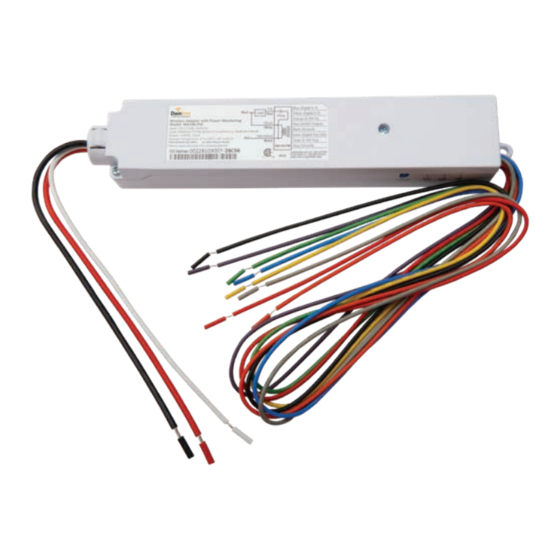
Wireless Adapter
(WA100-PM)
BEFORE YOU BEGIN
Read these instructions completely and carefully.
Save these instructions for future use.
WARNING
Risk of electrical shock. Disconnect power before servicing or
installing product.
Install in accordance with National Electric Code and local codes.
The Daintree WA100-PM Wireless Adapter forms part of the
Daintree Networked wireless controls solution for smart
commercial and industrial buildings. It transmits and receives
messages over the wireless ZigBee
The WA100-PM is an AC powered device that provides On/Off
switching as well as 0-10V analog dimming control for
LED drivers and ballasts.* It also provides power for low voltage
occupancy sensors, photosensors (daylight harvesters),
wall switches, and control signals while it provides the wireless
adaptation that enables them to communicate with the
rest of the wireless control solution. The control signals to and
from these connected devices pass between the WA100-PM
and the Wireless Area Controller in Daintree Controls Software
(DCS) web application.
1
Installation Process
1. Disconnect power before installation. Turn off all power
to affected light fixtures by turning off circuit breakers.
Confirm that power is off at all light fixtures before
continuing installation.
2. Set the WA100-PM DIP switches to support the device(s)
being connected to it. See DIP Switch Settings (page 2).
3. IMPORTANT: Affix the small label with 4-5 digits of the
WA100-PM's IEEE address on the floor Plan to indicate
its location.
4. Mount the WA100-PM in the driver cavity of the light
fixture, or external to the light fixture, or to a junction box
approved for the application. See Mounting (page 12).
5. Connect low voltage wiring from the WA100-PM to the
driver, switch(es) and/or sensors as appropriate for your
application. See Wiring (pages 3-11). Cap any unused wires.
network and controls lights.
®
Risk of injury. Wear safety glasses and gloves during installation and
servicing.
6. Connect line voltage wires from the supply circuit to the
WA100-PM and to the driver as shown in Wiring. Cap any
unused wire.
7. Check load circuits then turn on the circuit breakers to power
up the WA100-PM. The light connected to the WA100-PM turns
On when power is initially applied (and when power is restored
after a power failure).
8. Ensure the WA100-PM green Power
9. Press and hold the blue RESET button on the WA100-PM for
3 seconds to reset the unit. Release the button when the green
Joined LED and the red Error LEDs begin flashing.
10. Perform the installation test appropriate for your application.
See Installation Tests (pages 13-14)
Error/Test — On when the Wireless Adapter is in an error state.
Flashes to indicate unit Reset and during Installation Test Mode (red).
Joined — On when the Wireless Adapter has joined a ZigBee
Flashes to indicate Reset and during sensor Installation Test Mode (green).
Power — On when power is applied to the Wireless Adapter (green).
Installation Guide
WA100-PM | DT113
CAUTION
LED is On.
LED Indicators
Error
Joined
Power
Reset
LED
LED
LED
Button
network.
®
Advertisement
Table of Contents

Related Manuals for Daintree GE Current WA100-PM


Summary of Contents for Daintree GE Current WA100-PM
- Page 1 Install in accordance with National Electric Code and local codes. The Daintree WA100-PM Wireless Adapter forms part of the 6. Connect line voltage wires from the supply circuit to the Daintree Networked wireless controls solution for smart WA100-PM and to the driver as shown in Wiring. Cap any commercial and industrial buildings. It transmits and receives...
-
Page 2: Dip Switch Settings
Daintree Networked Wireless Adapter (WA100-PM) Installation Guide ® WA100-PM Model Variants Figure 2: DIP Switch Table — See DIP switch Mode descriptions for information about each option. The model number WA100 was the original version of the Mode Switch Type Switches 1 to 4 Light Output Switches 5 & 6 adapter and is no longer sold. The WA100-PM model monitors... - Page 3 Daintree Networked Wireless Adapter (WA100-PM) Installation Guide ® Switch Adapter Mode Wiring Switch Type Line voltage wiring connects to the electrical supply circuit and to the driver(s). The Black (Hot) flying lead and the Red (Switched Dimming: operating the connected switch generates Load) flying lead are 14AWG. The White (Neutral) flying lead is dimming and On/Off signals. 18AWG. On/Off (no dimming): operating the connected switch Low voltage 22AWG flying leads provide for connections to generates On/Off signals.
- Page 4 Daintree Networked Wireless Adapter (WA100-PM) Installation Guide ® Wiring Continued Figure 3: Wiring Identification Figure 4: Dimming Light Fixtures DIP Switches Driver Type: Wired Sensor: On/Off + 0-10V None dimming 1 2 3 4 5 6 (ALL OFF) Perform Installation Test Suite 1...
- Page 5 Daintree Networked Wireless Adapter (WA100-PM) Installation Guide ® Wiring Continued Figure 5: On/Off (non-dimming) Light Fixtures DIP Switches Driver Type: This configuration allows the WA100-PM to provide automatic Wired Sensor: On/Off + 0-10V None On/Off switching of light fixtures. dimming 1 2 3 4 5 6 (#4 ON) Perform Installation Test Suite 1 Figure 6: On/Off (non-dimming) Light Fixture(s), Occupancy...
- Page 6 Daintree Networked Wireless Adapter (WA100-PM) Installation Guide ® Wiring Continued Figure 7: Dimming Driver(s), Occupancy Sensor configuration DIP Switches Driver Type: Wired Sensor: This configuration allows the WA100-PM to provide automatic On/Off Occupancy 0-10V dimming control and to switch drivers On/Off based on dimming 1 2 3 4 5 6 occupancy. Set occupancy sensor for minimum time delay.
- Page 7 Daintree Networked Wireless Adapter (WA100-PM) Installation Guide ® Wiring Continued Figure 9: Dimming Light Fixture(s), Photosensor, Occupancy Sensor configuration This configuration allows the WA100-PM to provide automatic DIP Switches 0-10V dimming control and to switch drivers On/Off. Set Driver Type: Wired Sensor: occupancy sensor for minimum time delay. On/Off Photosensor dimming 1 2 3 4 5 6...
- Page 8 Daintree Networked Wireless Adapter (WA100-PM) Installation Guide ® Wiring Continued Figure 11: Bi-level Switching DIP Switches Driver : Wired Sensor: This configuration allows the WA100-PM to switch loads Bi-Level None independently in a bi-level driver (or 2 drivers), providing no 1 2 3 4 5 6 load (0%), partial load (according to the driver/ballast (#3,4 ON) capability) or full load (100%). Perform Installation Test Suite 1 Figure 12: Alternate Switching...
- Page 9 Daintree Networked Wireless Adapter (WA100-PM) Installation Guide ® Wiring Continued Figure 13: Switching a Branch Circuit DIP Switches Driver Type : Wired Sensor: This configuration allows the WA100-PM to provide On/Off On/Off None switching of a branch circuit. (no dimming) 1 2 3 4 5 6 (#4 ON) Perform Installation Test Suite 1 Figure 14: 208V 2-Pole (Phase-to-Phase) wiring...
- Page 10 Daintree Networked Wireless Adapter (WA100-PM) Installation Guide ® Wiring Continued Figure 15: Switching Contactors DIP Switches Driver Type : Wired Sensor: This configuration allows the WA100-PM to provide On/Off On/Off None switching control to an external contactor. (no dimming) 1 2 3 4 5 6 (#4 ON) Perform Installation Test Suite 1...
- Page 11 Daintree Networked Wireless Adapter (WA100-PM) Installation Guide ® Wiring Continued Figure 16: Bypass WA100 switched power and 0-10V dimming control during power failure In the wiring diagram here, while Regular power is supplied to the LVS model RRU-X-UM the WA100-PM provides switched On/Off power and 0-10V dimming control to the fixture driver or ballast. When the RRU-X-UM senses loss of Regular power it passes Emergency power directly to the fixture. It disconnects the WA100-PM switched output and disconnects the WA100-PM dimming control so that the fixture will operate at maximum output during the power failure.
-
Page 12: Using The Mounting Bracket
Daintree Networked Wireless Adapter (WA100-PM) Installation Guide ® Trimming and Dressing Securing Low Voltage Wires 3. Isolate the end of each wire using a wire nut, shrink tubing, or 1. Make sure the unit is NOT powered. equivalent. 2. Cut the unused low voltage wires approximately five 4. Wrap the unused low voltage wires around the side of the inches from where they exit the WA100-PM body. adapter in a bunch, and secure them in place using a white or clear cable tie. Figure 18: Secure unused wires... -
Page 13: Installation Tests
6. Press and hold the blue RESET button on the WA100-PM wired to the same WA100-PM. After you exit the Installation Test for 3 seconds to reset the unit. Release the button mode, the lights turn On and are NOT controlled by the devices when the green Joined LED and the red Error LEDs connected to the WA100-PM. After commissioning the Daintree begin flashing. Networked system, lighting control is determined by configuration settings in the Daintree Controls Software. Test Suite 3: IMPORTANT NOTICES Dimming Driver + Occupancy Sensor + Photosensor 1. Press and immediately release the blue Reset button. The... - Page 14 Daintree Networked Wireless Adapter (WA100-PM) Installation Guide ® Installation Tests Continued Test Suite 8: Test Suite 4: Continued Dimming Driver + Photosensor 4. Operate the switch(es) connected to the WA100-PM and 1. Press and immediately release the blue Reset button. The observe that the lights turn On, Off, and Dim as expected. red Error LED flashes once, then pauses and repeats. 5. Press and immediately release the Reset button to exit 2. C heck that the lights connected to the driver cycle from testing. maximum to minimum brightness then turn Off, 6. Press and hold the blue RESET button on the WA100-PM then repeat. for 3 seconds to reset the unit. Release the button 3. P ress and immediately release the blue Reset button again. when the green Joined LED and the red Error...
-
Page 15: Troubleshooting
When the Daintree Networked is commissioned, time delays are set in the Daintree Controls Software system. These DCS “Off delays” start counting down after the sensor’s internal time delay expires. Therefore, set occupancy sensors for the minimum time delay during the WA100-PM installation. - Page 16 Daintree Networked Wireless Adapter (WA100-PM) Installation Guide ® Plug Load Applications Plug load control functionality for the WA100-PM is made available with WA100-PM firmware provided in version 3.5.3.1. During testing the Plug Load cycles on/off in sync with the lighting load. Relays used to control plug loads must be compliant with UL498 (Attachment Plug and Receptacles) or equivalent. Wiring for Combination Plug Load DIP Switches (Basic Aux Relay) and Dimming Light Driver: On/Off + Wired Sensor: 0-10V dimming.
- Page 17 Daintree Networked Wireless Adapter (WA100-PM) Installation Guide ® Plug Load Applications Continued Wiring for Combination Plug Load (Aux Relay with Input Control Signal) and Dimming Light DIP Switches Driver: Wired Sensor: In the wiring diagram below, the WA100-PM is used to On/Off + 0-10V None control both a dimming light and a plug load circuit. dimming. Plug 1 2 3 4 5 6...
- Page 18 Daintree Networked Wireless Adapter (WA100-PM) Installation Guide ® Plug Load Applications Continued Wiring for Combination Plug Load (Aux Relay with Input Control Signal) and On/Off Light DIP Switches Driver: On/Off Wired Sensor: In the wiring diagram below, the WA100-PM is used to Plug Load: None control both an On/Off light and a plug load circuit. On/Off 1 2 3 4 5 6...
-
Page 19: Specifications
Daintree Networked Wireless Adapter (WA100-PM) Installation Guide ® Specifications WFA100-PM Input Voltage 120-277VAC, 50-60Hz CAUTION Switched Output 15A driver/incandescent @ 120-277VAC RISK OF EXPOSURE IF BATTERY IS REPLACED BY AN Relay 1hp @ 120-230VAC (switched to Hot/Active) INCORRECT TYPE. DISPOSAL OF USED BATTERIES ACCORDING TO THE INSTRUCTIONS. Low Voltage 24VDC; 75mA maximum...
Need help?
Do you have a question about the GE Current WA100-PM and is the answer not in the manual?
Questions and answers