Table of Contents
Advertisement
Quick Links
Daintree
®
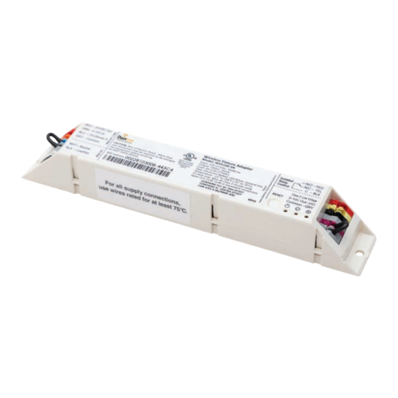
Fixture Adapter
(WFA100-SN)
BEFORE YOU BEGIN
Read these instructions completely and carefully.
Save these instructions for future use.
WARNING
Risk of electrical shock. Disconnect power before servicing or
installing product.
Install in accordance with National Electric Code and local codes.
The Daintree Wireless Fixture Adapter (WFA100-SN)
forms part of Daintree Networked in commercial and industrial
buildings. It transmits and receives messages over the wireless
ZigBee
network and controls lights.
®
Fixture adapters are AC powered devices that provide On/Off
switching as well as 0-10V analog dimming control for ballasts
and LED drivers. The WFA100-SN also provides power and signal
connections for low voltage occupancy sensors and photosensors
(daylight harvesters). The WFA100-SN automatically configures
itself for the type of sensor(s) connected to it.
The WFA100-SN provides the wireless adaptation that enables
connected devices to communicate with the rest of the
wireless lighting control solution. The adapter also serves as
a communication router in the ZigBee wireless mesh network.
Control signals pass between the adapter and the Wireless
Area Controller in the Daintree Networked platform.
1
Installation Process
1. Disconnect power before installation. Turn off all power
to affected light fixtures by turning off circuit breakers.
Confirm that power is off at all light fixtures before
continuing installation.
2. IMPORTANT: Use the provided Fixture and Plan labels to
identify the wireless-adapted fixture location. Attach the Fixture
label to the outside of the fixture. Attach the Plan label at the
fixture location on the facility floor plan.
4. Connect low voltage wiring from the WFA100-SN to the ballast,
and sensors as appropriate for your application. See Wiring
(pages 2-7).
5. Connect line voltage wiring from the supply circuit to the
WFA100-SN and from the WFA100-SN to the ballast.
See Wiring.
Wireless
Risk of injury. Wear safety glasses and gloves during installation and
servicing.
6. Check load circuits then turn on the circuit breakers to power
up the WFA100-SN. The light connected to the WFA100-SN
turns On when power is initially applied (and when power is
restored after a power failure).
7. Ensure the WFA100-SN green Power LED is On.
8. Press and hold the Reset button on the WFA100-SN for
3 seconds to reset it. Release the button when the green
Joined LED and the red Error LEDs begin flashing.
9. Perform the installation test appropriate for your application.
See Installation Tests (pages 9-10).
Error/Test — On when the Wireless Adapter is in an error state.
Flashes to indicate unit Reset and during Installation Test Mode (red).
Joined — On when the Wireless Adapter has joined a ZigBee
Flashes to indicate Reset and during sensor Installation Test Mode (green).
Power — On when power is applied to the Wireless Adapter (green).
Figure 1: LED Indicators
Power
LED
Installation Guide
WFA100-SN | DT111
CAUTION
LED Indicators
®
Joined
Error
LED
LED
network.
Advertisement
Table of Contents

Related Manuals for Daintree GE Current WFA100-SN


Summary of Contents for Daintree GE Current WFA100-SN
- Page 1 Risk of injury. Wear safety glasses and gloves during installation and installing product. servicing. Install in accordance with National Electric Code and local codes. The Daintree Wireless Fixture Adapter (WFA100-SN) 6. Check load circuits then turn on the circuit breakers to power forms part of Daintree Networked in commercial and industrial up the WFA100-SN. The light connected to the WFA100-SN buildings. It transmits and receives messages over the wireless...
- Page 2 Daintree Networked Wireless Fixture Adapter (WFA100-SN) Installation Guide ® Occupancy Sensor Time Delays Wiring If an occupancy sensor is connected to the WFA100-SN, Line voltage wiring connects to the electrical supply circuit the time delay must be set for minimum. When Daintree and to the ballast(s). Low voltage terminals provide connections Networked is commissioned, time delays are set in the for 0-10VDC dimming control signals to dimming ballasts. Daintree DCS web application. These DCS “Off delays” start The WFA100-SN low voltage terminals also supply low voltage counting down after the sensor’s internal time delay expires. power and carry control signals from low voltage occupancy Therefore, set the occupancy sensor for the minimum time sensors and photocells.
- Page 3 Daintree Networked Wireless Fixture Adapter (WFA100-SN) Installation Guide ® Wiring Continued Remove the jumper from the violet and gray terminals before connecting the 0-10V dimming control wires. Figure 4: Dimming Ballasts Perform Installation Test Suite 1 Figure 5: On/Off (non-dimming) Ballasts Perform Installation Test Suite 1...
- Page 4 Daintree Networked Wireless Fixture Adapter (WFA100-SN) Installation Guide ® Wiring Continued This configuration allows the WFA100-SN to provide automatic On/Off switching of ballasts and provides an occupancy sensor input. Set the occupancy sensor for the minimum time delay. Figure 6: On/Off (non-dimming) Ballast(s), Occupancy Perform Installation Test Suite 2 Sensor configuration Figure 5: On/Off (non-dimming) Ballasts This configuration allows the WFA100-SN to provide automatic 0-10V dimming control and to switch ballasts On/Off. It also...
- Page 5 Daintree Networked Wireless Fixture Adapter (WFA100-SN) Installation Guide ® Wiring Continued This configuration allows the WFA100-SN to provide automatic 0-10V dimming control and to switch ballasts On/Off. It also provides an analog photosensor input (0-10V). Remove the jumper from the violet and gray terminals before connecting the 0-10V dimming control wires. Figure 8: Dimming Ballast(s), Photosensor configuration...
- Page 6 Daintree Networked Wireless Fixture Adapter (WFA100-SN) Installation Guide ® Wiring Continued In the wiring diagram below, the WFA100-SN is powered by the Emergency power circuit. Regular power is brought into the fixture from an adjacent fixture and connects to the RRU-X-UM. While Regular power is supplied to the RRU-X-UM the WFA100-SN provides switched On/Off power to the fixtureand controls dimming. When the RRU-X-UM senses loss of Regular power, it passes Emergency power directly to the fixture and disconnects the WFA100-SN switched output. Loss of Regular power to the RRU-X -UM disables the WFA100-SN dimming controland the fixture will operate at maximum output. Figure 10: Bypass WFA100 switched power and 0-10V dimming control during power failure...
- Page 7 Daintree Networked Wireless Fixture Adapter (WFA100-SN) Installation Guide ® Wiring Continued In the wiring diagram below, the WFA100-SN is powered by the Regular power circuit and is installed inside the Regular Fixture. While Regular power is supplied to the RRU-2, the WFA100-SN provides switched On/Off power to the Regular Fixture ballast. The WFA100-SN also controls dimming to the Regular Fixture and the Emergency Fixture. The Emergency Fixture is powered by the Emergency power circuit. The 0-10V dimming circuit from the WFA100-SN is brought into the Emergency Fixture. When the RRU-2 senses loss of Regular power, the RRU-2 disconnects the 0-10V output from the WFA100-SN and the ballast will operate at maximum output from the Emergency power circuit. (If the RRU-2 is not installed, the Emergency Fixture will dim to minimum because the WFA100-SN 0-10V output shorts when the adapter loses power.)
-
Page 8: Important Notices
Daintree Networked Wireless Fixture Adapter (WFA100-SN) Installation Guide ® Mounting Figure 12: Mounting in ballast channel The WFA100-SN is designed to be mounted inside a light fixture. Typically, it is mounted in the ballast channel using two screws A bar code label with the WFA100-SN’s full IEEE address on it is included with the WFA100-SN. This is the Fixture label. Affix this label to the outside of the fixture. Choose a standard location so that when someone looks for fixtures containing an adapter, they will know where to look for the IEEE address bar code label. Figure 13: Mounting Template (observe measurements, illustration may not be actual size). Important Notices Complete Installation Tests... -
Page 9: Installation Tests
Daintree Networked Wireless Fixture Adapter (WFA100-SN) Installation Guide ® Installation Tests Test Suite 3: Dimming or On/Off Ballast + Photosensor All lighting devices, including wireless adapters must be tested 1. Press and immediately release the Reset button. The for proper operation. red Error LED flashes once, then pauses and repeats. 2. Check that the connected lights cycle On and Off, or cycle After mounting, wiring low voltage, wiring line voltage, powering from maximum to minimum brightness then turn Off, up and resetting the unit, perform the recommended Installation then repeat the cycle. Test. The Installation Test mode automatically times out after 3. P ress and immediately release the Reset button again. -
Page 10: Troubleshooting
3 seconds to reset it. Release the button when the same adapter. The control signals from the low voltage devices green Joined LED and the red Error LEDs begin pass through the adapter and are sent wirelessly to the Daintree flashing. Networked platform. Depending on the zone and device Test Suite 6: configuration in the DCS, wireless signals from the WAC to the adapter determine the operation of the light(s). -
Page 11: Specifications
Daintree Networked Wireless Fixture Adapter (WFA100-SN) Installation Guide ® CE Warning message Specifications Input Voltage 120-277VAC, 50-60Hz Sensor (occupancy and photo) wiring lengths above 3m were not considered for immunity. Isolated Relay N/O and N/C contacts Load: 3A@120VAC- -277VAC FCC Warning Message Load Types Electronic Ballast, General Use This equipment has been tested and found to comply with Low Voltage 24VDC; 35mA max the limits for a Class B digital device, pursuant to Part 15 of Output the FCC Rules. These limits are designed to provide reasonable protection against harmful interference in a residential Analog Dimming 22AWG, 600V, UL 1015, plenum rated Max.
Need help?
Do you have a question about the GE Current WFA100-SN and is the answer not in the manual?
Questions and answers