Table of Contents
Advertisement
Quick Links
London Electronics Limited
Thorncote Green, Near Hatch, Sandy, SG19 1PU, England
Tel: 01767 626444 Fax: 01767 626446 International prefix +44
Web site with full catalogue, news, distribution details, http://www.london-electronics.com
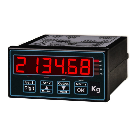
Model INTUITIVE-I
Totalising Digital Process Indicator / Controller
Patent App. Numbers :- UK=GB9820695.6, EU = 99307553.0, USA 09/401738, Canada 2283378
Document Ref:pm65\manuals\INTUITIVE_I
E-Mail easy4u@london-electronics.com
4-20mA / 0-10V input
Max.
Min.
ZERO
SPAN & d.p.
ZERO
SPAN / dp
s
DIGIT
TARE
MAX / MIN
Lineariser
89/336/EEC
0% O/P
100% O/P
ALARMS
OUTPUT
OK
RESET
IEC 1010
Revision:4 Dated: 1 July 2009
AL1
AL2
AL3
AL4
Advertisement
Table of Contents

Subscribe to Our Youtube Channel
Related Manuals for London Electronics INTUITIVE-I


Summary of Contents for London Electronics INTUITIVE-I
- Page 1 London Electronics Limited Thorncote Green, Near Hatch, Sandy, SG19 1PU, England Tel: 01767 626444 Fax: 01767 626446 International prefix +44 E-Mail easy4u@london-electronics.com Web site with full catalogue, news, distribution details, http://www.london-electronics.com Model INTUITIVE-I Totalising Digital Process Indicator / Controller 4-20mA / 0-10V input Max.
-
Page 2: Alphabetic Index
Alphabetic Index Alarm board Configuration Alarms, how to set Analogue Output configuration Analogue output, how to set Calibration Calibration Examples Calibration - Tamper detection Connections Count-By (last digit round-up) adjustment Decimal point position selection Declaration of Conformity Failsafe alarm setting Filter time constant selection General description Getting Started... - Page 3 Important Introductory Notes Please feel welcome to contact us if you need help, have a complaint, or if you have suggestions for improving our products or services. If you contact us about a product you already have, please give us as much information as you can, so we can give you accurate and swift help.
- Page 4 Warnings Please carefully read all warnings and ONLY install the meter when you are sure that you’ve covered all aspects. * Connect the meter according to current IEE regulations and separate all wiring according to IEC1010. * Power supplies to this equipment must be anti-surge fused at 125mA for 230V supply, 250mA for 110V supply or 1A for DC supplies in the range 11-30VDC.
-
Page 5: General Description
General Description This meter has been designed to be simple to configure. It is easy to use because no menu is used. Look at the front panel below... to adjust ZERO you press the ZERO button, to adjust Span you press the SPAN button, to adjust Analogue Output you press the OUTPUT button, to adjust Alarms you press the ALARM button. -
Page 6: Getting Started
Getting Started First, please check that the display will suit all the requirements of your application. Page 4 has some important warnings - please check that all warnings are covered. If you have analogue output or alarm relay options, you may need to configure their boards before installing the meter in a panel. - Page 7 Connections These connectors are only used when options are fitted Analogue Serial ALARM RELAY OUTPUTS Output Output 14 15 16 17 18 19 20 21 22 23 24 25 26 27 REAR VIEW 1 2 3 4 5 6 7 8 9 10 11 12 13 Mains Power model DC Power model INPUT...
- Page 8 Calibration Set switch 1, near the input connector ON and lockout switch OFF 1) How to set SPAN and DECIMAL POINT Press the SPAN button for 3 seconds. You’ll see ‘dC V’ or ‘dC A’ if the meter is set for DC Voltage or DC current. Use the up or down arrow to change, if needed and then press OK.
-
Page 9: Calibration Examples
Calibration Examples 4 to 20mA = 0 to 300m per day flow rate. You want to display total m passed a. Set ‘Int d’ because your flowrate is described in m per day b. Set InHi = 20.000mA c. Set rd Hi to 300 (after 24 hrs at 20mA, the display will reach 300) d. - Page 10 Filter and Last Digit Roundup Press the OK button 5 times to access the filter time constant, which is expressed in seconds. You can use the filter to improve your display stability with fluctuating input signals. Use the UP and DOWN buttons to select a time constant in the range 0 to 5 seconds.
- Page 11 Features Calibration Counter / Tamper detector An internal totaliser counts each calibration. The ‘CAL XX’ value appears for a second or two after you switch the meter on. The number starts at 00 and can go up to FF (255 counts). It doesn’t count changes of setpoints, or changes of filter value or count-by value .
- Page 12 How to install option boards If you want to open the meter to install or modify option boards, follow these steps... 1) Switch off power to the meter and unplug all connectors. 2) Unclip the front bezel. This is easier if you squeeze the top and bottom of the case, near the front.
- Page 13 Alarm Board Configuration & Adjustment For failsafe operation (where contacts open on alarm or when power is lost to the meter) set the jumpers for OPEN CONTACTS and DE-ENERGISE on alarm. To access to the alarm board, first remove power from meter, including any power which might be on the alarm output circuitry.
-
Page 14: Alarm Settings
Alarm settings If you press the ALARMS button momentarily, you can view each of the 4 alarm settings (each press will illuminate in turn AL1, AL2, AL3 and AL4 LEDs). Alarm settings are not locked out by the lockout switch. Max. - Page 15 In-Flight Compensation You can configure the meter to have in-flight compensation, which can improve alarm accuracy in some applications. Here’s how it works..Imagine you have a storage container and you want to empty a certain amount of material from that container into a bin. When the bin reaches the desired weight, the meter will switch off the shutoff valve.
-
Page 16: Analogue Output Configuration
Analogue Output Configuration We always set the meters to suit any requests on your order, so you should not need to adjust the analogue board. If you didn’t specify ranges, but ordered option ‘ANI’, the meter will be set for 4-20mA output. If you ordered ‘ANV’ it will be set for 0-10V. - Page 17 How to adjust your Analogue Output The lockout switch should be set ‘OFF’ to change the analogue output calibration. You can set the analogue output range to suit your display range. The analogue output can be directly proportional or inversely proportional to the display range, for example you can have 4-20mA output for display 0 to100 or for display 100 to 0.
- Page 18 Serial Communications Output Option You can have either an RS232 or an RS422 ASCII output at 1200 baud representing the meter’s displayed value. You can have a continuous transmission of readings, or a single transmission on demand. RS232 O/P on terminal 16 (data+) and terminal 18(common) RS422 O/P on terminals 16 &...
- Page 19 8 Programme Memory Option With the MEM-08 option, you can store up to 8 sets of configuration and calibration data. This is useful if you want to connect a number of different sensors, each with different calibration, to the meter, selected by rotary switch. Each memory location can have its own input/display calibration, alarm settings, and analogue O/P calibration.
-
Page 20: Equipment Specifications
Equipment Specifications Bezel size 48mm high by 96 mm wide (1/8 DIN) Panel Cutout 45 mm high by 92 mm wide Case Depth 125 mm including connectors Weight 300 grammes Case Material Black polycarbonate Connectors Detachable Screw Terminal connectors Power 95-265 VAC or 11-30 VDC optional Burden 8VA maximum... - Page 21 Record of Revisions/Changes 2 October 2001 Page 5 Switches changed Page 17 Analogue output board potentiometer note added. 31 July 2003 Declaration of Conformity amended 3 March 2004 Page 16 - changed reference from Grand Intuitive to Easy Reader Page 19...
- Page 22 Notes...
-
Page 23: Declaration Of Conformity
Signal cabling shall be routed separately to power carrying cabling (includes relay output wiring) All signal cabling shall be screened. The screen shall only be terminated to the power earth terminal Declared as true and correct, for and on behalf of London Electronics Ltd. Warren Court, Beds.
Need help?
Do you have a question about the INTUITIVE-I and is the answer not in the manual?
Questions and answers