Table of Contents
Advertisement
Quick Links
Advertisement
Table of Contents

Subscribe to Our Youtube Channel
Related Manuals for Infranor Xtracontrol DC2


Summary of Contents for Infranor Xtracontrol DC2
- Page 2 Copyright © Infranor GmbH Reproduction and duplication of this document and utilisation and communication of its content is prohibited unless with our express permission. All rights reserved. Infringements will result in compensation for damages. Legal disclaimer The content of this document has been verified for conformity with the hardware and software described therein. It is, however, impossible to rule out all variations.
- Page 3 Initial version 28/01/2015 Corrections, final UL certificate 16/04/2015 Corrections: protection class, UL-symbol; Additions: mounting, note USB- devices, technical data (shock, vibration) 26/04/2016 Corrections: techical data E-terminal, temperatures DC2 new declaration of conformity; update to new EMC Directive © Infranor GmbH...
-
Page 4: Table Of Contents
5.2.3 Block circuit diagram, XtracontrolET2......................32 5.2.4 Digital inputs and outputs, XtracontrolDC2 and XtracontrolEC21..............33 5.2.5 Ethernet..............................37 5.2.6 EtherCAT..............................38 5.2.7 USB................................39 5.2.8 Serial interfaces............................41 5.2.9 CAN Bus..............................43 5.2.10 Analogue inputs............................44 6 OPERATION........................50 © Infranor GmbH... - Page 5 11.1 Standards..............................78 11.2 UL certificate.............................. 79 11.3 Declaration of conformity......................... 82 11.4 Notes on copyright and software licences.....................83 12 CUSTOMER SERVICES / ADDRESSES.................84 12.1 Customer services........................... 84 12.2 Addresses..............................84 13 APPENDIX........................85 13.1 Table of figures............................85 © Infranor GmbH...
-
Page 6: General Information
Individual instruction or list of instructions which can be carried out in any order. … List of instructions which must be carried out in the order given. … Additional product information Design of warnings: WARNUNG Danger type and source Optional Short description and possible consequences additional Preventive measures ▶ symbols © Infranor GmbH... -
Page 7: Hazard Categories And Indications
Possible minor injuries Non-compliance with the safety features may result in minor injuries. Take preventive measures. ▶ NOTICE Possible damage to property Non-compliance with the safety features may result in damage to property. Take preventive measures. ▶ Further information © Infranor GmbH... -
Page 8: Qualified Personnel
Intended use The devices belong to the Infranor modular automation system based on the CAN bus. This is a modular automation system for industrial control applications within the medium to high performance range. This extends the communications capabilities to include EtherCAT, Profinet, Modbus and others. -
Page 9: Transport And Storage
The delivery documentation contains important information about the device and is part of the product. If you discover damage in transport or the contents do not match the order: Inform the supplier immediately. © Infranor GmbH... -
Page 10: Safety
Secure the system against being switched on again. Disconnect the device from the system. The casing of the device must not be opened. If work on the internal parts of the device is necessary, contact the manufacturer (see “Addresses”). ▶ © Infranor GmbH... -
Page 11: Product Description
The terminals show the CODESYS Web visualisation or the CODESYS Target visualisation, irrespective of whether the visualisation originates from a Infranor PLC control unit or some other compatible CODESYS control unit. XtracontrolDC2 and XtracontrolEC21 controllers can be connected using various different interfaces and have in addition their own digital and analogue inputs / outputs. -
Page 12: Overview
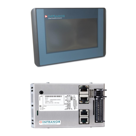
Function key (Reset and Run/Stop) Analogue inputs Terminating resistor CAN (120 Ohm) USB 2.0 Terminating resistor RS-485 (120 Ohm) Ethernet (ETH0) µSD microSD card connection (optional) EtherCAT (ETH1) LEDs: PWR, Run/Stop, Error 1Required only for protection rating IP65 © Infranor GmbH... -
Page 13: Overview Xtracontroldc2.07
Function key (Reset and Run/Stop) Analogue inputs Terminating resistor CAN (120 Ohm) USB 2.0 Terminating resistor RS-485 (120 Ohm) Ethernet (ETH0) µSD microSD card connection (optional) EtherCAT (ETH1) LEDs: PWR, Run/Stop, Error 2Required only for protection rating IP65 © Infranor GmbH... -
Page 14: Overview Xtracontrolet2.04
Power supply Securing clip (qty 4) USB 2.0 Twist-lock catch (qty 4) Ethernet (ETH0) Function key (Reset and Run/Stop) Debug interface LEDs: PWR, Run/Stop, Error µSD microSD card connection (for future applications) 3Required only for protection rating IP65 © Infranor GmbH... -
Page 15: Overview Xtracontrolet2.07
Power supply Securing clip (qty 6) USB 2.0 Twist-lock catch (qty 6) Ethernet (ETH0) Function key (Reset and Run/Stop) Debug interface LEDs: PWR, Run/Stop, Error µSD microSD card connection (for future applications) 4Required only for protection rating IP65 © Infranor GmbH... -
Page 16: Overview Xtracontrolec21
Analogue inputs Function key (Reset and Run/Stop) USB 2.0 Terminating resistor CAN (120 Ohm) Ethernet (ETH0) Terminating resistor RS-485 (120 Ohm) EtherCAT (ETH1) µSD microSD card connection (optional) RS-232 / RS-485 LEDs: PWR, Run/Stop, Error CAN bus © Infranor GmbH... -
Page 17: Scope Of Delivery And Accessories
The first Ethernet interface is used for standard Ethernet connections. TCP/IP and UDP/IP protocols permit flexible connections to visualisation software, higher-level control units and to the IT infrastructure. The second Ethernet interface is used as an EtherCAT master interface. Other protocols available for the Ethernet interfaces: PROFINET, BACnet and Modbus. © Infranor GmbH... - Page 18 A software interface permits the current time and date to be set and read on a real-time clock with battery back-up. microSD card The standard commercial microSD card interface allows data to be written to memory cards or read from memory cards. © Infranor GmbH...
- Page 19 2 Ethernet 10/100 Base T interfaces (2 interface: EtherCAT master interface 1 CAN interface 2 serial interfaces (1x RS-485; 1x RS-232) 1 µSD card slot Onboard I/O (digital and analogue) Real-time clock © Infranor GmbH...
-
Page 20: Installation
The max. surrounding air temperature in the control cabinet must not exceed 55°C during operation. The support material for the installation cut-out must be flat, sufficiently stable, and be from 1 to 3 mm thick. © Infranor GmbH... - Page 21 Cut a rectangular installation cut-out in the support material: ▶ Height: 86.8 mm Width: 123.8 mm Max. corner radius: 3.0 mm Thickness of the support material: Protection class IP65 with twist-lock catches: only at 1.5–3.0 mm Optimal: 1.5–2.0 mm Max.: 3.0 mm © Infranor GmbH...
-
Page 22: Installation Cut-Out, Xtracontroldc2.07 And Xtracontrolet2.07
Installation on uneven support material can lead to mechanical stresses and cracks in the front face or malfunctioning of the touch screen. Make sure that the mounting points of the device are all in a ▶ common plane, with no more than maximum ±0.5 mm variation. © Infranor GmbH... - Page 23 Cut a rectangular installation cut-out in the support material: ▶ Height: 136.5 mm Width: 187.0 mm Max. corner radius: 3.0 mm Thickness of the support material: Protection class IP65 with twist-lock catches: only at 1.5–3.0 mm Optimal: 1.5–2.0 mm Max.: 3.0 mm © Infranor GmbH...
-
Page 24: Installation, Xtracontroldc2 And Xtracontrolet2
Fig. 11: Installation in an installation cut-out, example with 4 securing clips Making sure the alignment is correct, push the device evenly into the installation cut-out until the 2 or 3 securing clips snap the device tight. © Infranor GmbH... - Page 25 Device with twist-lock catches: Secure the twist-lock catches by turning them with a T9x50 screwdriver. Apply maximum 0.4 Nm torque. The protection rating IP65 at the front face is achieved only when the twist-lock catches are used correctly. © Infranor GmbH...
-
Page 26: Installation, Xtracontrolec21
Insert the device into the mounting rail from above so that the clip is resting on the rail. Push the device down against the mounting surface so that the retaining spring engages. The device is now engaged on the mounting rail. © Infranor GmbH... -
Page 27: Connection
Installation All connections and cables must be laid out so as to prevent inductive and capacitive interference causing any ▶ damage to the device. Ensure that the infeed lines provide adequate current and voltage carrying capacity. ▶ © Infranor GmbH... -
Page 28: Connecting The Power Supply To The Xtracontroldc2 And Xtracontrolec21
Power supply 24 V DC (–15 %/+20 %) (PLC internal processing) max. 1.2 A – The following counterparts have been tested for the SC-SMT 3.5 (Weidmüller) plug-in connector and are approved for use with the device: BLZF 3.50/12/180 © Infranor GmbH... -
Page 29: Connecting The Power Supply To The Xtracontrolet2
Power supply 24 V DC (–15 %/+20 %) max. 1.2 A – The following counterparts have been tested for the SC-SMT 3.5 (Weidmüller) plug-in connector and are approved for use with the device: BLZF 3.5/02/180 (F, LR, LH) SN BK © Infranor GmbH... -
Page 30: Data Connections
User Manual V1.3 | XtracontrolDC2, XtracontrolET2, XtracontrolEC21 Data connections 5.2.1 Block circuit diagram, XtracontrolDC2 Fig. 16: Block circuit diagram, XtracontrolDC2 © Infranor GmbH... -
Page 31: Block Circuit Diagram, Xtracontrolec21
User Manual V1.3 | XtracontrolDC2, XtracontrolET2, XtracontrolEC21 5.2.2 Block circuit diagram, XtracontrolEC21 Fig. 17: Block circuit diagram, XtracontrolEC21 © Infranor GmbH... -
Page 32: Block Circuit Diagram, Xtracontrolet2
User Manual V1.3 | XtracontrolDC2, XtracontrolET2, XtracontrolEC21 5.2.3 Block circuit diagram, XtracontrolET2 Fig. 18: Block circuit diagram, XtracontrolET2 © Infranor GmbH... -
Page 33: Digital Inputs And Outputs, Xtracontroldc2 And Xtracontrolec21
DI 2 digital input DI 3 digital input DI 4 digital input DO 1 digital output DO 2 digital output DO 3 digital output DO 4 digital output 9…12 – Power supply (see “Power supply”) © Infranor GmbH... - Page 34 – current) Rated current at “1” signal 0.5 A – Total current of all outputs max. 2 A – Parallel circuit in two max. 1 A Maximum permissible value with a logical outputs connection to increase power © Infranor GmbH...
- Page 35 Applies for transitions from 0 to 1 and 1 to 0 Signal evaluation cyclical Dependent on the cycle time set in the programming system Protection against – reverse polarity Potential isolation – Status display One orange LED per input Lights at logical 1 © Infranor GmbH...
- Page 36 User Manual V1.3 | XtracontrolDC2, XtracontrolET2, XtracontrolEC21 Fig. 21: Circuit diagram of the principles of positive switching input Fig. 22: Operating ranges of the digital inputs (type 1/3) Item Designation Item Designation “ON” range Transition range Signal-noise ratio < 1 V “OFF” range © Infranor GmbH...
-
Page 37: Ethernet
Assignment TX– RX– LEDs Colour Meaning to IEEE 802.3 clause 25 LNK/RCV yellow Link, Data Receive Flashing: connection active; data transfer in progress Off: no connection established SPEED green On = 100 Mbit/s Off = 10 Mbit/s © Infranor GmbH... -
Page 38: Ethercat
Assignment TX– RX– LEDs Colour Meaning to IEEE 802.3 clause 25 LNK/RCV yellow Link, Data Receive Flashing: connection active; data transfer in progress Off: no connection established SPEED green On = 100 Mbit/s Off = 10 Mbit/s © Infranor GmbH... -
Page 39: Usb
Before using a USB device, check carefully its power requirements. ▶ NOTICE Failures and malfunctions when connected directly to signal ground! Only use USB-devices that do not have a direct connection between ▶ signal ground and housing. © Infranor GmbH... - Page 40 Either the first partition on the USB stick, or, if the memory is not partitioned, the entire memory will be connected, i.e., the respective directory appears automatically. The X represents a number from 1 (first USB device) to 8 (last/max. USB device). The USB interface plug is designed to withstand 1,000 plugging and unplugging cycles. © Infranor GmbH...
-
Page 41: Serial Interfaces
▶ Fig. 27: RS-485 switchable terminating resistor As far as possible, the assignment of the interfaces should be carried out in accordance with the specifications given in “MODBUS over Serial Line; Specification and Implementation Guide V1.02”. © Infranor GmbH... - Page 42 Check the topology and line lengths to determine whether additional connection to GND are necessary. ▶ For electrically isolated interfaces with connections to the reference ground at one point: link to GND. ▶ Ω Where necessary, provide an attenuated link to GND (e.g. via 200 ) at multiple points. ▶ © Infranor GmbH...
-
Page 43: Can Bus
ISO GND If the CAN interface is located at the start or end of the CAN bus topology: Ω Set switch S2 to ON in order to switch on the 120 terminal resistance between CAN_L and CAN_H. ▶ © Infranor GmbH... -
Page 44: Analogue Inputs
The following counterparts have been tested for the SC-SMT 3.5 (Weidmüller) plug-in connector and are approved for use with the device: Weidmüller B2CF 3.50/06/180(F) SN BK Fig. 29: Analogue inputs X2 Analogue inputs X2 Assignment Assignment AI1 (U/T) AI3 (U/T) AGND AGND AI2 (U) AI4 (U) © Infranor GmbH... - Page 45 1,000 ms / 1,000 measurements is issued each millisecond (or, in the case of operating mode AIPT, the average for the last 250 ms / 1,000 measurements). The filtering can be activated and configured using CODESYS V3. The sampling rate is constant. It can only be filtered with a whole multiple of the sampling rate. © Infranor GmbH...
- Page 46 Unsymmetrical voltage metering (single-ended) Reference potential AGND – Dynamic characteristics Analogue filtering Second-grade low- – pass filter; cut-off frequency 650 Hz Greatest temporary 1% of measuring range – deviation during electrical error testing according to IEC 61131-2 © Infranor GmbH...
- Page 47 2-wire measurement or 3-wire measurement Reference potential AGND – Dynamic characteristics Analogue filtering Second-grade low-pass – filter; cut-off frequency 650 Hz Greatest temporary 1% of measuring range – deviation during electrical error testing according to IEC 61131-2 © Infranor GmbH...
- Page 48 Do not connect to the common GND. The required connections can already be found on the circuit board. ▶ Cables to the analogue sensors/encoders should be connected as directly as possible (avoid the use of ▶ terminals and terminal blocks). © Infranor GmbH...
- Page 49 The nearest AI (U) connection is used to compensate the resistance in the cable. It can only be used directly in conjunction with the following AI (U/T) channel. Channels 1 and 2, and also channels 3 and 4 each form a pair for 3- wire measurement. © Infranor GmbH...
-
Page 50: Operation
The device does not have an on/off switch. The device starts automatically when the system is switched on or the power is connected. Switching off The device is switched off when the system is switched off or the power supply is disconnected. © Infranor GmbH... -
Page 51: Network Start-Up
Open a web browser on the programming computer. Enter the IP address of the device into the web browser. The login screen will appear. Fig. 32: login window Use the following user name and password to log into the device: Name: admin Password: admin © Infranor GmbH... - Page 52 In order to activate all of the modified settings, reboot the device: Disconnect the device temporarily from the power supply – or – Click on “Reboot” in the web interface and then confirm on the next screen by clicking on “Reboot Module”. © Infranor GmbH...
-
Page 53: Xtracontrolet2
After startup the current network settings are displayed (server IP, IP-address and netmask). Fig. 35: Startup page with network settings Press the button ”Configuration”. A page with further information appears. Fig. 36: Info page Press the button ”Next”. The page with the current network settings of the device appears. © Infranor GmbH... - Page 54 Fig. 39: Lifeguard-Einstellung ändern Change the lifeguard setting via the button ”Change” according to the version of the controller: CODESYS V2: ”Infranor VNC LG” CODESYS V3: ”Ping LG” Skip the following pages via the button ”Next” until the page with the summary of the network settings appears.
- Page 55 The main screen of the device appears. – or – Press the button ”Save”. The settings are saved and the device reboots automatically. Connect the device to the controller using a network cable. The device is now configured and ready for use. © Infranor GmbH...
-
Page 56: Xtracontrolec21
Open a web browser on the programming computer. Enter the IP address of the device into the web browser. The login screen will appear. Fig. 42: login window Use the following user name and password to log into the device: Name: admin Password: admin © Infranor GmbH... - Page 57 Disconnect the device temporarily from the power supply – or – Click on “Reboot” in the web interface and then confirm on the next screen by clicking on “Reboot Module”. The device is now configured and ready for use. © Infranor GmbH...
-
Page 58: Operation
Fig. 45: Location of the operating status LEDs Meaning PWR (green) shows that the power supply to the electronics is correct. Run/Stop shows the system statuses and CODESYS operating (yellow/green/red) statuses. Error (red) shows the device has been stopped due to an error. © Infranor GmbH... -
Page 59: Start/Stop
Function key (S1) Operating status Action Command Boot phase Press Change to maintenance mode CODESYS PLC/ Press quickly Change between PLC run and stop mode. CP1131-P Press and hold Stop PLC with reset of variables (cold reset) © Infranor GmbH... -
Page 60: Real Time Clock With Battery Back-Up Xtracontroldc2 And Xtracontrolec21
The life cycle of the gold-plated contacts is up to 10,000 plugging and unplugging cycles. The microSD card drive has a push-in/push-out insertion and ejection mechanism. To avoid malfunction, the microSD card may not be removed by pulling. © Infranor GmbH... -
Page 61: Troubleshooting
XX corresponds to the last 2 digits of the device serial number. Exception: 00 becomes 100. Correct the network settings and make a note of them. Restart the device. Maintenance mode is turned off automatically. The device is now configured and ready for use. © Infranor GmbH... -
Page 62: Maintenance / Upkeep
If the device is used correctly it should not require maintenance. Make sure all the ventilation holes are kept free of obstructions. ▶ Do not open the device. If work is required on the device necessary contact customer service. ▶ © Infranor GmbH... -
Page 63: Cleaning
Concentrated hydrochloric acid Petroleum White spirit Petrol Engine oil Diesel Gear oil Brake fluid Anti-freeze Hydraulic oil Condiments Lemon juice Tomato juice Mustard Tomato ketchup © Infranor GmbH... -
Page 64: Resistance Of The Front Diaphragm
Caustic potash (potassium hydroxide) < 2 % Sodium hydroxide 50 % Refrigerant (Hysol X) Diesel oil Castor oil Silver nitrate 20 % Ethyl acetate Acetaldehyde Fluorochlorinated hydrocarbons Glycerine Isopropanol © Infranor GmbH... - Page 65 Grape juice Milk Ariel Persil Wisk Lenor Downey Ajax Domestos Vortex Windex Application of less than 1 hour Glacial acetic acid (pure acetic acid) © Infranor GmbH...
-
Page 66: Uninstallation
XtracontrolDC2.04 and XtracontrolET2.04: 4 securing clips (2 at the bottom, 2 at the top) XtracontrolDC2.07 and XtracontrolET2.07: 6 securing clips (3 at the bottom, 3 at the top) Push the device sufficiently far out of the installation cut-out that the securing clips are no longer engaged. © Infranor GmbH... - Page 67 User Manual V1.3 | XtracontrolDC2, XtracontrolET2, XtracontrolEC21 Fig. 48: Pushing the device out of the installation cut-out Push the device evenly forwards out of the installation cut-out. © Infranor GmbH...
-
Page 68: Uninstallation, Xtracontrolec21
Use the slotted screwdriver to pull the retaining spring down fully and free the device below the mounting rail. Pull the lower device catch off the mounting rail. Push the device up and remove it from the mounting rail. © Infranor GmbH... -
Page 69: Disposal
Dispose of the electronic scrap in accordance with the national laws and regulations. ▶ Check that the battery is fully discharged. ▶ Dispose of the battery in accordance with the national laws and regulations, via an authorised collection point. ▶ © Infranor GmbH... -
Page 70: Technical Data
Supply voltage +24 V DC (–15 % / +20 %) SELV max. Alternating current proportion Power consumption typ. 0.3 A, max. 3 A at +24 V DC, fused depending on the load on the Protection against reverse © Infranor GmbH... - Page 71 Ambient temperature –40…+85 °C (rel. atmospheric humidity (without loss of functionality after 0.5 million activations at –40 °C) < 10 %) Use outdoors Like all polyester-based membranes, Autoflex is unsuitable for long- term exposure to direct sunlight. © Infranor GmbH...
-
Page 72: Xtracontrolet2
+24 V DC (–15 % / +20 %) SELV max. Alternating current proportion 5% Power consumption typ. 0.3 A, max. 1.2 A at +24 V DC Protection against reverse polarity Ethernet interfaces No. / type of interface 1x 10/100 Base T Connection system RJ45 © Infranor GmbH... - Page 73 Ambient temperature –40…+85 °C (rel. atmospheric humidity (without loss of functionality after 0.5 million activations at –40 °C) < 10 %) Use outdoors Like all polyester-based membranes, Autoflex is unsuitable for long- term exposure to direct sunlight. © Infranor GmbH...
-
Page 74: Xtracontrolec21
RJ45 Protocols TCP/IP, Modbus TCP, BACnet, Profinet EtherCAT interfaces No. / type of interface 1x EtherCAT (EtherCAT master) Connection system RJ45 USB interfaces No. / type of interface 1x host USB 2.0 / USB plug port A © Infranor GmbH... -
Page 75: Identification Plate
Supply voltage Version (delivery version; as-delivered Identification no. condition) (article no. and serial no.) CE mark Device type description Date of manufacture (year/calendar week) The ‘Version’ field (delivered version) specifies the ex works condition of the module. © Infranor GmbH... -
Page 76: Identification
User Manual V1.3 | XtracontrolDC2, XtracontrolET2, XtracontrolEC21 10.5 Identification The characteristics of the device can be decoded from the identification key. Fig. 51: XtracontrolDC2 identification key © Infranor GmbH... - Page 77 User Manual V1.3 | XtracontrolDC2, XtracontrolET2, XtracontrolEC21 Fig. 52: XtracontrolET2 identification key Fig. 53: XtracontrolEC21 identification key © Infranor GmbH...
-
Page 78: Standards And Certificates
User Manual V1.3 | XtracontrolDC2, XtracontrolET2, XtracontrolEC21 Standards and certificates 11.1 Standards Applicable directives EMC directive 2014/30/EC Applicable standards PLC standard EN 61131-2:2008-4 Emission standards EN 61000-6-3:2012-11 Safety provisions DIN EN 61010-2-201 © Infranor GmbH... -
Page 79: Ul Certificate
User Manual V1.3 | XtracontrolDC2, XtracontrolET2, XtracontrolEC21 11.2 UL certificate Fig. 54: UL certificate page 1 of 2 © Infranor GmbH... - Page 80 User Manual V1.3 | XtracontrolDC2, XtracontrolET2, XtracontrolEC21 Fig. 55: UL certificate page 2 of 2 The complete UL certificate can be ordered at Infranor. © Infranor GmbH...
- Page 81 User Manual V1.3 | XtracontrolDC2, XtracontrolET2, XtracontrolEC21 The devices are authorised to use the following mark: Fig. 56: cULus authorisation The devices have been awarded cULus authorisation according to standard UL 61010-2-201 NRAQ/7. Link: http://database.ul.com/cgi-bin/XYV/cgifind.new/LISEXT/1FRAME/index.html UL File Number: E242595 © Infranor GmbH...
-
Page 82: Declaration Of Conformity
User Manual V1.3 | XtracontrolDC2, XtracontrolET2, XtracontrolEC21 11.3 Declaration of conformity Fig. 57: Declaration of conformity The complete Declaration of conformity can be ordered at Infranor. © Infranor GmbH... -
Page 83: Notes On Copyright And Software Licences
Mozilla Public License (MPL) FreeType License (FTL) The source code of the free software can be requested at cost by contacting the customer service of Infranor within three years after delivery of the device. © Infranor GmbH... -
Page 84: Customer Services / Addresses
CAN in Automation e.V. (CiA) Am Weichselgarten 26 91058 Erlangen headquarters@can-cia.de www.can-cia.de EtherCAT Technology Group ETG Headquarters Ostendstraße 196 90482 Nürnberg info@ethercat.org www.ethercat.org Beuth Verlag GmbH, 10772 Berlin VDE-Verlag GmbH, 10625 Berlin VDE Verlag GmbH, 10625 Berlin Internet research: www.iec.ch © Infranor GmbH... -
Page 85: Appendix
Fig. 45: Location of the operating status LEDs......................... 58 Fig. 46: function key (S1)..............................59 Fig. 47: Undo the securing clips............................66 Fig. 48: Pushing the device out of the installation cut-out....................67 Fig. 49: Uninstalling the device............................68 Fig. 50: Identification plate (example)..........................75 © Infranor GmbH... - Page 86 Fig. 52: XtracontrolET2 identification key......................... 77 Fig. 53: XtracontrolEC21 identification key........................77 Fig. 54: UL certificate page 1 of 2............................79 Fig. 55: UL certificate page 2 of 2............................80 Fig. 56: cULus authorisation.............................. 81 Fig. 57: Declaration of conformity............................. 82 © Infranor GmbH...
- Page 87 Infranor Group Infranor worldwide Switzerland Infranor creates added value for its customers by providing tailor-made motion solutions Germany France Based on strong working relationships, Infranor offers extensive market know- how, comprehensive engineering skills and a wide range of high-quality Italy...
Need help?
Do you have a question about the Xtracontrol DC2 and is the answer not in the manual?
Questions and answers