
Related Manuals for Yamaha Delight XC115S 2013


Summary of Contents for Yamaha Delight XC115S 2013
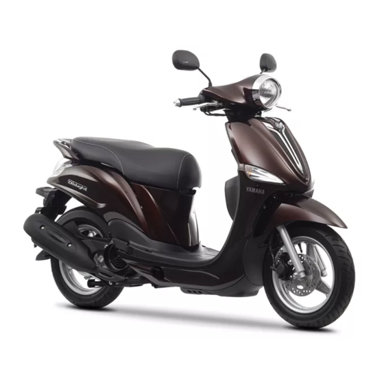
- Page 1 Read this manual carefully before operating this vehicle. OWNER’S MANUAL XC115S 2EP-F8199-E0...
- Page 2 EAU46090 Read this manual carefully before operating this vehicle. This manual should stay with this vehicle if it is sold.
- Page 3 EAU10113 Welcome to the Yamaha world of motorcycling! As the owner of the XC115S, you are benefiting from Yamaha’s vast experience and newest technology regarding the design and manufacture of high-quality products, which have earned Yamaha a reputation for dependability.
- Page 4 IMPORTANT MANUAL INFORMATION EAU10133 Particularly important information is distinguished in this manual by the following notations: This is the safety alert symbol. It is used to alert you to potential personal injury hazards. Obey all safety messages that follow this symbol to avoid possible injury or death.
- Page 5 IMPORTANT MANUAL INFORMATION EAU37431 XC115S OWNER’S MANUAL ©2013 by Thai Yamaha Motor Co., Ltd. 1st edition, March 2013 All rights reserved. Any reprinting or unauthorized use without the written permission of Thai Yamaha Motor Co., Ltd. is expressly prohibited. Printed in Thailand.
-
Page 6: Table Of Contents
TABLE OF CONTENTS SAFETY INFORMATION ....1-1 FOR YOUR SAFETY – Tires ..........6-15 Further safe-riding points ....1-5 PRE-OPERATION CHECKS ..... 4-1 Cast wheels ......... 6-17 Checking the front brake lever DESCRIPTION ........2-1 OPERATION AND IMPORTANT free play ........6-17 Left view ..........2-1 RIDING POINTS......... - Page 7 TABLE OF CONTENTS SCOOTER CARE AND STORAGE ...7-1 Matte color caution ......7-1 Care ..........7-1 Storage ...........7-4 SPECIFICATIONS ......8-1 CONSUMER INFORMATION.....9-1 Identification numbers ....9-1...
-
Page 8: Safety Information
SAFETY INFORMATION ● Never operate a scooter without spicuous appears to be very effec- EAU1026A proper training or instruction. Take tive in reducing the chance of this training course. Beginners type of accident. Be a Responsible Owner should receive training from a cer- Therefore: As the vehicle’s owner, you are respon- tified instructor. - Page 9 SAFETY INFORMATION ● Many accidents involve inexperi- • Always signal before turning or Protective Apparel enced operators. In fact, many op- changing lanes. Make sure that The majority of fatalities from scooter erators who have been involved in other motorists can see you. accidents are the result of head inju- ●...
- Page 10 SAFETY INFORMATION Avoid Carbon Monoxide Poisoning ● Do not run engine outdoors where ● Cargo accessory weight All engine exhaust contains carbon engine exhaust can be drawn into should be kept as low and close to monoxide, a deadly gas. Breathing car- a building through openings such the scooter as possible.
- Page 11 Yamaha accessories, which are avail- characteristics can put you and others effects. Wind may attempt to lift able only from a Yamaha dealer, have at greater risk of serious injury or death. the scooter, or the scooter may been designed, tested, and approved...
-
Page 12: Further Safe-Riding Points
SAFETY INFORMATION Aftermarket Tires and Rims straps carefully so the straps will EAU10373 Further safe-riding points The tires and rims that came with your not rub against painted surfaces ● Be sure to signal clearly when scooter were designed to match the during transport. - Page 13 SAFETY INFORMATION ● Always wear a helmet, gloves, trousers (tapered around the cuff and ankle so they do not flap), and a bright colored jacket. ● Do not carry too much luggage on the scooter. An overloaded scoot- er is unstable. Use a strong cord to secure any luggage to the carrier (if equipped).
-
Page 14: Description
DESCRIPTION EAU10410 Left view 1. Luggage hook (page 3-10) 2. Front storage compartment (page 3-9) 3. Rear storage compartment (page 3-9) 4. Seat (page 3-7) 5. Rear turn signal light (page 6-27) 6. Tail/brake light (page 6-27) 7. Air filter element (page 6-13) 8. -
Page 15: Right View
DESCRIPTION EAU10420 Right view 1. Owner’s tool kit (page 6-2) 2. Battery (page 6-23) 3. Main fuse (page 6-25) 4. Front brake fluid reservoir (page 6-19) 5. Headlight (page 6-26) 6. Front turn signal light (page 6-28) -
Page 16: Controls And Instruments
DESCRIPTION EAU10430 Controls and instruments 1. Fuel tank cap (page 3-5) 2. Left handlebar switches (page 3-3) 3. Rear brake lever (page 3-4) 4. Speedometer (page 3-3) 5. Fuel meter (page 3-3) 6. Front brake lever (page 3-4) 7. Right handlebar switch (page 3-3) 8. -
Page 17: Instrument And Control Functions
INSTRUMENT AND CONTROL FUNCTIONS To lock the steering EAUU1030 EAU10650 Main switch/steering lock All electrical systems are supplied with power, the headlight, meter lighting, taillight and auxiliary light come on, and the engine can be started. The key can- not be removed. EAU10661 LOCK All electrical systems are off. -
Page 18: Keyhole Cover
If the vehicle turns over, and af- 1 2 3 ter placing it upright, ensure that there is no fuel leakage. If fuel is leaking, have a Yamaha dealer check the vehicle. 1. Keyhole cover receptacle 2. “SHUT” button 1. Engine trouble warning light “... -
Page 19: Speedometer Unit
This warning light comes on if a prob- Left lem is detected in the electrical circuit monitoring the engine. If this occurs, have a Yamaha dealer check the self- diagnosis system. The electrical circuit of the warning light can be checked by turning the key to “ON”. -
Page 20: Front Brake Lever
INSTRUMENT AND CONTROL FUNCTIONS EAU12400 EAU12901 EAU12951 Dimmer switch “ ” Front brake lever Rear brake lever Set this switch to “ ” for the high beam and to “ ” for the low beam. EAU12460 Turn signal switch “ ”... -
Page 21: Fuel Tank Cap
INSTRUMENT AND CONTROL FUNCTIONS EAUU1161 EAU13212 Fuel tank cap Fuel Make sure there is sufficient gasoline in the tank. EWA10881 WARNING Gasoline and gasoline vapors are extremely flammable. To avoid fires and explosions and to reduce the risk of injury when refueling, follow 1. -
Page 22: Catalytic Converter
● Do not allow the engine to idle Your Yamaha engine has been de- more than a few minutes. Long signed to use regular unleaded gaso- idling can cause a build-up of line with a research octane number of heat. -
Page 23: Seat
INSTRUMENT AND CONTROL FUNCTIONS To open the seat from the “LOCK” ECA10701 EAUU1173 Seat NOTICE position Use only unleaded gasoline. The use To open the seat of leaded gasoline will cause unre- 1. Place the motorcycle on the cen- pairable damage to the catalytic terstand. -
Page 24: Helmet Holders
INSTRUMENT AND CONTROL FUNCTIONS From the “ON” position, turn the To release a helmet from a helmet EAU37481 Helmet holders key clockwise to “SEAT”. holder 3. Fold the seat up. Open the seat, remove the helmet from the helmet holder, and then close the To close the seat seat. -
Page 25: Storage Compartments
INSTRUMENT AND CONTROL FUNCTIONS Rear storage compartment ● Since the storage compartment EAU56010 Storage compartments The rear storage compartment is locat- accumulates heat when ex- ed under the seat. Use this compart- posed to the sun and/or the en- Front storage compartment ment for large items. -
Page 26: Luggage Hook
INSTRUMENT AND CONTROL FUNCTIONS this system regularly and have a EAUT1072 EAU15305 Luggage hook Sidestand Yamaha dealer repair it if it does not The sidestand is located on the left side EWAT1031 function properly. WARNING of the frame. Raise the sidestand or ●... -
Page 27: Ignition Circuit Cut-Off System
INSTRUMENT AND CONTROL FUNCTIONS EAUT1095 Ignition circuit cut-off system Check the operation of the sidestand switch according to the following proce- dure. 3-11... - Page 28 The vehicle must be placed on the center- stand during this inspection. Put the sidestand up. • If a malfunction is noted, have a Yamaha dealer check the system before riding. Push the start switch while applying either of the brake levers. The engine will start.
-
Page 29: For Your Safety - Pre-Operation Checks
• Check vehicle for oil leakage. Final transmission oil • Check vehicle for oil leakage. 6-12 • Check operation. • If soft or spongy, have Yamaha dealer bleed hydraulic system. • Check brake pads for wear. Front brake • Replace if necessary. 6-18, 6-19 •... - Page 30 • Make sure that operation is smooth. • Check throttle grip free play. Throttle grip 6-15, 6-20 • If necessary, have Yamaha dealer adjust throttle grip free play and lubricate cable and grip housing. • Make sure that operation is smooth. Control cables 6-20 •...
-
Page 31: Operation And Important Riding Points
See page 5-3 for engine break-in in- gle sensor to stop the engine in case of understand, ask your Yamaha dealer. structions prior to operating the ve- a turnover. To start the engine after a EWA10271 hicle for the first time. -
Page 32: Starting Off
OPERATION AND IMPORTANT RIDING POINTS ECA11042 EAU45091 EAU16780 Starting off Acceleration and deceleration NOTICE 1. While pulling the rear brake lever For maximum engine life, never ac- with your left hand and holding the celerate hard when the engine is grab bar with your right hand, push cold! the scooter off the centerstand. -
Page 33: Braking
OPERATION AND IMPORTANT RIDING POINTS EAU16793 EAU16820 EAU16830 Braking Tips for reducing fuel con- Engine break-in sumption There is never a more important period EWA10300 WARNING in the life of your engine than the period Fuel consumption depends largely on ●... -
Page 34: Parking
● Do not park near grass or other cleaned. If any engine trouble flammable materials which should occur during the engine might catch fire. break-in period, immediately have a Yamaha dealer check the vehicle. [ECA10362]... -
Page 35: Periodic Maintenance And Adjustment
– possibly leading to pending on the weather, terrain, geo- that is certified (if applicable). Yamaha death. See page 1-3 for more in- graphical location, and individual use, dealers are trained and equipped to... -
Page 36: Owner's Tool Kit
If you do not have the tools or experi- ence required for a particular job, have a Yamaha dealer perform it for you. -
Page 37: Periodic Maintenance Chart For The Emission Control System
● From 30000 km (17500 mi), repeat the maintenance intervals starting from 6000 km (3500 mi). ● Items marked with an asterisk should be performed by a Yamaha dealer as they require special tools, data and technical skills. EAU46920 Periodic maintenance chart for the emission control system... -
Page 38: General Maintenance And Lubrication Chart
PERIODIC MAINTENANCE AND ADJUSTMENT EAU17719 General maintenance and lubrication chart ODOMETER READING ANNUAL ITEM CHECK OR MAINTENANCE JOB 1000 km 6000 km 12000 km 18000 km 24000 km CHECK (600 mi) (3500 mi) (7000 mi) (10500 mi) (14000 mi) √ √... - Page 39 PERIODIC MAINTENANCE AND ADJUSTMENT ODOMETER READING ANNUAL ITEM CHECK OR MAINTENANCE JOB 1000 km 6000 km 12000 km 18000 km 24000 km CHECK (600 mi) (3500 mi) (7000 mi) (10500 mi) (14000 mi) • Check bearing for looseness or √ √...
- Page 40 PERIODIC MAINTENANCE AND ADJUSTMENT ODOMETER READING ANNUAL ITEM CHECK OR MAINTENANCE JOB 1000 km 6000 km 12000 km 18000 km 24000 km CHECK (600 mi) (3500 mi) (7000 mi) (10500 mi) (14000 mi) Front and rear brake √ √ √ √...
-
Page 41: Removing And Installing The Cowling And Panels
PERIODIC MAINTENANCE AND ADJUSTMENT EAU18722 EAU19180 Removing and installing the Panel A cowling and panels To remove the panel The cowling and panels shown need to 1. Remove cowling A. (See page be removed to perform some of the 6-7.) maintenance jobs described in this 2. -
Page 42: Checking The Spark Plug
PERIODIC MAINTENANCE AND ADJUSTMENT 2. Remove the screws, and then pull EAUT1835 Checking the spark plug the panel off as shown. The spark plug is an important engine component, which is easy to check. Since heat and deposits will cause any spark plug to slowly erode, the spark plug should be removed and checked in accordance with the periodic mainte-... - Page 43 5. Install the panel. ating improperly. Do not attempt to diagnose such problems yourself. In- 1. Spark plug gap stead, have a Yamaha dealer check the vehicle. Spark plug gap: 0.6–0.7 mm (0.024–0.028 in)
-
Page 44: Engine Oil And Oil Strainer
PERIODIC MAINTENANCE AND ADJUSTMENT 4. If the engine oil is at or below the EAUU0345 Engine oil and oil strainer minimum level mark, add sufficient The engine oil should be between the The engine oil level should be checked oil of the recommended type to minimum and maximum level marks. - Page 45 PERIODIC MAINTENANCE AND ADJUSTMENT 7. Refill with the specified amount of the recommended engine oil, and then install and tighten the oil filler cap. Recommended engine oil: See page 8-1. Oil quantity: 0.90 L (0.95 US qt, 0.79 Imp.qt) ZAUU0707 ZAUU0706 1.
-
Page 46: Final Transmission Oil
If any leakage is found, have a check for the cause. Yamaha dealer check and repair the 9. Turn the engine off, and then scooter. In addition, the final transmis- check the oil level and correct it if sion oil must be changed as follows at necessary. -
Page 47: Air Filter And V-Belt Case Air Filter Elements
PERIODIC MAINTENANCE AND ADJUSTMENT the final transmission case. 3. Remove the air filter element by EAUU1144 Air filter and V-belt case air fil- Make sure that no oil gets on the pulling it out. ter elements tire or wheel. [EWA11311] The air filter element should be replaced and the V-belt case air filter element should be cleaned at Recommended final transmission... - Page 48 4. Install the air filter check hose or ping. caps to the original position. Recommended oil: Yamaha foam air filter oil or other The air filter check hose or caps need quality foam air filter oil more frequent cleaning after riding in the rain, washing the vehicle, or in case 7.
-
Page 49: Adjusting The Throttle Grip Free Play
Therefore, it must be adjusted by a Yamaha dealer is essential to maintain the tires in good at the intervals specified in the periodic condition at all times and replace them maintenance and lubrication chart. - Page 50 175 kPa (1.75 kgf/cm², 25 psi) ed below have been approved for this Rear: The tires must be checked before each model by Yamaha Motor Co., Ltd. 200 kPa (2.00 kgf/cm², 29 psi) ride. If the center tread depth reaches Maximum load*:...
-
Page 51: Cast Wheels
If any edge and experience to do so. damage is found, have a Yamaha ● Ride at moderate speeds after dealer replace the wheel. Do not... -
Page 52: Adjusting The Rear Brake Lever Free Play
1. Rear brake lever free play If proper adjustment cannot be ob- The brake lever free play should mea- tained as described, have a Yamaha sure 10.0–20.0 mm (0.39–0.79 in) as dealer make this adjustment. shown. Periodically check the brake le- ver free play and, if necessary, adjust it as follows. -
Page 53: Checking The Brake Fluid Level
However, if the ● When checking the fluid level, the wear limit line, have a Yamaha brake fluid level goes down sud- make sure that the top of the mas- dealer replace the brake shoes as a... -
Page 54: Changing The Brake Fluid
EAU23096 EAU23114 Changing the brake fluid Checking and lubricating the Checking and lubricating the Have a Yamaha dealer change the cables throttle grip and cable brake fluid at the intervals specified in The operation of all control cables and The operation of the throttle grip should... -
Page 55: Lubricating The Front And Rear Brake Levers
Rear brake lever WARNING If the centerstand or sidestand does not move up and down smoothly, have a Yamaha dealer check or re- pair it. Otherwise, the centerstand or sidestand could contact the ground and distract the operator, resulting in a possible loss of control. -
Page 56: Checking The Front Fork
If any damage is found or the front ce and hold it in an upright posi- fork does not operate smoothly, tion. WARNING! To avoid injury, have a Yamaha dealer check or re- securely support the vehicle so pair it. there is no danger of it falling over. -
Page 57: Checking The Steering
There is no need to check the electro- ward and backward. If any free lyte or to add distilled water. However, play can be felt, have a Yamaha the battery lead connections need to be dealer check or repair the steering. - Page 58 To charge the battery lowing FIRST AID. necessary. Have a Yamaha dealer charge the bat- • EXTERNAL: Flush with plenty 3. Fully charge the battery before ins- tery as soon as possible if it seems to of water.
-
Page 59: Replacing The Fuse
4. If the fuse immediately blows headlight life, and the flasher lights again, have a Yamaha dealer may not operate properly. check the electrical system. ZAUU0726 1. Fuse The fuse holder is located under the seat. -
Page 60: Replacing The Headlight Bulb
7. Install the panel. ● Headlight lens 8. Have a Yamaha dealer adjust the Do not affix any type of tinted headlight beam if necessary. film or stickers to the headlight lens. -
Page 61: Replacing A Tail/Brake Light Bulb Or A Rear Turn Signal Light Bulb
PERIODIC MAINTENANCE AND ADJUSTMENT 4. Insert a new bulb into the socket, 3. Remove the burnt-out bulb by pull- EAUU1500 Replacing a tail/brake light push it in, and then turn it clock- ing it out. bulb or a rear turn signal light wise until it stops. -
Page 62: Replacing A Front Turn Signal Light Bulb
3. Remove the turn signal light bulb self. However, should your scooter re- socket (together with the bulb) by quire any repair, take it to a Yamaha turning it counterclockwise. dealer, whose skilled technicians have the necessary tools, experience, and know-how to service the scooter prop- erly. - Page 63 PERIODIC MAINTENANCE AND ADJUSTMENT heaters or furnaces. Gasoline or gasoline vapors can ignite or ex- plode, causing severe injury or property damage. 6-29...
-
Page 64: Troubleshooting Chart
Remove the spark plug and check the electrodes. The engine does not start. Have a Yamaha dealer check the vehicle. Check the compression. 4. Compression The engine does not start. There is compression. -
Page 65: Scooter Care And Storage
Cleaning matte colored finished parts. Be Rust and corrosion can develop even if ECA10783 sure to consult a Yamaha dealer for high-quality components are used. A NOTICE advice on what products to use be- rusty exhaust pipe may go unnoticed ●... - Page 66 ● For scooters equipped with a ing, use Yamaha Windshield Cleaner rosive in combination with water, carry windshield: Do not use strong or another high-quality windshield out the following steps after each ride in cleaners or hard sponges as cleaner.
- Page 67 EWA10942 WARNING which does not affect your visibility and ● Consult a Yamaha dealer for ad- which cannot be easily recognized. Contaminants on the brakes or tires vice on what products to use. can cause loss of control.
-
Page 68: Storage
SCOOTER CARE AND STORAGE 2. Fill up the fuel tank and add fuel 4. Lubricate all control cables and the EAU36563 Storage stabilizer (if available) to prevent pivoting points of all levers and the fuel tank from rusting and the pedals as well as of the side- Short-term fuel from deteriorating. -
Page 69: Specifications
SPECIFICATIONS Dimensions: Engine oil: Clutch: Overall length: Type: Clutch type: 1835 mm (72.2 in) SAE 10W-40 Dry, centrifugal automatic Overall width: Recommended engine oil grade: Transmission: 685 mm (27.0 in) API service SG type or higher, JASO Primary reduction ratio: Overall height: standard MB 1.000... - Page 70 SPECIFICATIONS Bulb voltage, wattage × quantity: Loading: Specified brake fluid: DOT 3 or 4 Maximum load: Headlight: 12 V, 35.0 W/35.0 W × 1 Rear brake: 156 kg (345 lb) (Total weight of rider, passenger, cargo and Type: Tail/brake light: 12 V, 5.0 W/21.0 W ×...
-
Page 71: Consumer Information
Record the vehicle identification num- ber and model label information in the spaces provided below for assistance when ordering spare parts from a Yamaha dealer or for reference in case the vehicle is stolen. VEHICLE IDENTIFICATION NUMBER: 1. Vehicle identification number 1. - Page 72 INDEX Fuse, replacing ........6-25 Starting off..........5-2 Starting the engine ........5-1 Acceleration and deceleration....5-2 Start switch..........3-4 Air filter and V-belt case air filter Handlebar switches ........ 3-3 Steering, checking.........6-23 elements ..........6-13 Headlight bulb, replacing ...... 6-26 Storage............7-4 Helmet holders ........
- Page 74 Original instructions PRINTED IN THAILAND 2013.06...
Need help?
Do you have a question about the Delight XC115S 2013 and is the answer not in the manual?
Questions and answers
Bonjour, j'aimerai avoir le schéma électrique d'un scooter DELIGHT 115 cc Yamaha merci