Table of Contents
Advertisement
Quick Links
GE
Sensing
Introduction
™
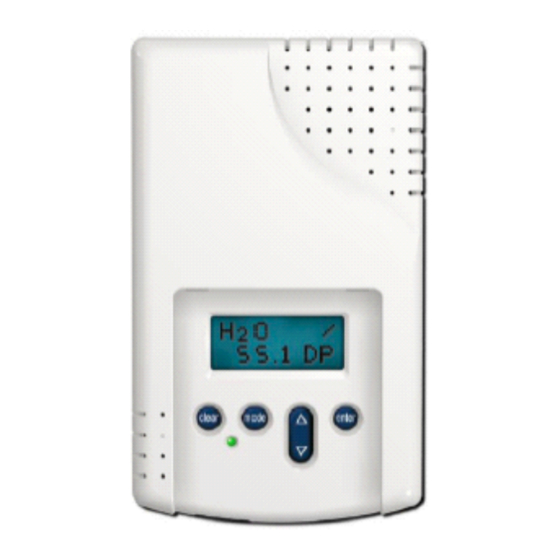
The GE Telaire Vaporstat
9002 sensor
measures in applications in the range of 0
to 80°F dew point. The sensor package is
designed for wall mounting. GE Telaire
offers enclosures for mounting in a variety
of applications including aspirated
sampling of in-duct concentrations,
outside air measurement and measurement
in wet environments.
This manual contains procedures for
installation, wiring and adjustment of the
sensor, and provides conversion
information to translate the dew point measurement of the sensor to
other measurements of humidity, including grains/lb and relative
humidity.
Field Calibration
The sensor features a dual-beam optical assembly that utilizes a neutral
reference measurement to adjust for changes that my occur in the optics.
Although this feature will minimize sensor drift, field calibration at
sensor installation and subsequent periodic calibration is still
recommended to maintain optimum accuracy.
Each sensor has an individually developed curve, based on a certified
chilled mirror hygrometer, with over 8 calibration points. This
individualized curve is stored in the sensor's permanent memory and is
valid for the life of the sensor. Using a reference device to field calibrate
the sensor at a known concentration re-establishes its original calibration
accruacy. Reference devices include a calibrated reference dew point
sensor or GE Telaire's Calibration Kit 2076.
Installing the Sensor
Install the sensor and the mount-
ing plate as follows:
1. Prepare for installation by using
the mounting holes configured
for US or European junction
boxes.
2. Use the mounting plate as a
template to mark the mounting
holes.
3. Secure the mounting plate to the
wall or junction box and make
the necessary wire connections.
4. Mount the Controller on the base
by aligning the top clips and then
securing to the bottom clips. A
"snap" sound will indicate that
the sensor is secure. The sensor
will now have power. A 2 minute
warm-up will take place. After 2 minutes, the sensor will stabilize
and display the "Normal Mode" (current water vapor
concentration).
clear
mode
enter
clear
mode
enter
Infrared Absolute Humidity Sensor
5. Using the procedure outlined in the section "Model 9002 Operating
Modes and Adjustments" , adjust the sensor to provide the proper
elevation correction for your location.
6. Finish installation by sliding the cover over the menu keys and
secure with the screws being provided.
Wiring Diagrams (Typical)
The Model 9002 cannot be wired in a 2-wire configuration where the
power supply also carries the current output of the sensor. Only the 3-
and 4-wire configurations are possible, as shown in Figure 1 below.
Mounting Bracket Pin
Designations
8
7
6
5
4
3
2
1
2
1
Input
Vaporstat
Mounting Bracket
Isolated AC Power 4-Wire
System
18-30 VAC RMS
L2
L1
0-10Vout
Signal Ground
4-20mAout
1
8
7
6
5
4
3
2
2
Input
Vaporstat Mounting Bracket
Figure 1: Wiring Diagrams (3- and 4- Wires)
Telaire Vaporstat™ Model 9002
User Instructions
AC Power 3-Wire System
18-30 VAC RMS
L2
L1
Use Either Output
0-10Vout
4-20mAout
2
1
8
7
6
5
4
3
Input
Common
Vaporstat Mounting Bracket
Using the Relay Contacts
18-30 VAC RMS
L2
L1
1
8
7
6
5
4
3
2
1
Input
NC
COM
Vaporstat
Mounting Bracket
T62873-008
October 2006
Page 1 of 6
2
1
2
1
NO
Advertisement
Table of Contents

Related Manuals for GE Telaire Vaporstat 9002


Summary of Contents for GE Telaire Vaporstat 9002
- Page 1 Using the Relay Contacts the sensor at a known concentration re-establishes its original calibration System accruacy. Reference devices include a calibrated reference dew point 18-30 VAC RMS sensor or GE Telaire’s Calibration Kit 2076. Installing the Sensor 18-30 VAC RMS 0-10Vout Signal Ground...
- Page 2 Model 9002 Operating Modes Factory Settings and Adjustments Table 1: Model 9002 Default Factory Settings Operating Modes Default Measurement Unit Dew Point The Model 9002 has the following three operating modes: Selected Measurement Dew Point Grains/lb Unit Measurement Mode - The sensor operates in the measurement mode. Display °F Dew Point Grains/lb...
- Page 3 Output Adjustments Select the Analog Output Scaling Units It is only necessary to make the adjustments described in this section if The top line of the display will read OUTPUT. you would like to adjust the measurements range of the sensor and/or the analog output range, or adjust relay settings.
- Page 4 Calibration using this technique will re-establish the sensor to its original Determine which calibration procedure you will use to calibrate the factory calibration curve. GE Telaire offers the model 2076 calibration sensor - Single Point or Zero Point calibration. For best results, the kit, which provides a zero calibration gas, certified to have less than 0.1...
- Page 5 Zero Point Calibration Conversion Factors Dew Point and Relative Humidity (RH) All tubing should be connected between the gas bottle and the sensor inlet flow port, as shown in Figure 2 below. Gas should be flowing to the sensor at a rate of 80-100 cc/minute for a minimum of 5 minutes prior to While the measure of relative humidity is highly dependent on the initiating calibration.
- Page 6 DP Range (-3 to 27°C DP) Warranty Repairs (As measured against a factory certified reference): GE Sensing will repair Telaire product that fails to meet the terms ±3.6 °F (2 °C) Dew Point provided for in the Return and Warranty Policy Statement (See, http:// www.gesensing.com/service/brochures.htm).Warranty period shall start...
Need help?
Do you have a question about the Telaire Vaporstat 9002 and is the answer not in the manual?
Questions and answers