
Related Manuals for R9 Technology G200


Summary of Contents for R9 Technology G200
- Page 1 — R9 Technology G200 Gateway Overview This manual provides an overview of R9 Technology’s G200 Gateway. 1 ...
- Page 2 Document Revision Version Date Document Changes Number 4/20/2019 V0.1 Initial Release 2 ...
-
Page 3: Table Of Contents
Table of Contents R9 Technology Device Description ........................4 G200 Cellular Gateway Information ......................4 1.1.1 Powering the G200 Gateway ....................... 5 1.1.2 Gateway Interfaces ..........................5 1.1.3 Gateway Dimensions ........................... 6 1.1.4 Gateway LED Definition ........................7 Picogate Installation ............................8 2.1 Required Items ............................ -
Page 4: R9 Technology Device Description
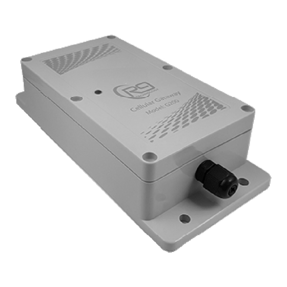
G200 Cellular Gateway Information The G200 cellular gateway provides two local wireless data networks to allow sensor data to flow from sensors, to a web- based server database. The web server database is where sensor data is stored for later retrieval and analysis by the web portal. -
Page 5: Powering The G200 Gateway
The G200 gateway also provides a Lithium Polymer battery-based power backup system. The battery is 3.7V, 2600 mAh, and will allow the G200 to continue to function if the unit is un-plugged, or AC building power is lost. This battery is not serviceable by the end user. -
Page 6: Gateway Dimensions
Power Port – 5V-12V DC power can be input using a DC Jack input. Micro-USB – USB port to use as a generic interface. 5V USB power can also be used to power the G200 (alternative to DC power supply input). -
Page 7: Gateway Led Definition
1.1.4 Gateway LED Definition The gateway product provides one external red/green LED indicator to communicate the status of the gateway to a user. The LED sequences through three modes below with a slight delay (LED out) between stages. After a final long pause, the three modes repeat. -
Page 8: Picogate Installation
Mount the gateway under building eaves, or other protected areas. Install the G200 gateway in an “out of the way” location that is not subject to high levels of foot-traffic by people or animals. -
Page 9: Installation Instructions
Screws Using the base plate of the G200 as a template, mark the two holes for mounting the base plate to the wall. Refer to Figure 1. Ensure the Figure 1 unit is level. ... -
Page 10: Fcc Statement
20cm between the radiator and all persons. This transmitter must not be co-located or operating in conjunction with any other antenna or transmitter. — For questions and support, please contact R9 Technology 17217 Waterview Parkway Suite 1.202Y Dallas, TX, 75252, USA Product information www.r9tech.com...
Need help?
Do you have a question about the G200 and is the answer not in the manual?
Questions and answers